Journal of Electromagnetic Analysis and Applications
Vol. 3 No. 2 (2011) , Article ID: 4125 , 9 pages DOI:10.4236/jemaa.2011.32010
Impact of Islanding on Governor Signal of Distributed Resources
![]()
Neyshabur Branch, Islamic Azad University, Neyshabur, Iran.
Email: mahdi_ghadiri@yahoo.com
Received May 19th, 2010; revised January 8th, 2011; accepted January 26th, 2011
Keywords: Automatic Load Frequency Controller, Distributed Generation, Governor, Islanding Detection, Initial Value Crossing
ABSTRACT
Technical and economical impacts of distributed resources have encouraged big industry managers and distribution systems’ owners to utilize small type of electric generations. One important preventive issue to develop these units is islanding situation. Expert diagnosis system is needed to distinguish network cut off from normal occurrences. It should detect islanding in time to disconnect the unit and prevent any additional failures in equipment. An important part of synchronous generator is automatic load-frequency controller (ALFC). This controller is designed properly to respond to load variations and to fix frequency at constant value when working alone as an islanding system and to control output power when operating in parallel with the main. In this paper, a new approach based on monitoring ALFC response with regard to input signal to governor is introduced. Numbers of initial crossing value are introduced as an index for islanding detection. Simulation results show that input signal to governor has different characteristics in common disturbances.
1. Introduction
Power systems are conventionally designed considering large central power plants to supply various types of loads via transmission and distribution lines. Growing load demand in the power systems will leads to new problems like raising the transmission and distribution lines congestion, transformers overloading, increasing power losses, and declining system reliability. Recently Distributed Generation (DG) units have become more common to conquer these dilemmas. There will be a clear amendment in the distribution system configuration because of Incorporation of DG units at the distribution level. DG sources include many important technical and economic influences via modifying active and reactive power flows. Many Industries and commercial power customers use their own synchronous DGs providing required energy of the industrial units partially. Moreover, these small generators occasionally operate with low power or as stand-by sets. In this situation, they are potentially able to work in parallel with the main and sell energy to local electric company. However, grid operators do not generally dispatch the output powers of the small units working in parallel with the main. Without a suitable operating control system, injection power of DGs besides of increasing fault level and some power quality problems such as harmonics, frequency deviation, and voltage fluctuation can cause most important problem of islanding operation.
According to IEEE STD 1547-2003 [1], an island is a condition where a portion of a grid is energized solely by distributed generators while that portion of the grid is electrically separated from the rest of the power system. After disconnection from the main grid, the islanded system initially faces with power generation mismatch that then will lead to an over generated or under generated situation. Generation less than remained demand leads to low frequency and voltage status in the islanded system; whereas generation over load level can be directed to stabilized frequency and voltage amplitude in the presence of an appropriate voltage and frequency control system. In the early situation, the system voltage and frequency will stay between the predetermined standard limits. Many power systems include reclosers in their structure to protect the equipments against big faults such as lightning and reconnect automatically an isolated part after pre-specified time of operation. Normally a recloser operates and reconnects a tie-line to supply the isolated part again if the fault or any other breaking causes are cleared. Most important issue regarding the DG and reclosers or automatic switches is that embedded generations have not yet been equipped with a reliable recognition facility detecting loss of main after a short while main network islanding. Therefore, reconnections of the networks yield to out of phase reclosing of DGs and failures in the embedded generations. In this situation, large mechanical torques and currents are usually produced that can damage the alternators, prime movers, or other coupled devices. Therefore, the ability to detect islanding situation is a very essential requisite for distributed generators specifically for synchronous generators.
Recently, researchers have done many efforts to develop reliable and economical schemes for islanding detection that can be applied in various distributed systems. The main philosophy of detecting an islanding situation is to monitor and process variations of the output parameters of DG and/or connected system and decides whether islanding has been occurred or not. In general islanding detection techniques can be categorized into remote and local techniques. Local techniques can be further divided into passive, active and hybrid techniques.
Remote islanding detection techniques are based on communications between utilities and DGs. Although these techniques may present reliable performance more than local technique, they are expensive and uneconomical to implement. Transfer trip scheme [2] and Power line signaling scheme [3] contain two major concepts employed in remote islanding detection techniques.
Local detection techniques are based on measurement of the output parameters like voltage, current and frequency at the DG site. Passive methods work on measuring the parameters without any perturbation in connected system. Rate of change of output power [4], rate of change of frequency [5], Harmonic distortion [6], and voltage unbalance [7] are a few common passive techniques.
Active methods are featured to some schemes where inherently disturbances are injected locally into the system and system responses to these disturbances are proceeded to detect islanding conditions. Active schemes include some procedures like reactive power export error detection [8], Slip-Mode Frequency Shift Algorithm (SMS) [9], Active Frequency Drift (AFD) [10], and voltage positive feedback was used in [11].
Hybrid methods have been also developed which use both active and passive detection techniques to detect islanding situation accurately with less influences on the network. Positive feedback (PF), voltage imbalance (VU) [12], adaptive reactive power shift [13], and Average Rate of Voltage Change correlated with Real Power Shift [14] are some examples of the hybrid techniques. As a summary, none of the previously developed methods are perfect. Researchers are being increasingly carried out to discover a reliable and economical method for islanding detection. Islanding is also considered in some papers to study any consequence of islanding situation on system [15].
One of the important parts of a synchronous generator is automatic load-frequency controller (ALFC). These days, all small generators are well equipped with ALFC and governor to keep the frequency of the generator constant. These controllers are designed properly to respond to the load variations and to fix the frequency at constant value when work alone as an islanding system and to control output power when operate in parallel with the main. Therefore, controller behaves differently. In addition, characteristics of internal signals of the controller are not identical for islanding and parallel operating conditions. The authors of this paper think that these signals might be applicable for islanding detection purposes with some confidences. Therefore, in this paper, a new method, based on governor signal monitoring is introduced. Cross Numbers of pre-steady state value is introduced as a discrimination index. Simulation results show that input signal to governor has different characteristics in various load switching and loss of main conditions. No need to any additional devices, no influences on the main system and no further cost are some of the advantages of using governor signal monitoring approach to detect the islanding situation.
2. System and Modeling
The case system in this article study consists of an embedded generator supplying a local load and connected to an infinite bus via a transmission line as shown in Figure 1. Three buses are used to simulate different operating conditions including various islanding situation. The embedded generation unit is a 31.5 KVA small salient pole brushless alternator with a diesel engine prime mover, AVR, and governor.
2.1. Generator
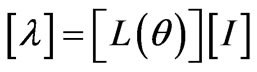
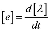
Simulated machine is a three-phase generator which dynamic equations are given in [16]. Linkage flux , the inducted internal voltage,
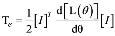
  and electromagnetic torque are defined as fallowing respectively:
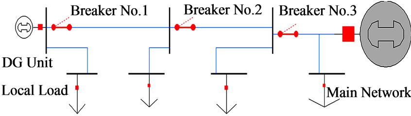
Figure 1. Embedded generation and studied system.
 (1)
(1)
 (2)
(2)
 (3)
(3)
In Equation (1) and Equation (2), the arrays of the inductance matrix comprising the self and mutual inductances of the field and stator windings are defined versus the rotor position angle ( ).
). in Equation (1) and Equation (3) represents current. The parameters of the machine are given in appendix.
2.2. Automatic Voltage Regulator & Excitation System
Figure 2 shows a block diagram of all components of the generator comprising the sampling block, the Automatic Voltage Regulator (AVR), the excitation system and generator. The excitation system itself consists of an inverse design synchronous machine and a full wave three-phase rectifier diode bridge located on the shaft and connected to the armature windings of the exciter machine. The output terminals of the rectifier are connected to the field winding of the main alternator [17,18].
The AVR involves a PID controller that control the duty cycle of output signal (see Figure 3).The output signal of the AVR is used as the input voltage for the field winding of the exciter machine. Parameters values of the AVR are given in appendix.
2.3. Automatic Load Frequency Control System
The main task of the Automatic Load-Frequency Controller (ALFC) system is to maintain both frequency and desired output power of the operation unit simultaneously if possible. Otherwise, it will fix the frequency regardless of the value allocated for the output power set point. This is the case when a generator is isolated from the main network and supplying a local load. However, ALFCs of all existing generation units assist in controlling the frequency and power of a larger interconnection by suitably correction of input torques of turbines to share the load demands. Figure 4 shows a well-known block diagram of ALFC and the parameters are given in appendix.
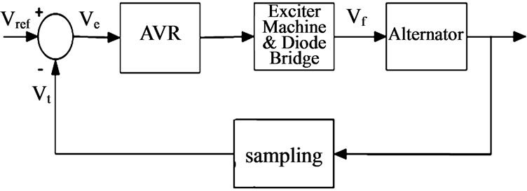
Figure 2. Generator and AVR model.
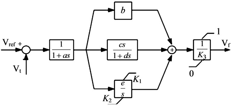
Figure 3. Automatic voltage regulator.
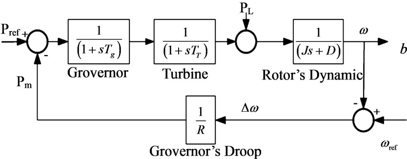
Figure 4. Block diagram of governor, prime mover and rotor dynamics.
3. Proposed Methodology
A power system normally operates in normal state with fully power balance that total generated power is equal to the sum of the demands and losses. In this operating condition, the frequency is a normal pre-specified value. Any disturbances including switching and load variations lead to a short while frequency variations of the system.
When small embedded generation unit is working parallel with an infinite bus via a transmission line, embedded generator always provides its own predetermined power specified by the set point regardless of local load variations. Therefore, the main system affords new load demands. However some speed oscillations occurs nearby the normal speed of the embedded generator when there is a disturbances or load variations. Briefly, dynamic response of the embedded unit is a damped oscillation around the normal frequency.
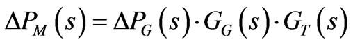
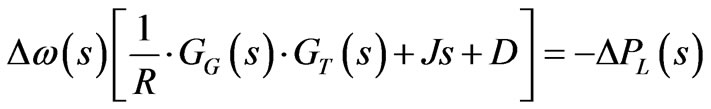
When an embedded generator is suddenly disconnected from the main, it will work separately from the rest of the network serving the local loads. In this situation, ALFC system of the unit attempts to establish the frequency and the generator will supply all remained load in the island system including the local load. However, variation of systems demand will cause a deviation in the frequency depending on the load and ALFC parameters. A loss of main occurrence is somehow similar to a load switching to an isolated generator but of course with some differences. Just for a brief explanation of the islanding system performance, with referring to Figure 4 we have:
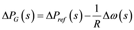 (4)
(4)
Models of the governor and turbine are assumed two simple single pole transfer functions respectively given as:
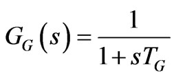 (5)
(5)
 (6)
(6)
Models of the governor and turbine are assumed two simple single pole transfer functions respectively given as:
According to Figure 4, the swing equations can be written as:
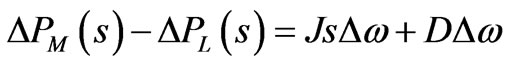 (7)
(7)
 (8)
(8)
 (9)
(9)
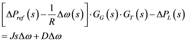
In Equation (9) R is droop of governor. D and J are constants of the rotor of unit.
Substituting Equation (7) into Equation (9) yields to:
 (10)
(10)
If the step-load application is defined as:
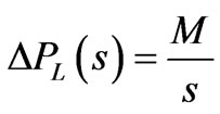 (11)
(11)
Substituting Equations (5), (6), (11) into Equation (10), the speed deviation can be evaluated as:
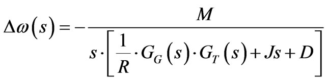 (12)
(12)
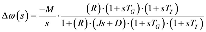 (13)
(13)
Therefore the sustained speed deviation will be:
 (14)
(14)
Dynamic and static responses of an ALFC loop during load applications for an island generator and for the generator working in parallel with the main are not exactly identical. According to Equation (14), a sustained speed and frequency deviation of the island generator depends on the governor parameters and amplitude of the load. Whatever switched load be greater, static frequency error of island system will be more visible. However, in the presence of the main network, load application does not have any influences on the steady state speed of the embedded generator. The speed of the machine is just strictly related to the frequency of the main system, which is assumed to be constant. Moreover, dynamic responses of the ALFC loop and speed oscillations for two different aforementioned operating conditions would be different. These oscillations for embedded generator will be around a constant value specified by the system frequency while for the island system will be around a new value depending on the size and type of the switched load.
The above discussion demonstrates that monitoring of dynamic and static responses of governor may offer an index to discriminate islanding detection from other occurrences such as switching or load applications.
4. Results and Discussions
The system comprising a small 31.5 KVA diesel generator embedded in a distribution network is simulated using MATLAB/SIMULINK environment to study performances of ALFC loop in various operating conditions. The test system as shown in Figure 1, includes a distribution network with three buses and variable loads. The voltage sources shown in Figure 1 indicate the infinite bus.
All parameter and amplitudes are normalized via proper base, as mentioned in the appendix to facilitate in simulation and comparing results the performance of input signal to the governor. According to the IEEE STD 1547-2003, maximum allowed time to detect islanding situation is 2 seconds. So, all figures of input signals to the governor have been illustrated within 2 seconds. The nominal rate of DG power has been tuned on 0.2 p.u.
4.1. Load Switching in Presence of Main System
One of the most common disturbances in power system is load variation. During a day, load profile consist so much variation. Behavior of Input signal to the governor is highly depended on both switched load size and place .In this scenario various loads are connected and disconnected then from the studied system.
4.1.1. Load Switching between Breaker No. 1 and Breaker No. 2
Switching loads to the network causes to Oscillation in input signal to the governor. The main network and DG unit seek to share the load variation with respect to network structure, variation amount, and DG capacity. The ALFC system tries to balance itself with new circumstance. Because of regulation value of ALFC, any oscillation will be damped in few seconds. In the case of load switching, variation of the input signal to governor would be more explicit as load variation being more considerable. This behavior is shown in Figures 5 and 6.
4.1.2. Load Switching between Breaker No. 2 and Breaker No. 3
In this section, a scenario is considered to study the effect of load switching far away from the unit. Similar to the previous section, four amounts of loads are switched on and then disconnected. Dynamic performance of the governor in this scenario has been illustrated in Figures 7 and 8.
The clear distinction between Figures 8 and 9 with Figures 6 and 7 is the performance of input signal to the governor with regard to switched load amounts. The Dynamic responses of various types of loads have negligible
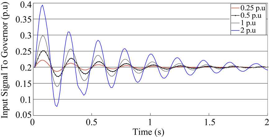
Figure 5. Input signal to the governor with regard to section 5.1.1.
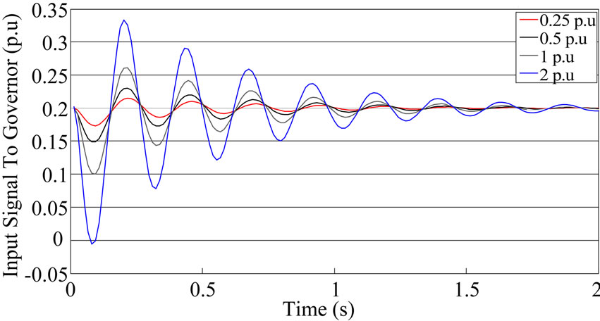
Figure 6. Input signal to the governor with regard to section 5.1.1.
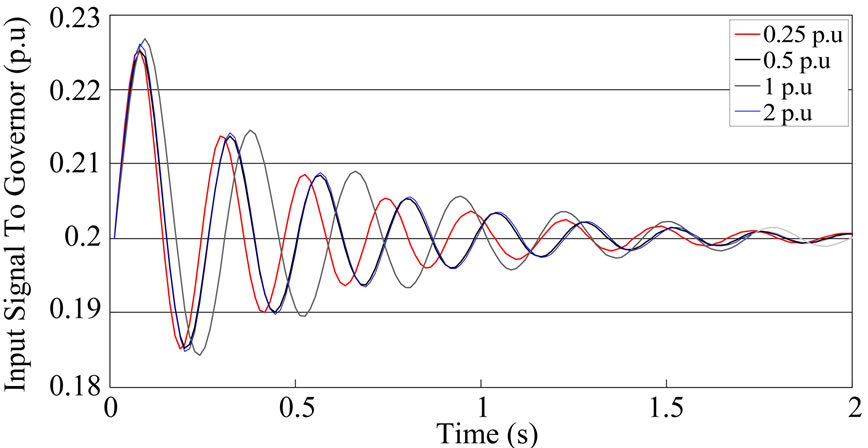
Figure 7. Input signal to the governor regard to section 5.1.2.
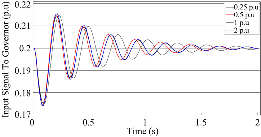
Figure 8. Input signal to the governor regard to section 5.1.2.
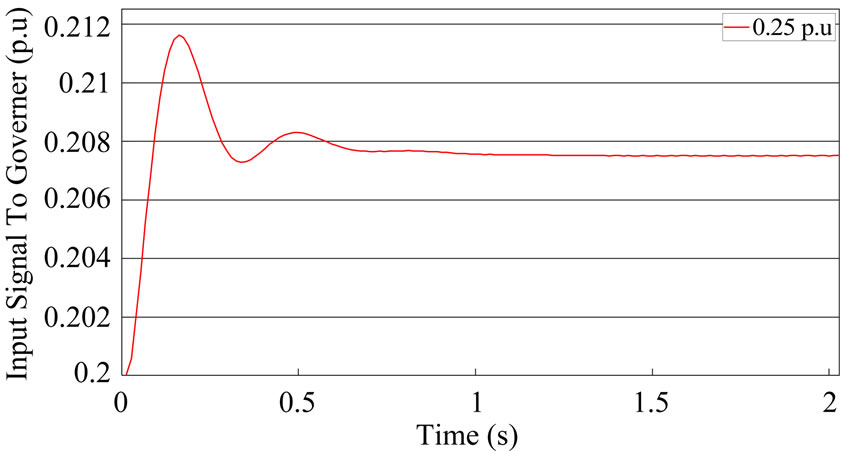
Figure 9. Input signal to the governor regard to section 5.2.1.
difference in the case of load variation far from DG site. Deviations of signals have been also decreased totally.
4.2. Islanding Situation
According to the Figure 6, breakers operating may lead to islanding situation. Therefore, parallel working of DG with network turns into isolated system containing DG unit as main supply. One of the major failing points of various techniques is equality of the supplied load of embedded Generation before and after islanding situation. Conventional procedures are usually unable to detect this situation. In this scenario, it has been initially supposed that local load is equal to the rate of embedded generation. This assumption helps to study dynamic performance of input signal to governor, when the power of DG is identical.
When the distributed generator becomes disconnected from the main supply, it would tries to supply the demand of the new island solely. Therefore, input signal to the governor would be modified to keep speed of DG rotor constant.
4.2.1. Islanding Situation Caused by Breaker No. 1
Some scenarios are designed to simulate the power island that just involves DG site and its local load. Input signal to the governor modifies to adjust unit with new situation (see Equation (14)) in absence of main network. Dynamic response of input signal to the governor has been depicted in Figure 9.
4.2.2. Islanding Situation Caused by Breaker No. 2
Intentional or natural Operation of breakers No. 2 or No. 3 in Figure 1, forms an island consisting DG site and some loads from the rest of the network. In this situation, frequency of the island will drop because of inability of DG to supply remained demand. A scenario including 3 amounts of loads are simulated in this section.
To guarantee frequency stability of island, light and normal amounts of loads are switched on DG site (Figure 10). One of the simulation stages are based on equality of DG generation and island demand. This assumption helps to understand the dynamic response and oscillating behavior of mentioned signal similar to section 4.2.1 (Figure 11).
4.2.3. Islanding Situation Caused by Breaker No. 3
Similarly, an islanding situation by breaker No. 3 is simulated (see Figure 12).
4.3. Capacitor Bank Switching
Power systems usually use capacitor banks for various purposes. Utilization of capacitor banks makes many advantages like locally reactive power compensation, improvement of voltage profile, and market power reduction. Nonetheless, switching of the capacitors causes disturbance to involved system.
To realize difference between islanding situation and capacitor bank switching, a scenario containing capacitor switching, has been simulated in several places of test system (Figures 13-15).Totally, Capacitor switching imposes transient oscillation to input signal to governor as well as small perturbations exactly after the switching.
4.4. Three-Phase Fault
Fault in transmission lines commonly take places with different reasons. This issue put emphasize on fault simulation especially in power systems comprising DG units.
In this scenario, three-phase fault are simulated with different amounts of fault impedances. Fault duration
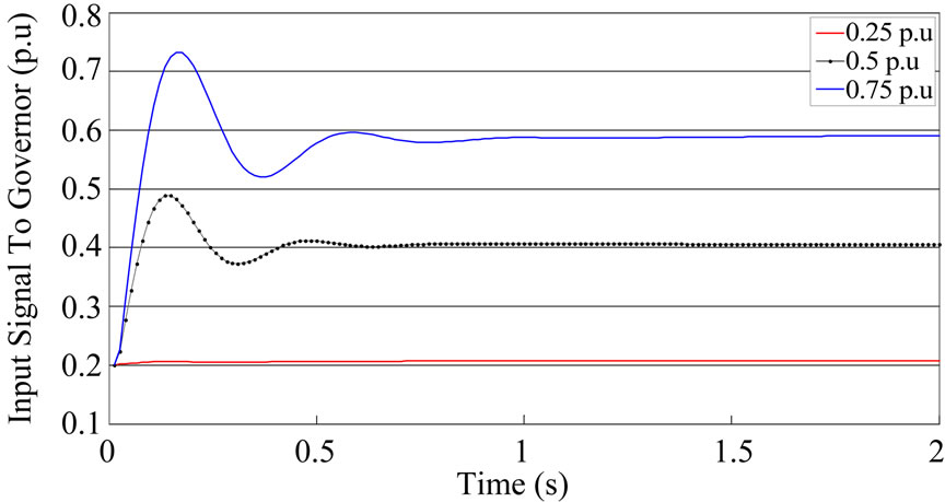
Figure 10. Input signal to the governor regard to section 5.2.2.
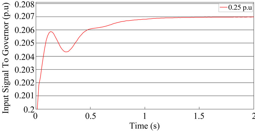
Figure 11. Input signal to the governor regard to section 5.2.2.
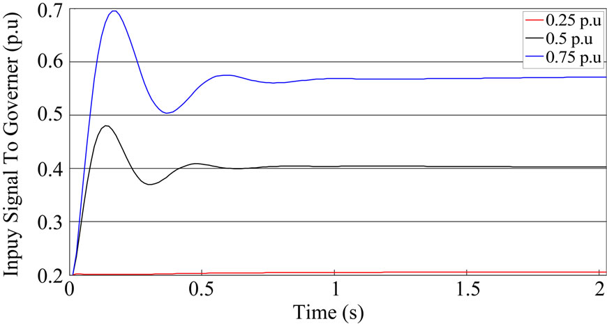
Figure 12. Input signal to the governor regard to section 5.2.3.
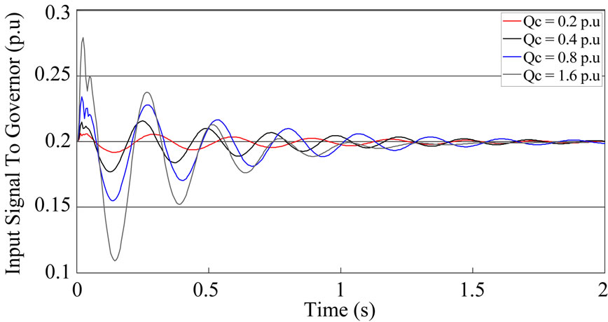
Figure 13. Input signal to the governor through capacitor switching close to the DG.
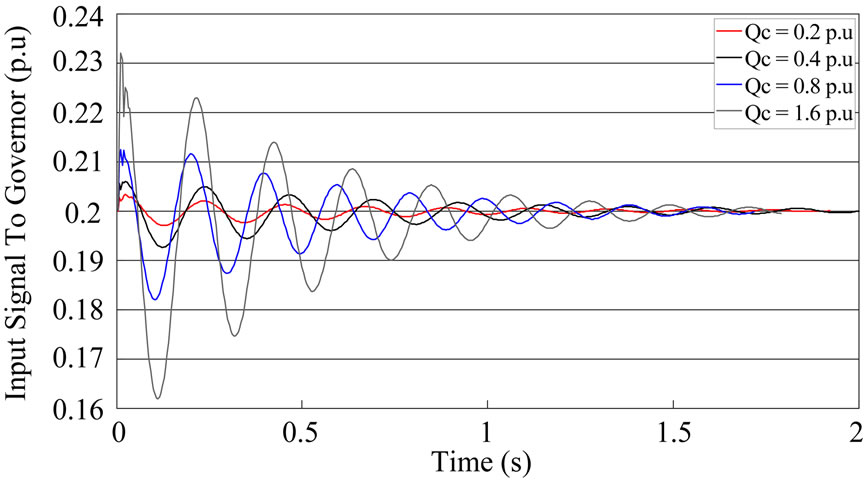
Figure 14. Input signal to the governor through capacitor switching between breaker No. 1 and No. 2.
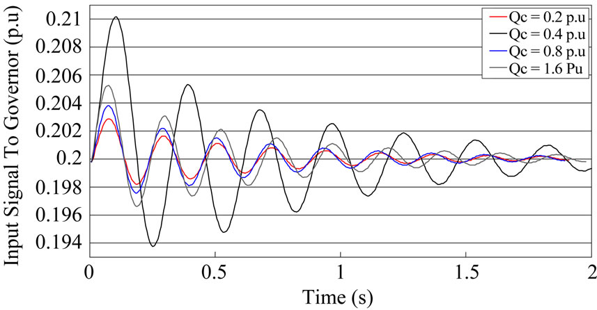
Figure 15. Input signal to the governor through capacitor switching between breaker No. 2 and No. 3.
time has been set 2 cycles. Similar to the previous scenarios, faults are simulated in various places of test system. Simulations results have been illustrated in figures 16, 17 and 18.
Considering various designed scenarios, a significant difference of ALFC in Islanding situation is the oscillation circumstance of input signal to the governor. Load switching phenomena lead to oscillations around the primary set point of the mechanical torque. These oscillations damp within about 1.5 seconds after switch operation. Capacitor switching includes small transient oscillations exactly after the capacitor switch operation. These transient oscillations damp through the first cycle of main oscillation. In the case of fault, there are more oscillations within the two seconds with respect to the other phenomena. These behaviors show a network comprising main and embedded generation needs more times to overcome caused oscillations by fault occurrence. Less alternation, non-crossing initial value, static error, and high primary acceleration are some the features of the input signal to governor in islanding situation. These differences between islanding situation and other similar phenomena could be useful to define a new discrimination index based on the input signal to the governor.
Initial value crossing can be a proper discrimination index to distinguish islanding and non-islanding phenomena. Initial value crossing is defined as passage number of pre-steady state of input signal. As Shown in Figures 5-8 and Figures 13-18, Load variation, capacitor switching, and fault effects have damping sinusoidal oscillation. A while after occurrence, input signal of governor of DG would diminish exactly in previous steady state value. On other hand, input signal to governor related to islanding situation does not pass initial value as well as other occurrences. Depend on islanded load, input signal to governor damps to over, under or pre-steady state value. In non-islanding situation, there are about 4 up to 6 initial value crossing within 500 ms (see Figures 5-8 and Figures 13-18). However, input signal of governor in islanding situation pass through initial value 1 time (see Figures 9-12). All above are resulted because main network controls frequency when embedded unit is connected to network; whereas embedded unit controls remained load when there is an islanding situation.
5. Conclusion
One of the important parts of a synchronous generator is automatic load-frequency controller (ALFC). This controller is designed properly to respond to load variations and to fix the frequency at constant value when working alone as an islanding system and to control output power when operating in parallel with the main. In this paper, dynamic responses of the input signal to the governor
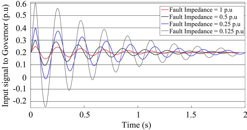
Figure 16. Input signal to the governor through three phase fault close to the DG unit.
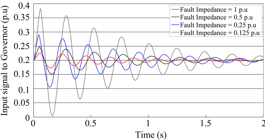
Figure 17. Input signal to the governor through three phase fault between breaker No. 1 and No. 2.
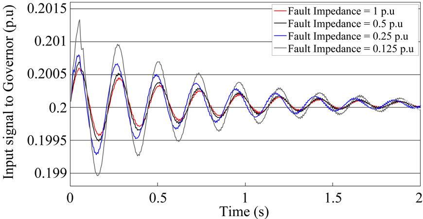
Figure 18. Input signal to the governor through three phase fault between breaker No. 2 and No. 3.
have been simulated in various scenarios. Simulation results show that the input signal to the governor has different characteristics in various disturbances and loss of main conditions. No need to any additional devices, no influences on the main system and no further cost are some of the advantages of using governor signal monitoring approach to detect the islanding situation.
REFERENCES
- IEEE Standard for Interconnecting Distributed Sources with Electric Power Systems, IEEE Standard 1547, 2003.
- M. A. Refern, O. Usta and G. Fielding, “Protection against Loss of Utility Grid Supply for a Dispersed Storage and Generation Unit,” IEEE Transaction on Power Delivery, vol. 8, no. 3, July 1993, pp. 948-954. doi:10.1109/61.252622
- M. Ropp, K. Aaker, J. Haigh and N. Sabhah, “Using Power Line Carrier Communications to Prevent Islanding,” Proceedings of 28th IEEE Photovoltaic Specialist Conference, 2000, pp. 1675-1678.
- M. A. Redfern, J. I. Barren and O. Usta, “A New Microprocessor Based Islanding Protection Algorithm for Dispersed Storage and Generation Units,” IEEE Transactions on Power Delivery, vol. 10, no. 3, July 1995, pp. 1249- 1254. doi:10.1109/61.400903
- J. Warin and W. H. Allen, “Loss of Mains Protection,” Proceedings of 1990 ERA Conference on Circuit Protection for industrial and Commercial Installation, London, pp. 1-12.
- S. Jang and K. Kim, “Development of a Logical RuleBased Islanding Detection Method for Distributed Resources,” Proceedings of IEEE Power Engineering Society Winter Meeting, vol. 2, 2002, pp. 800-806.
- S. I. Jang and K. H. Kim, “An Islanding Detection Method for Distributed Generations Using Voltage Unbalance and Total Harmonic Distortion of Current,” IEEE Transactions on Power Delivery, vol. 19, no. 2, April 2004, pp. 745-752. doi:10.1109/TPWRD.2003.822964
- P. D. Hopewell, N. Jenkins and A. D. Cross, “Loss of Mains Detection for Small Generators,” IEE Proceedings of Electric Power Applications, vol. 143, no. 3, May 1996, pp. 225-230. doi:10.1049/ip-epa:19960286
- G. A. Smith, P. A. Onions and D. G. Infield, “Predicting Islanding Operation of Grid Connected PV Inverters,” IEE Proceedings of Electric Power Applications, vol. 147, January 2000, pp. 1-6. doi:10.1049/ip-epa:20000004
- M. E. Ropp, M. Begovic and A. Rohatgi, “Analysis and Performance Assessment of the Active Frequency Drift Method of Islanding Prevention,” IEEE Transactions on Energy Conversion, vol. 14, no 3, September 1999, pp. 810-816. doi:10.1109/60.790956
- A. Cardenas, K. Agbossou and M. L. Doumbia, “Islanding Detection Method for Multi-Inverter Distributed Generation,” Journal of Electromagnetic Analysis & Applications, September 2009.
- V. Menon and M. H. Nehrir, “A Hybrid Islanding Detection Technique Using Voltage Unbalance and Frequency Set Point,” IEEE Transactions on Power Systems, vol. 22, no. 1, Feburary 2007, pp. 442-448. doi:10.1109/TPWRS.2006.887892
- J. Yin, L. Chang and C. Diduch, “A New Hybrid AntiIslanding Algorithm in Grid Connected Three-Phase Inverter System,” 2006 IEEE Power Electronics Specialists Conference, pp. 1-7.
- P. Mahat, Z. Chen and B. Bak-Jensen, “A Hybrid Islanding Detection Technique Using Average Rate of Voltage Change and Real Power Shift”, IEEE Transactions on Power Delivery, Vol. 24, No. 2, April 2009.
- A. Ranjan, S. P. Karthikeyan, A. Ahuja, K. Palanisamy, I. J. Raglend and D. P. Kothari, “Impact of Reactive Power in Power Evacuation from Wind Turbines,” Journal of Electromagnetic Analysis & Applications, Vol. 1, 2009, pp. 15-23.
- A. Darabi, “Auxiliary Windings, Supplying the AVR of a Brushless Synchronous Generator,” Eighth International Conference on Electrical Machines and Systems (ICEMS), Vol. 1, September 2005, pp. 81-85.
- A. Darabi and C. E. Tindall, “Analogue AVR Model for Use in Real Time Transient Simulation of Small Salient Pole Alternators,” IEEE Conference Publication, Power Electronics, Machines and Drives, No. 487, April 2002, pp. 451-455. doi:10.1049/cp:20020159
- A. Darabi, C. Tindall and S. Ferguson, “Finite-Element Time-Step Coupled Generator, Load, AVR, and Brushless Exciter Modeling,” IEEE Transactions on Energy Conversion, Vol. 19, No. 2, June 2004, pp. 258-264.
Appendix
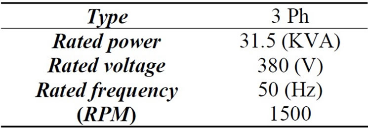
Table 1. Individual Generator Rating.
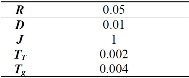
Table 2. Governor DATA (p.u).
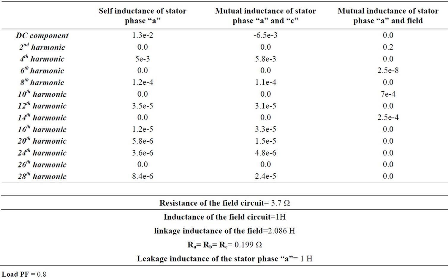
Table 3. Parameters of the synchronous machine.
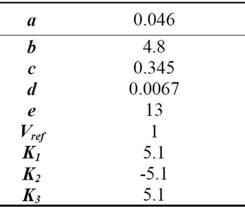
Table 4. AVR DATA (p.u).