Journal of Electromagnetic Analysis and Applications
Vol. 2 No. 4 (2010) , Article ID: 1679 , 6 pages DOI:10.4236/jemaa.2010.24032
Developing a 3D-FEM Model for Electromagnetic Analysis of an Axial Flux Permanent Magnet Machine
![]()
Department of Electrical Engineering, Centre of Excellence for Power Systems Automation and Operation, Iran University of Science & Technology, Tehran, Iran.
Email: mehdimirimani@gmail.com, avahedi@iust.ac.ir
Received December 13th, 2009; revised January 27th, 2010; accepted February 4th, 2010.
Keywords: Axial Flux Permanent Magnet (AFPM) Motor, Three-Dimensional Finite-Element Method (3D-FEM), Cogging Torque
ABSTRACT
Recently, many optimal designs for axial flux permanent magnet (AFPM) motors were performed based on finiteelement (FE) analysis. Most of the models are based on reduction of 3D problem to 2D problem which is not accurate for design aspects. This paper describes an accurate electromagnetic analysis of a surface mounted, 28 pole AFPM with concentrated stator winding. The AFPM is modeled with three-dimensional finite-element method. This model includes all geometrical and physical characteristics of the machine components. Using this accurate modeling makes it possible to obtain demanded signals for a very high precision analysis. Magnetic flux density, back-EMF, magnetic axial force and cogging torque of the motor are simulated using FLUX-3D V10.3.2. Meanwhile, the model is parametric and can be used for design process and sensitivity analysis.
1. Introduction
Axial Flux Permanent Magnet Machines (AFPMM) firstly appeared in technical literatures in the mid of 70s and their fields of application spread widely. AFPM machines are increasingly used in various applications due to their high efficiency, compact construction and high torque at low speed [1-3]. AFPM unique topologies allow designers to design multi pole machines. Thus, it can be directly coupled to the lowspeed turbines, such as wind and hydro turbines [4]. Their robustness and compactness make high-speed axial-flux machines suitable for distributed generating application [5]. It is also a suitable candidate for electric vehicle (EV) and traction motors [6].
Modeling of electrical machines is very important because of its usage in study of machines behavior and optimization process. Modeling methods of electrical machines can be categorized into analytical modeling and numerical modeling. Analytical modeling has the profit of rapidity but, the accuracy of this modeling is not enough for optimization in design process. Instead, Numerical modeling is very accurate method but this method is time consuming. Numerical modeling is used in applications Such as design and optimization of electrical devices that accurate modeling is needed. In such applications, accuracy is very important and duration of simulation has less importance. Numerical method is based on discretization of calculation domain to finite elements and solving Maxwell equations in these elements. Finite-element method can be categorized into two-dimensional (2D) and three-dimensional (3D) method. 3D form is more time consuming but it has higher accuracy than 2D modeling. Many literates have demonstrated that AFPM Machines are intrinsically 3-D machines and accurately analyzing the behavior of these machines needs 3D-FEM modeling [7]. Many of the literatures model an AFPM based on reduction of the 3D problem to a 2D problem. These models are not accurate for design process and sensitivity analysis [1,8,9].
In this paper, a surface mounted axial flux permanent magnet (AFPM) motor with concentrated coils is modeled using 3-dimensional finite element method. Magnetic flux density of airgap, back-EMF, axial forces between rotor and stator and cogging torque are calculated.
This accurate model can be used for design process and sensitivity analysis.
2. Motor Specification
Figure 1 shows a three-phase, 210-V, 2200-W, 1285- rpm, ∆-connected AFPM machine that was modeled. It consists of a stator with 24 slots and 12 single layer concentrated coils with fractional winding. Fractional slot windings allow a large number of poles to be designed without increasing the number of slots by putting less than one slot per phase under each rotor pole. This procedure results also into a more compact winding design, allowing for less copper losses due to shorter end connections. The concentrated winding allows a large number of pole pairs to be designed even in a small machine [10]. Coils with a same color in the model belong to one phase. The rotor disc consists of 28 magnets of alternating polarity. The machine parameters are given in Table 1 [7].
3. Finite Element Simulation
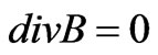
Many literates have demonstrated that accurate analysis of AFPM behaviors is not an easy task because these types of machines are intrinsically 3-D machines [7,8]. Three dimensional finite-element method (FEM) allows a precise analysis of magnetic devices taking into account geometric details and magnetic nonlinearity. So, it is an appropriate method for analyzing AFPMs. By using this accurate modeling it is possible to obtain demanded signals for a very high precision analysis. Finite element method is based on Maxwell’s equations. The electro-
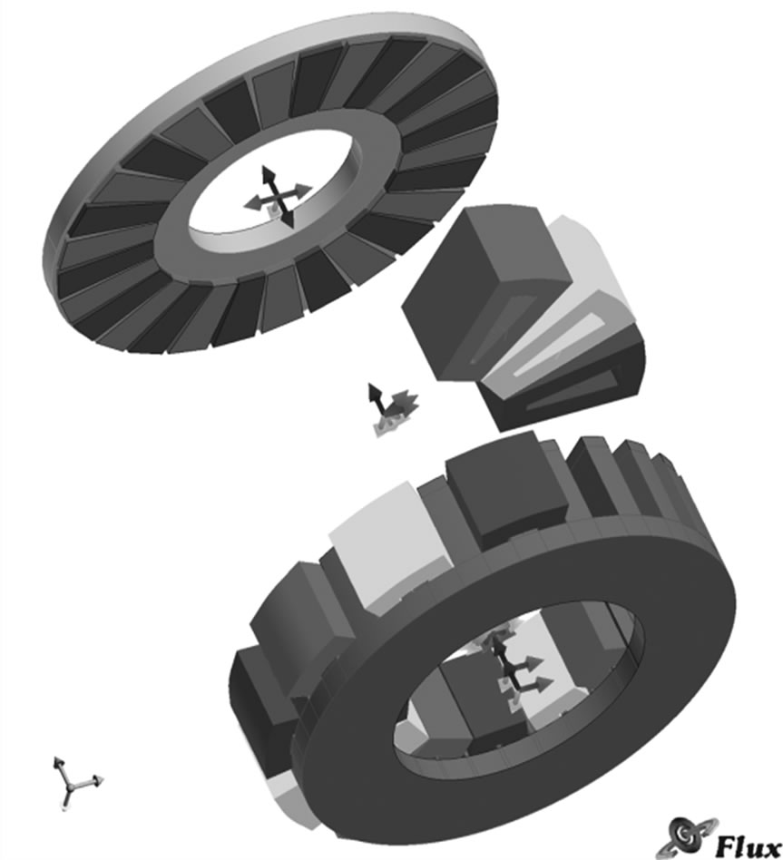
Figure 1. Twenty-eight pole three-phase AFPM
magnetic field of the machine is given by:
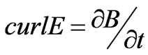
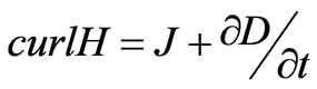 (1)
(1)
The center of the stator is fixed at the origin of the global coordinate system. The center of the rotor is located at the origin of the local coordinate system, which rotate around the center of the global coordinate system, i.e. the center of the stator, by a constant step angle. Investigation of AFPM model was made with the assumptions of nonlinear materials. In order to have high level of precision, the mesh diagram is designed manually. Figure 2 shows mesh diagram of the proposed motor and as it shows, density of meshes increases near the air-gap in order to a precise simulation. Whole nodes number is 460,000 in this simulation. This amount of nodes is very high and will warrant the accuracy of simulation. Figure 3 demonstrates the flux diagram of motor. It shows that maximum flux density in hotspots is 2.147 T. Three-dimensional finite-element analysis (3D-FEA) software FLUX2D/3D by CEDRAT is used to simulate the motor [9]. Figure 2 shows The FEM model that was used in this paper.
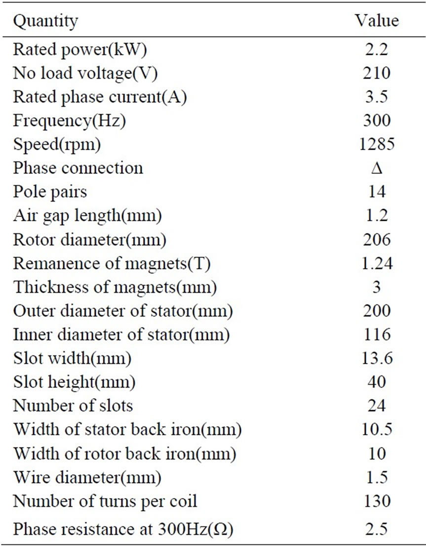
Table 1. Specifications of the motor
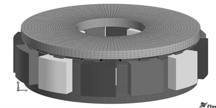
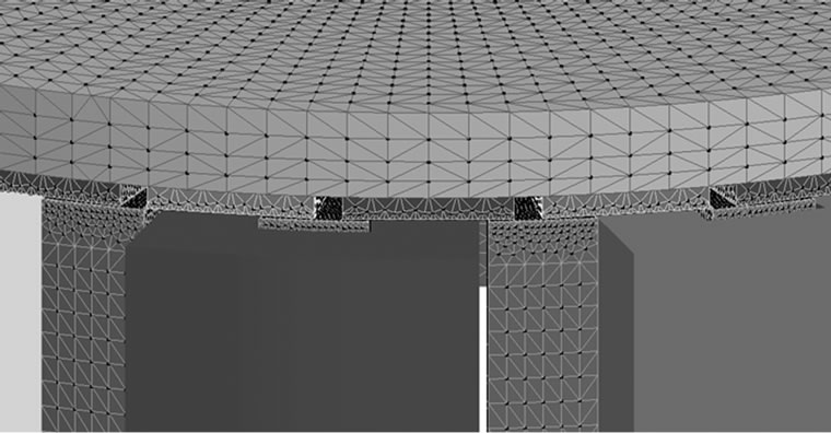
Figure 2. Three-dimensional mesh model
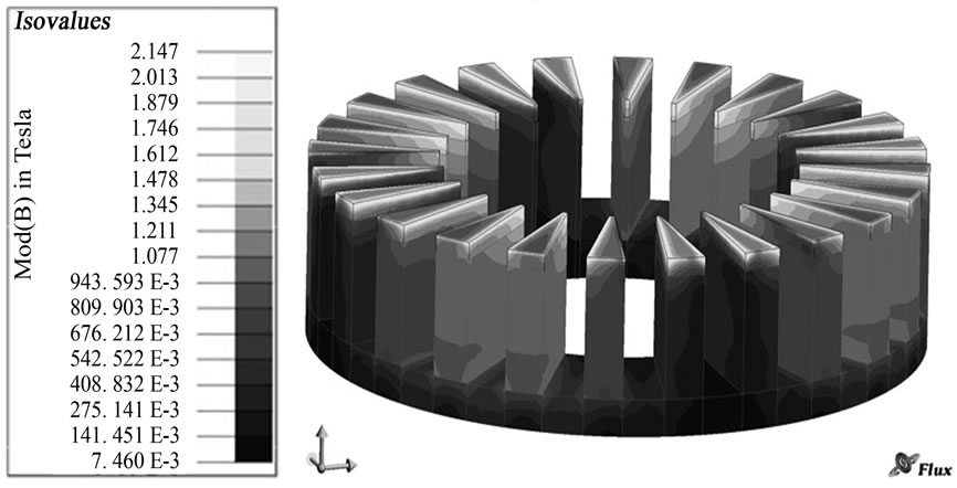
Figure 3. Flux density distribution in the stator
3.1. Calculation of Airgap Flux Density
One of the most important characteristics of the motor is airgap flux density. So, it was simulated under no-load condition to monitor the airgap pattern. Figure 4 shows the axial component of the no-load air-gap flux density due to permanent magnets in the middle of airgap plane. Moreover, the z-component of the no-load air-gap flux density was computed over a circumference in the plane. Figure 5 reports the waveform.
3.2. Axial Force between Rotor and Stator
In axial flux permanent magnet machines, there is an axial force between rotor magnets and stator teeth. Figure 6 represents the schematic of this axial force. Figure 7 shows that the period of this force fluctuation is equal to the angular distance between two identical permanent magnets. It means that after this angular displacement, a N pole replaces by another coming one and the situation of permanent magnets toward the stator teeth becomes similar to the previous position. The force fluctuations will repeat a same manner in other periods. The period is obtained as follows:
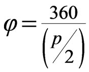 (2)
(2)
where p is number of machine poles. Figure 8 shows the total magnetic force fluctuates of the motor in one period. This trend will repeat in other periods. Its mean value is 2152 N. Figure 9 shows frequency spectrum of the axial force.
3.3. Calculation of Back-EMF
In this case, the back EMF is sinusoidal due to the windings layout. Figure 10 shows the Back-EMF of the motor at no-load and its RMS value is 209.996 V. The
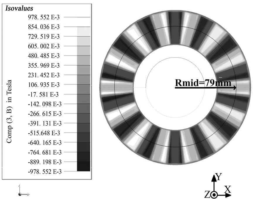
Figure 4. Axial component of the no-load air-gap flux density
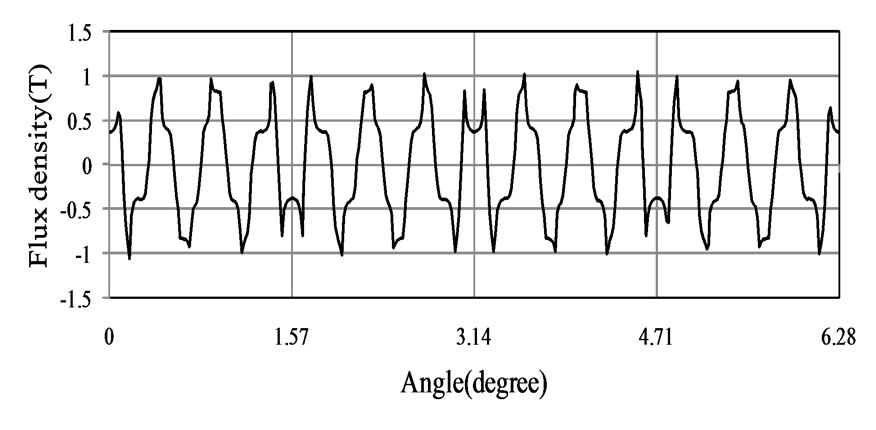
Figure 5. Z-component of the no-load air-gap flux density over a circumference in the middle of air-gap plane (r = 79 mm)
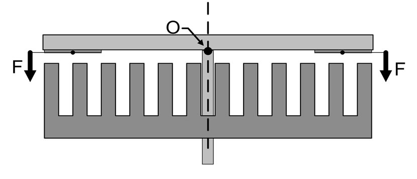
Figure 6. Schematic representation of axial forces in axial flux permanent magnet motor
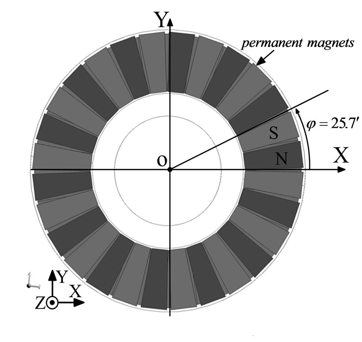
Figure 7. Top view of permanent magnets
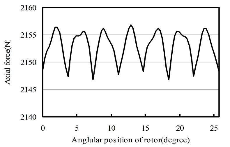
Figure 8. Axial force between rotor and stator
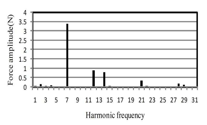
Figure 9. Frequency spectrum of the Axial force between rotor and stator
nominal voltage of motor is 210 V and it can be seen that the simulated voltage has a good agreement with the nominal one. Figure 11 illustrates frequency spectrum of the back-EMF. It shows that the superior harmonics in the spectrum is the first harmonic with amplitude of 289.08 V and then the fifth harmonic with amplitude of 3.02 V. Existence of harmonics is dependent on nonlinearity of core and concentration of coils.
From the amplitude of back-EMF, the permanent magnet fundamental flux is calculated:
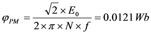 (3)
(3)
N is the number of turns per coil, E0 is the RMS value of back-EMF and f is the frequency.
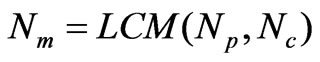
3.3. Calculation of Cogging Torque
The vibration and acoustic noise of machines is a very important factor. The research for vibration of PM machines which is a kind of new efficient machines is more and more attended. High torque density and efficiency of axial flux permanent magnet machines make them an ideal choice in many high performance applications. However, cogging torque in these machines has undesirable effects of torque ripple, noise and vibration. This torque is proportional to the PM flux and the reluctance variation, and is independent of the load current. In PM machines, cogging torque arises from the magnet’s tendency to align itself with the minimum reluctance path given by the relative position between rotor and stator. This is an inherent characteristic of AFPMs. It was calculated and shown in Figure 12. A closer inspection of
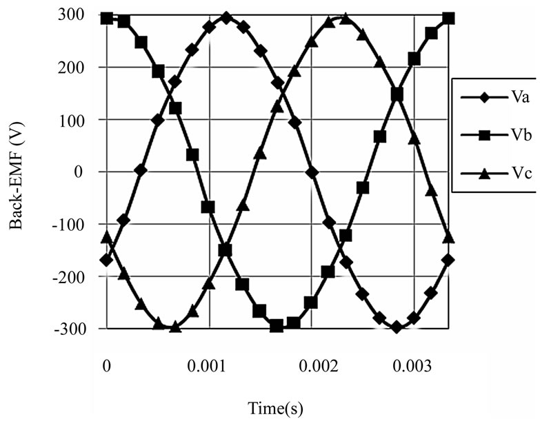
Figure 10. Back-EMF of the motor
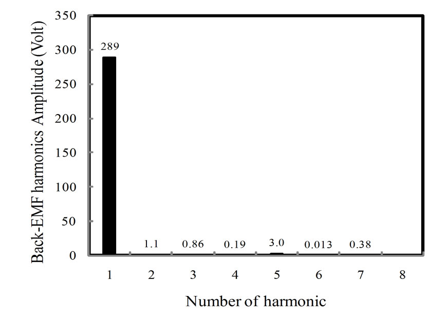
Figure 11. Frequency spectrum of the Back-EMF
Figure 12 shows a low frequency modulation of the torque ripple. As cogging torque is minimized through successful optimization, the relative proportion of the low-frequency component increases and becomes noticeable. However, for machines with very low amount of cogging torque, the low frequency component can add a noticeable ratio of ripple to overall cogging amplitude [11]. The number of periods of the cogging torque per rotor revolution is:
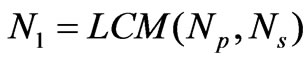 (4)
(4)
where Ns is the number of slots and Np is the number of poles. Nl = 168 is the least common multiple of Ns = 24 and Np = 28. It means that the cogging torque period is 2.14 degrees. In Figure 12, 14 cycles occur over an angular displacement of about 30 degree, yielding the requisite 168 cycles in 2п radians. The modulation harmonic was discussed in [11]. By definition:
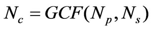 (5)
(5)
 (6)
(6)
Nm is the number of periods of the modulation frequency per rotor revolution. Nm = 28 and it means that we have 28 periods of modulation frequency in 2п radians. So, the modulation harmonic period is 12.857 degree that is six times of the period of main harmonic.
Figure 13 shows the harmonics of cogging torque com-
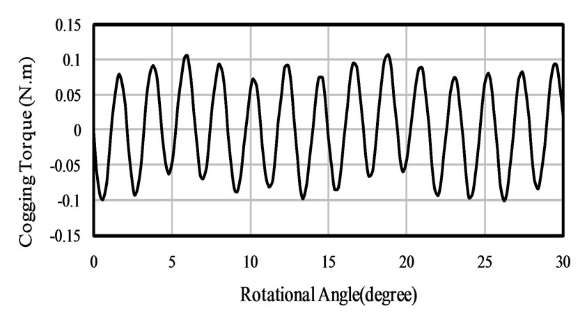
Figure 12. Cogging torque waveform of the motor
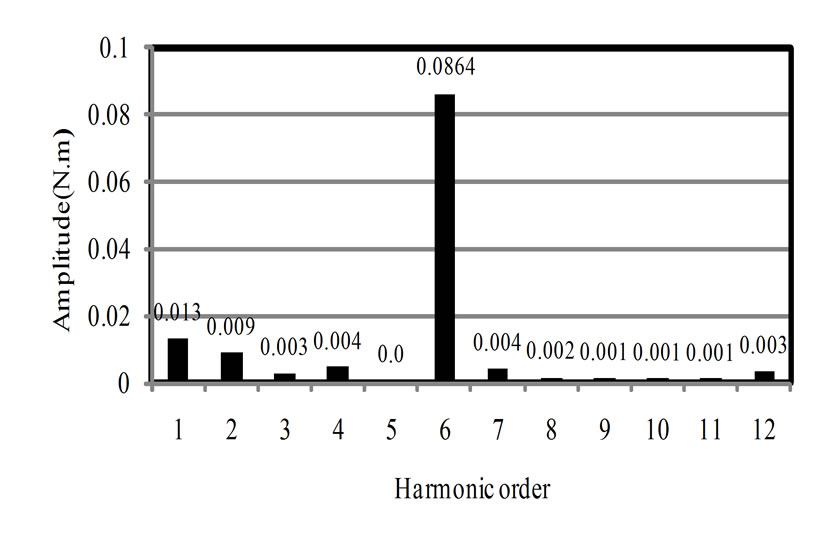
Figure 13. Frequency spectrum of the cogging torque
puted via three-dimensional FEM analysis. It shows that there are two superior harmonics in the spectrum. First harmonic belongs to modulation frequency and sixth belongs to the main frequency of cogging torque that repeats 6 times in the period of modulation frequency.
5. Conclusions
The paper addresses electromagnetic characteristics of an axial flux permanent magnet machine. A threedimensional finite element analysis model is presented for accurate analysis of the Axial Flux Permanent Magnet motor. This model is parametric one and can be used for design process and sensitivity analysis of AFPM machine. Air-gap flux density, back-EMF, axial forces and cogging torque was calculated using this model and it is shown that the simulation results have a good agreement with the motor’s characteristics and nominal values.
6. Acknowledgments
The authors would like to thank Dr. Fabrizio Marignetti of University of Cassino (Italy) for his helps and advices.
REFERENCES
- N. Chaker, I. B. Salah, S. Tounsi and R. Neji, “Design of Axial-Flux Motor for Traction Application,” Journal of Electromagnetic Analysis and Applications, Vol. 1, No. 2, June 2009, pp. 73-83.
- F. Caricchi, F. Crescimbini, F. Mezzetti and E. Santini, “Multistage Axial Flux PM Machine for Wheel Direct Drive,” IEEE Transactions on Industry Applications, Vol. 32, No. 4, 1996, pp. 882-887.
- A. B. Letelier, D. A. González, J. A. Tapia, R. Wallace and M. A. Valenzuela, “Cogging Torque Reduction in an Axial Flux PM Machine via Stator Slot Displacement and Skewing,” IEEE Transactions on Industrial Applications, Vol. 43, No. 3, May 2007, pp. 685-693.
- Y. Chen, P. Pillay and A. Khan. “PM Wind Generator Comparison of Different Topologies,” Conference Record of IEEE 39th Inustrial Applications Annual Meeting, Vol. 3, October 2004, pp. 1405-1412.
- S. M. Hosseini, M. Agha-Mirsalim, and M. Mirzaei, “Design, Prototyping and Analysis of Low Cost Axial-Flux Coreless Permanent-Magnet Generator,” IEEE Transactions on Magnetics, Vol. 44, 2008, pp. 75-80.
- Y.-P. Yang and D. S. Chuang, “Optimal Design and Control of a Wheel Motor for Electric Passenger Cars,” IEEE Transactions on Magetics, Vol. 43, 2007, 51-61.
- F. Marignetti, V. Delli Colli and Y. Coia, “Design of Axial Flux PM Synchronous Machines Through 3-D Coupled Electromagnetic Thermal and Fluid-Dynamical FiniteElement Analysis,” IEEE Transactions on Industrial Electronics, Vol. 55, No. 10, October 2008, pp. 3591-3601.
- P. R. Upadhyay and K. R. Rajagopal, “FE Analysis and Computer-Aided Design of a Sandwiched Axial-Flux Permanent Magnet Brushless DC Motor,” IEEE Transaction on Magnetics, Vol. 42, No. 10, October 2006, pp. 3401-3403.
- Y.-P. Yang, J.-P. Wang, S.-W. Wu and Y.-P. Luh, “Design and Control of Axial-Flux Brushless DC Wheel Motors for Electric Vehicles—Part II: Optimal Current Waveforms and Performance Test,” IEEE Transaction on Magnetics, Vol. 40, No. 4, July 2004, pp. 1883-1891.
- F. Marignetti, G. Tomassi, P. Cancelliere, V. Delli Colli, R. D. Stefano and M. Scarano. “Electromagnetic and Mechanical Design of a Fractional-slot-windings Axialflux PM Synchronous Machine with Soft Magnetic Compound Stator,” IEEE Industry Applications Conference, 2006, pp. 62-69.
- D. R. McIntosh, “Identification and Analysis of LowFrequency Cogging Torque Component in Permanent Magnet Machines,” Proceedings of the COMSOL Conference, Boston, 1 January 2008.