Journal of Electromagnetic Analysis and Applications
Vol. 1 No. 1 (2009) , Article ID: 192 , 7 pages DOI:10.4236/jemaa.2009.11005
Some Advances in the Application of Weathering and Cold-Formed Steel in Transmission Tower
1China Electric Power Research Institute, Beijing, China
Email: yangfl1@epri.ac.cn, flyangbj@tom.com
Received January 12th, 2009; revised February 4th, 2009; accepted February 16th, 2009.
Keywords: Weathering Steel, Cold-Formed Steel, Bolted Joint, Corrosion-Resistant Test, Prototype Test, Buckling Analysis, Transmission Tower
ABSTRACT
Application of weathering and cold-formed steel in transmission lines can reduce steel consumption and environmental pollution. Some advances in the studies on the weathering and cold-formed steel in transmission tower are introduced. Firstly, corrosion-resistant tests of weathering steel samples under different simulating technical atmospheres were carried out separately for 240 hours. It shows that the corrosion degree of joint samples is higher than that of single chip samples, and the corrosion-resistant performance of weathering steel is superior to common carbon steel. The corrosion-resistance of weathering steel meets with the requirement of transmission tower. Secondly, experiments and finite element analysis for cold-formed angles and a 220kV prototype tower were completed, and the stability coefficient fitting curves as well as the modification formulas of slenderness ratio for cold-formed members were determined. According to the structural characteristics of transmission towers, four sections of cold-formed angles with different sections and slenderness ratios were selected in this study. The finite element model well predicted the buckling behaviour of the cold-formed members. Ultimate loads calculating by the fitting curve were well agreed to the experimental values, especially for the members with small slenderness ratios. Weight of the cold-formed steel tower can be reduced by more than 5 percent after considering the strength enhancement. Cost of the weathering and cold-formed steel transmission tower is nearly equivalent to that of hot-rolled steel tower with hot galvanizing.
1. Introduction
With the increasing demand of electric power and the construction of resource-saving and environment-friendly society, higher requirements for the power grid have been proposed. Anticorrosion by hot galvanizing can cause environmental pollution and endanger human health. Hot rolled angles have been mainly used for transmission lines in China, and hot galvanizing is the unique anticorrosion technology for transmission tower. As for a rather small number of the sizes of hot rolled angles, steel waste has been widely existed in the design and product process of transmission tower by replacing small sizes with large sizes [1]. With the developing of electric power industry and steel industry as well as the strengthening of human awareness of environmental conservation, new types of steel should be used in transmission tower structures.
As the first country of developing and using weathering steel, weathering steel was applied in transmission towers early in American. In 1961, non-spraying weathering steel was used for two transmission towers in Massachusetts. Then weathering steel was applied in a 350 miles transmission line of Pennsylvania [2]. However, weathering steel hasn’t been used for transmission towers in China.
Cold-formed steel has been mainly applied to the light steel structures including the frame system of factory building, thin-walled steel truss, grid and reticulated shell structure. With the increasing of cold-formed steel in the industrial and civil buildings, the design theory has been made gradually perfected, and the major design basis is the Technical code of cold-formed thin-wall steel structures (Ministry of Construction of People’s Republic of China) [3]. However, cold-formed steel has not been applied to transmission towers in China, and the structural design of transmission tower isn’t suitable to indiscriminately copy that of the common light steel structure for its structural specialties. The theoretical and experimental study on the cold-formed members in transmission towers hasn’t been developed.
Cold-formed steel has been used in transmission towers for several years in some countries, which include Italy, American, Canada, Britain, the former Soviet Union and Mexico etc. Ten to eighteen percent steel can be saved by the application of cold-formed steels in transmission towers comparing with using hot rolling angles. Some specifications about cold-formed angles of transmission towers have been regulated in the American Design of Latticed Steel Transmission Structures [4] (ASCE) and the European Overhead Electrical Lines Exceeding AC 45kV [5] (CENELEC).
The objective of this paper is first to study the corrosion-resistance performance of weathering steel. Corrosion-resistant tests of weathering steel samples under different simulating technical atmospheres were carried out. Then, experiments and finite element analysis for cold-formed angles and a 220kV prototype tower were completed, the stability coefficient fitting curves as well as the modification formulas of slenderness ratios for cold-formed members were determined. Finally, the weight comparison analysis and economic analysis of the transmission tower using weathering and cold-formed steel was accomplished.
2. Application Study on Weathering Steel
In order to solve the problem of environmental pollution by using hot galvanizing technology, new types of weathering steel named by JT steel for transmission tower were developed by Jinan Steel&Iron Corporation. For investigating the corrosion-resistance performance of JT weathering steel, some experiments on the corrosion-resistance performance of single samples and bolted joint samples under different simulating atmosphere were carried out. The corrosion rates of the samples under different corrosion environment were obtained.
2.1 Experiments on Single Samples
Many studies have been completed on the corrosion-resistance performance of the single simples by JT steel. The research results are as follows [6].
Interior accelerated corrosion tests on the single samples of JT steel, CortenA steel and common carbon steel were compared under different simulating corrosion circumstances, which includes salt-fog corrosion, dry-wet alternate and moist heat. It shows that the corrosion rate decreases with time for all three types of steels. The corrosion-resistance performance of JT steel is better than that of CortenA steel and especially for common carbon steel.
2.2 Experiments on Bolted Joint Samples
The connections of bolted joints aren’t tightening, and the steam-water interfaces can generate easily [7]. The corrosion-resistant performance of bolted joints is going to be studied. The schematic diagram of bolted joints is shown in Figure 1. The dimension unit in Figure 1 is millimeter.
The single chip and joint samples of JT weathering steel and common carbon steel were handled according to the structural characteristics of transmission towers, and the corrosion-resistant tests simulating technical atmosphere corrosion, sea atmosphere corrosion and acid rain atmosphere corrosion were carried out separately for 240 hours. Corrosion rates of the samples were measured, and the corrosion appearances and energy spectrum diagrams were also analyzed. The macroscopic and microscopic corrosion morphology of JT steel bolted joint and common carbon steel bolted joint under simulating industrial atmosphere are shown in Figure 2 and Figure 3, respectively. It can be seen that the corrosion degree of carbon steel bolted joint is more serious than that of JT steel bolted joint.
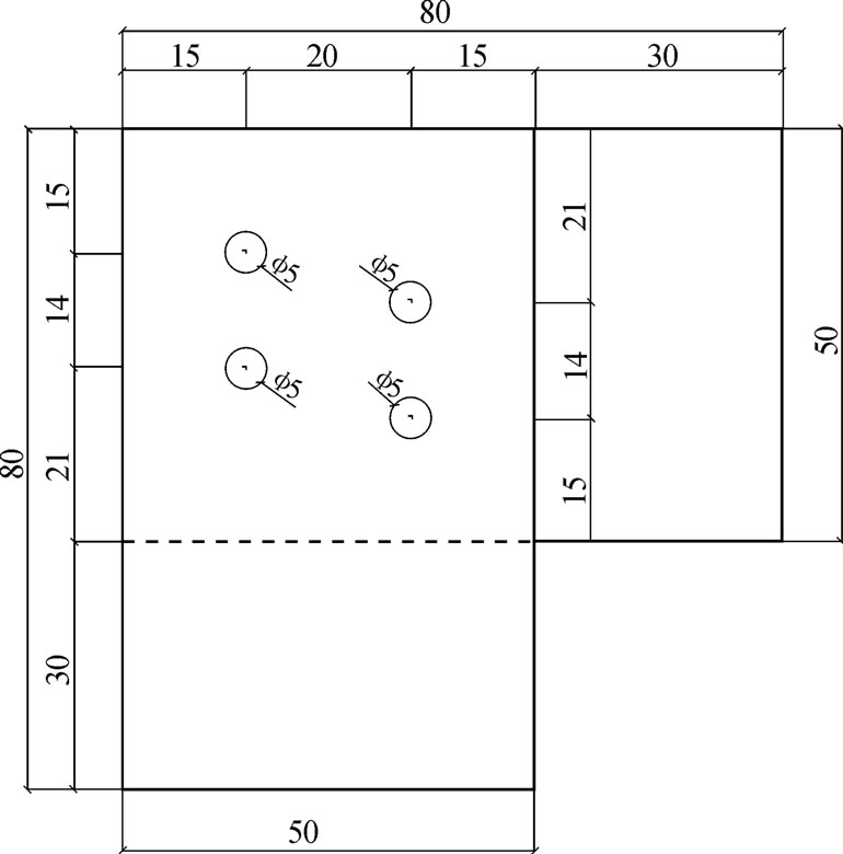
Figure 1. Experimental bolted joint sample

Figure 2. Macroscopic corrosion morphology under simulating industrial atmosphere
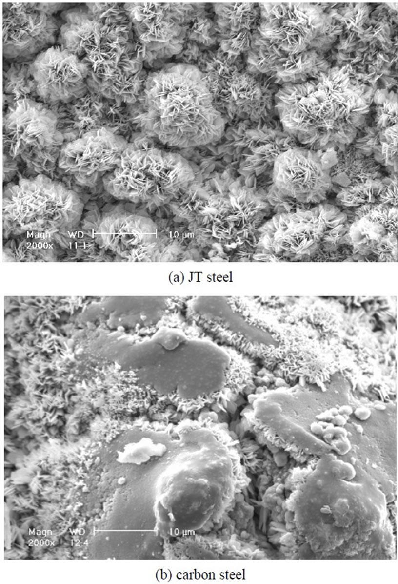
Figure 3. Microscopic corrosion morphology under simulating industrial atmosphere
The corrosion rates of the bolted joints of JT steel and common carbon steel are presented in Table 1. The corrosion rate of common carbon steel is about two times higher than that of the JT steel.
According to the analysis of the test results, the corrosion-resistant performances of the bolted joints of weathering steel and common carbon steel were compared. It shows that the corrosion degree of joint samples is higher than that of single chip samples, and the corrosionresistant performance of JT weathering steel is superior to common carbon steel. The corrosion resistant performance of JT steel is not worse than that of Corten series, which has been used in the transmission towers of American. The test results provide important reference and foundation for the extension and application of JT weathering steel in transmission towers.
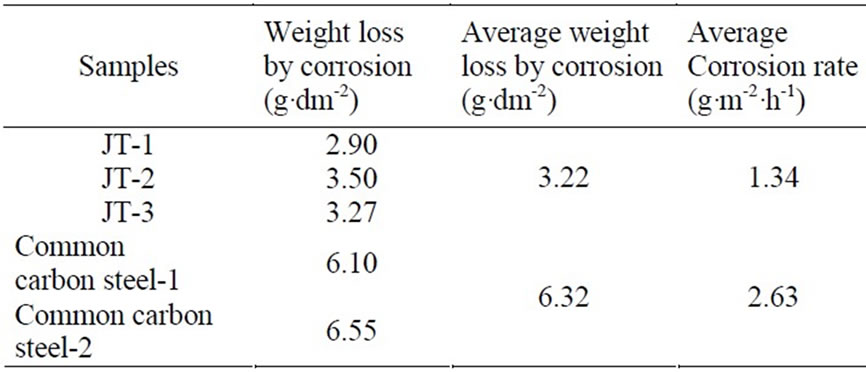
Table 1. Corrosion rates of the bolted joint samples
3. Application Study on Cold-Formed Steel
Cold-formed structures are mainly different from hot rolling steel structures in material molding style, which reflects the section and material property as well as the calculating theory [8,9]. Cold-formed steel member has the advantages of reasonable section shape, high integral stiffness and ultimate load. Cold-formed steel is suitable for tension and compression member, and the application of cold-formed steel makes full use of the material property and decreases the structural weight. Cold-formed steel can be machined in arbitrary dimension and shapes, and it may avoid the material waste in the fixed-length production of members. The reasonable sections of the members can be machined for different parts of a transmission tower. For example, the use of inequiaxial cold-formed angles for diagonal members can fully utilize the material property. In short, application of cold-formed steel in transmission towers will decrease steel consumption and acquire remarkable economic benefit.
As for solving the problems in the design method of cold-formed transmission tower, experimental and finite element analysis study on the design method for coldformed steel members in transmission tower has been carried out in this project, which includes experiments and numerical analysis on members and prototype tower. The weight and cost of cold-formed steel tower was compared with those of hot rolled steel tower when meeting with same loading conditions.
3.1 Experiments and Finite Element Analysis on Members
Sections of the tested members include equal angle and equal lipped angle. Load versus strain analysis was carried out for the tested members. As shown in Figure 4, equal angles and equal lipped angles are expressed by Lx-x-z and Lx-x-y-z, respectively, which x, y and z separately represent the length of leg, the length of lip and the thickness of angles. The section properties of angles are shown in Table 2.
Based on the applicable design specifications of transmission towers, the slenderness ratios of axial compression members are from 0 to 120, and the slenderness ratios and quantities of experimental members are given in Table 3.
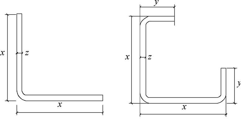
Figure 4. Types of member sections
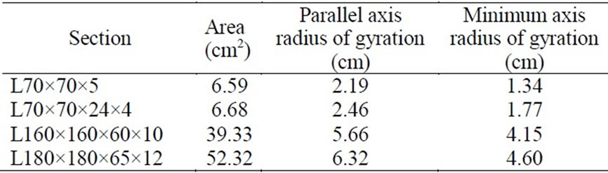
Table 2. Dimensions of tested sections
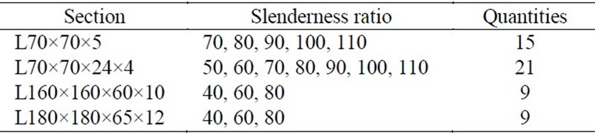
Table 3. Parameter description for tested members
The finite element program ANSYS was applied for the simulation of tested members. Four-node shell elements SHELL181 were used in this model. The SHELL181 element has six degrees of freedom at each node and is suitable for analyzing thin to moderatelythick shell structures. The element is well-suited for linear, large rotation, and large strain nonlinear applications. The finite element mesh size of 5mm×5mm (length by width) was used for the flat portions and a finer mesh size was used at the corners. Figure 5 shows the unreformed shape of a typical finite element mesh for an equal angle member and an equal lipped angle member.
It was stated in Young [9] that the residual stresses have a negligible effect on the ultimate load of the member. Hence, only initial overall geometric imperfections were considered in the finite element model. According to the Technical Code of Cold-formed Thin-wall Steel Structures (Ministry of Construction of People’s Republic of China), the initial overall geometric imperfections were considered by a sine curve with a magnitude of L/750 at the middle of the member.
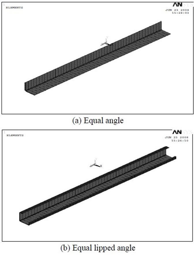
Figure 5. Finite element model
In the finite element model, the ends of the members were fixed in all degrees of freedom except for the translation in the direction of the applied load and the rotation around the longitudinal direction. The nodes other than at the two ends were free to translate and rotate in any direction. Static uniform loads were applied on centroid point of the loaded end, as in the experimental investigation. The nonlinear geometry parameter (*NLGEOM) was included to deal with the large deformation analysis in ANSYS.
As shown in Figure 6, a bilinear stress-strain curve for the flat and corner portions of members was applied in the analysis. Buckling modes and ultimate loads of the tested members were obtained by nonlinear buckling analysis.
The modes of buckling for tested members are presented in Figure 7. Load versus strain analysis was carried out for two sections of members with two slenderness ratios. The load versus strain behaviour of equal angle members and equal lipped angle members were obtained from the test results. For slender members, the behavior is symmetrical and the lips are in tension throughout the loading ranges. The heels of the sections of equal angle and equal lipped angle are always in compression indicating the neutral axis passed through the opposite corners. An unsymmetrical behavior is noticed in the case of stub members. It can be seen that the buckling mode of the slender members is flexure and that of the stub members is torsional-flexure. The ultimate loads of the tested members can be obtained by experimental analysis.
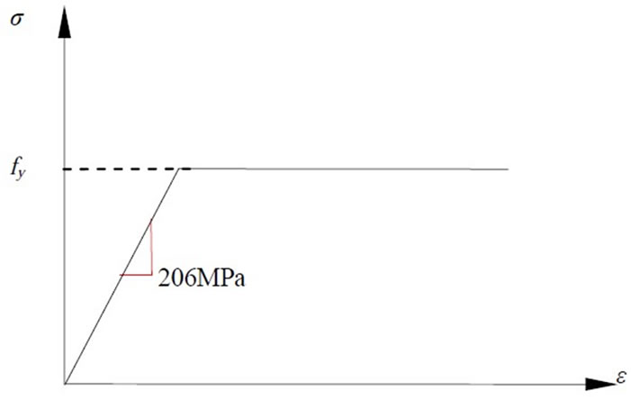
Figure 6. Stress-strain curve of the cold-formed steel
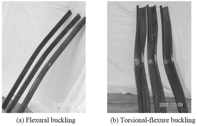
Figure 7. Buckling modes of tested members
Through the analysis of the experimental and analytical results, stability coefficient fitting curve and modification formulas of slenderness ratios for cold-formed members in transmission towers were determined. The ultimate loads calculating by the fitting curve are well agreed to the experimental values, especially for the members with small slenderness ratios. Some modification suggestions were proposed for the calculation of axial compression cold-formed angles.
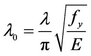
The minimum radius of gyration was used to determine the slenderness ratio ( ) of the tested member. For calculation of the stability coefficients, the nondimensional slenderness ratios (
 ) is given as:
 (1)
(1)
where  =yield stress and E=elastic modulus of coldformed steels.
According to the ordinary range of slenderness ratios in the Chinese Technical Regulation of Design for Tower and Pole Structures of Overhead Transmission Line [10] (NETC) and the American Design of Latticed Steel Transmission Structures, stability coefficient curve of the axial compression cold-formed members with different slender ratios from 10 to 250 was fit for the sake of convenience of engineering application.
With reference to the applicable division methods of the stability coefficient curve, the stability coefficient curve of cold-formed members was divided into three parts as 0< ≤1.2, 1.2<
 ≤2.5 and
 >2.5. Most nondimensional slenderness ratios (
 ) of the tested members were in the first part of 0<
 ≤1.2, and the other two parts of curves were fit by the finite element analysis results.
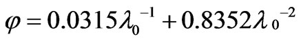
Expression of the fitting curves is given as follows.
For 0< ≤1.2
≤1.2
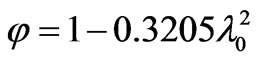 (2)
(2)
By the fitting of the results of finite element analysis, the other parts of expressions of the fitting curves were obtained and given as follows.
For 1.2< ≤2.5
≤2.5
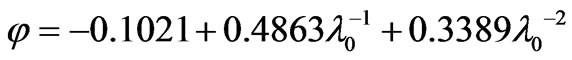 (3)
(3)
For >2.5
>2.5
 (4)
(4)
For the axial compression members with the slenderness ratios of 0 to 250, stability coefficients comparison of the fitting curves with the curves of applicable design standards for transmission towers is shown in Figure 8.
The yield stress of the members is 345MPa. It is noticed that the fitting curve is between the curves of the Chinese and American standards for the design of transmission towers, and the maximum variation is about 5%.
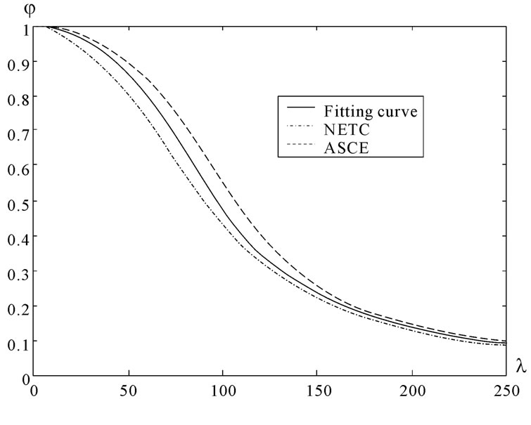
Figure 8. Comparison of stability coefficients
For different constraint conditions, the modification formulas of slenderness ratios are shown in Table 4.
3.2 Experiments and Numerical Analysis on Prototype Tower
According to the research results of cold-formed steel members, a 220kV prototype transmission tower using cold-formed steel was designed. For the convenience of weight comparison, the design conditions of the coldformed steel tower were the same with those of a typical hot-rolled steel tower.
1) After full-stress analysis of the cold-formed steel transmission tower under 68 load cases including wind load and broken load etc, 19 types of cold-formed steel were selected which shown in Table 5.
For checking the design methods of bearing capacity for cold-formed transmission tower, the prototype strength test of the 220kV tower was completed in the tower and pole test station of China Electric Research Institute. The test tower and longitudinal loading tower were shown in Figure 9.
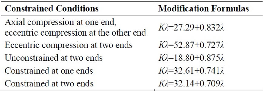
Table 4. Modification formulas
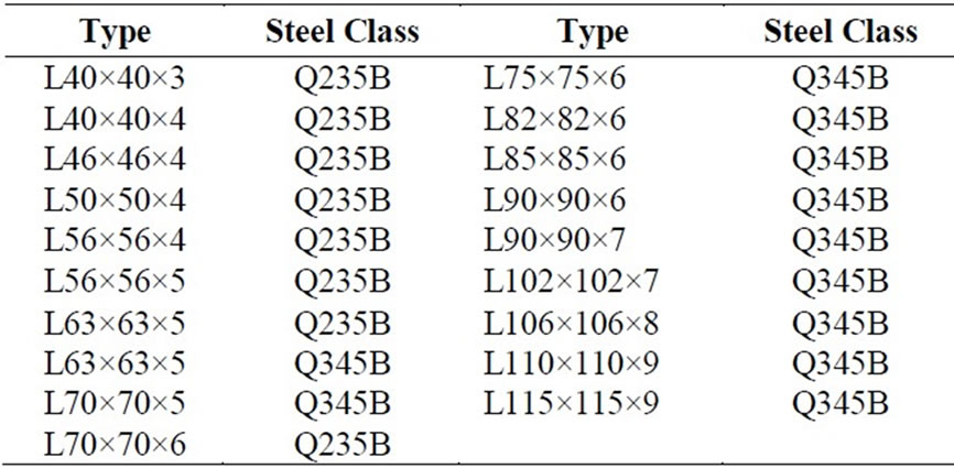
Table 5. Types of cold-formed steel for prototype tower
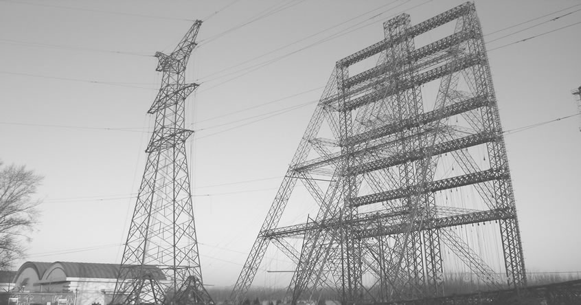
Figure 9. Test tower and loading tower
Eight testing load cases include wind load, broken load and installation load. Displacements of key points and strains of key members under different load cases were measured. The numerical analysis results especially the displacements meet well with those of experimental results.
Overloading case of this test is the load case under 60 degree wind. When the overloading percent reached 65 percent, the tower wasn’t destroyed. It shows that the cold-formed tower can meet the load cases, and it has much overage. The most important reason is that the design strength in numerical analysis is much less than the real yield strength of cold-formed steel. There is no upper limit for the strength classification of steel in China. The bearing capacity of tower structure can be enhanced greatly if the yield strength of cold-formed steel is much higher.
2) Weight comparison of cold-formed steel tower and hot-rolled steel tower is shown in Table 6. After using cold-formed steel, weight of the tower body and legs was reduced by 4.6 percent and 1.7 percent respectively, and the total weight of tower was reduced by 4.0 percent.
The strength enhancement of 10 percent by the cold forming effect was not considered in the design of transmission tower. The tests results show that the strength enhancement can be used. Weight of cold-formed steel tower can be reduced by more than 5% percent after considering the strength enhancement.
4. Conclusions
Application of weathering and cold-formed steel in transmission lines can reduce energy consumption and environmental pollution. Some advances in the studies on the weathering and cold-formed steel in transmission towers are introduced. Study on the application of weathering steel and cold-formed steel was completed in this paper.
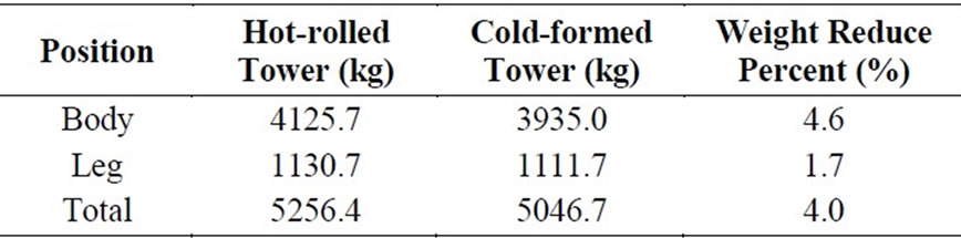
Table 6. Weight comparison
Firstly, corrosion-resistant tests of weathering steel samples under different simulating technical atmospheres were carried out separately for 240 hours. It shows that the corrosion degree of joint samples is higher than that of single chip samples, and the corrosion-resistant performance of weathering steel is superior to common carbon steel. The corrosion-resistance performance of weathering steel meets with the requirement of transmission tower.
Secondly, experiments and finite element analysis for cold-formed angles and a 220kV prototype tower were completed. According to the structural characteristics of transmission towers, four sections of cold-formed angles with different sections and slenderness ratios were selected in this study. The finite element model well predicts the buckling behavior of the cold-formed members. Experiments and finite element analysis for the ultimate loads of the compression cold-formed angles were carried out, and the load-strain curves as well as the ultimate loads of experimental members were obtained. The experimental ultimate loads were compared with those of calculated by the applicable standards, and it shows that the applicable standards aren’t adaptive to the strength design of compression cold-formed members of transmission tower in China. The stability coefficient fitting curve and modification formulas of slenderness ratios for cold-formed members in transmission towers were determined. The ultimate loads calculating according to the fitting curve are well agreed to the experimental values, especially for the members with small slenderness ratios. Some modification suggestions were proposed for the calculation of compression cold-formed angles, which provides important reference and basis for the application of cold-formed steels in transmission towers.
Finally, compared with the traditional hot-rolled steel transmission tower, application of cold-formed steel can reduce steel consumption by not less than 5 percent. The cost of the weathering and cold-formed steel transmission tower is equivalent to that of hot-rolled steel tower with hot galvanizing. So application of this new style steel can bring great social effects and economic returns.
5. Acknowledgment
This research was carried out within the science and technology project of State Grid Corporation of China. Name of the project is Study on the Application of Weathering and Cold-formed Steel in Transmission Tower. The project number is SGKJ [2007]117. The authors would like to thank the sponsor of State Grid Corporation of China.
REFERENCES
- C. H. He, “Feasibility discussion on application of high strength cold-formed section steel in transmission tower,” [J]. Steel Construction, 19(74), pp. 35-37, 2004.
- Beijing Electric Power Construction Research Institute of SGCC, “Study on the application on weathering steel and cold-formed steel in transmission tower [R],” Beijing, 2007.
- Ministry of Construction of People’s Republic of China, Chinese Technical code of cold-formed thin-wall steel structures: GB50018-2002 [S], Beijing, 2003.
- American Society of Civil Engineers, Design of Latticed Steel Transmission Structures: ASCE110-97 [S], USA, 1998.
- European Committee for Electrotechnical Standardization. Overhead electrical lines exceeding AC 45 kV: EN50341-1 [S], 2001.
- B. S. Gu, B. Wang, X. C. Ji, M. S. Xia, and J. H. Liu, “Study on Corrosion of JT245 Weathering Steel,” [J]. Journal of Steel and Iron Research, 17(6), pp. 55-58, 2005.
- F. L. Yang, J. K. Han, J. B. Yang, M. S. Xia, and Z. Y. Wang,“Study on corrosion-resistant performance tests of weather-proof steel node used in transmission towers,”[J]. Electric Power Construction, 29(9), pp. 23-28, 2008.
- S. J. Mohan, S. R. Shabeen, and G. M. S. Knight, “Behavior of cold formed lipped angles in transmission line towers,”[J]. Thin-Walled Structures, 44, pp. 1017- 1030, 2006.
- B. Young, “Experimental investigation of cold-formed steel lipped angle concentrically loaded compression members,” [J]. Journal of Structural Engineering, 131(9), pp. 1390-1396, 2005.
- National Economy and Trade Commission of PRC. Technical Regulation of design for tower and pole structures of overhead transmission line [S]. DL/T5154- 2002, China Electric Press, 2002.
NOTES
Sponsored by State Grid Corporation of China.