Int'l J. of Communications, Network and System Sciences
Vol.6 No.3(2013), Article ID:29146,6 pages DOI:10.4236/ijcns.2013.63018
Hybrid Mapping Scheme for Recent Orthogonal FDMA Schemes
Department of Electrical, Faculty of Engineering and Architecture, Ibb University, Ibb, Yemen
Email: faisalalkamali@yahoo.com
Received January 23, 2013; revised February 18, 2013; accepted March 13, 2013
Keywords: Subcarrier Mapping; Hybrid Scheme; SC-FDMA
ABSTRACT
Single-carrier frequency-division multiple access (SC-FDMA) and orthogonal frequency division multiple access (OFDMA) systems are new orthogonal multiple access systems. They have been adopted in the 3GPP long term evolution (3GPP-LTE). In these systems, there are only two types of subcarrier mapping schemes which are the interleaved and the localized. So, introducing a new subcarrier mapping scheme is an important issue, which is the main objective of this paper. In this paper, a hybrid subcarrier mapping scheme is proposed and examined for the SC-FDMA system. Monte Carlo simulations are performed to compare the performance of the proposed scheme with that of the interleaved and the localized schemes. It is shown that a hybrid scheme provides better performance than that of the localized and the same performance as that of the interleaved scheme and increased robustness to carrier frequency offset (CFO) at the expense of increased envelope fluctuations.
1. Introduction
Recently, orthogonal FDMA multiple access systems such as the SC-FDMA and the OFDMA are attracting much attention for the recent physical layer protocols in highspeed wireless networks due to theirs advantages over the conventional FDMA multiple access system. These multiple access systems have been employed for the physical-layer protocol in 3GPP-LTE [1].
In the literature, SC-FDMA has been studied with different basis functions [2,3]. However, only two subcarrier mapping schemes are considered: the interleaved subcarrier mapping scheme and the localized subcarrier mapping scheme [4]. In localized mapping, the discrete Fourier transform (DFT) outputs are mapped to a subset of consecutive subcarriers thereby confining them to only a fraction of the system bandwidth. In interleaved mapping, the DFT outputs of the input data are assigned to subcarriers over the entire bandwidth non-continuously, resulting in zero amplitude for the remaining subcarriers [4]. In this paper, we will refer to the localized SC-FDMA system as LFDMA, and the interleaved SC-FDMA system as IFDMA. The IFDMA scheme provides a low peakto-average ratio (PAPR), but at the cost of a higher sensitivity to CFOs and phase noise like the OFDMA system [5,6]. The LFDMA scheme is more robust to multiple access interference (MAI), but it incurs a higher PAPR than the IFDMA scheme [4].
In this paper, an efficient subcarrier mapping method, named Hybrid FDMA (HFDMA), is proposed which not only holds the same performance as the IFDMA scheme, but also overcomes its shortcomings. It also provides better performance than that of the LFDMA.
This paper is organized as follows: In the next section (Section 2), we will briefly introduce the SC-FDMA system model with the proposed scheme. In Section 3, the details of the proposed scheme will be explained. In Section 4, simulation results are given to verify the performance of the proposed scheme. Finally, conclusions are drawn in Section 5.
2. SC-FDMA System Model
The block diagram of the SC-FDMA system with the proposed scheme is shown in Figure 1. One base station and U uplink users are assumed. There are totally M subcarriers and each user is assigned a subset of subcarriers for the uplink transmission. For simplicity, we assume that each user has the same number of subcarriers, N. SC-FDMA system has much in common with the OFDMA system except for the additional DFT and inverse DFT (IDFT) blocks at the transmitter and receiver, respectively. For this reason, the SC-FDMA system is sometimes referred to as DFT-spread or DFT-precoded OFDMA system. The transmitter of the SC-FDMA system uses different subcarriers to transmit information
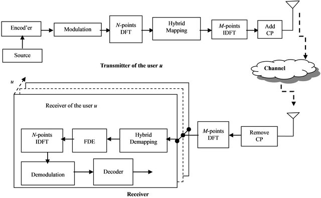
Figure 1. Structure of the SC-FDMA system over a frequency selective channel.
data, as in the OFDMA system. However, the SC-FDMA system transmits the subcarriers sequentially, rather than in parallel. This approach has the advantage of enabling a low PAPR, which is important to increase cell coverage and to prolong the battery lifetime of mobile terminals.
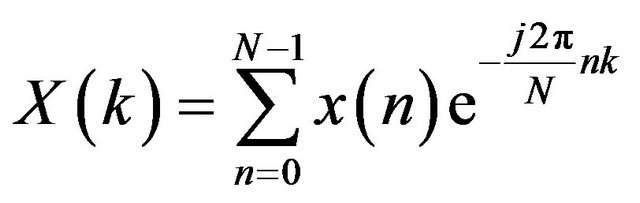
At the transmitter side, the encoded data is transformed into a multilevel sequence of complex numbers in one of several possible modulation formats. The resulting modulated symbols are grouped into blocks, each containing N symbols and the DFT is performed. The signal after the DFT can be expressed as follows:
 (1)
(1)
where N is the input block size.  represents the modulated data symbols. The outputs are then mapped using the hybrid mapping to
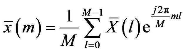
  orthogonal subcarriers. Then, the M-points IDFT are used to convert the output to a time domain complex signal sequence. M = QN is the output block size. Q is the maximum number of users that can transmit, simultaneously. Notice that the remaining M − N subcarriers may be used by the other users communicating in the cell, thus a promising multiuser access is achieved. The resulting signal after the IDFT can be given as follows:
 (2)
(2)
where represents the frequency domain samples after the subcarrier mapping scheme. Before transmission through the wireless channel, a cyclic prefix (CP) is appended in front of each block to provide a guard time preventing IBI in the multipath channel. After adding a CP of length NC to the resulting signal, the signal is transmitted through the wireless channel.
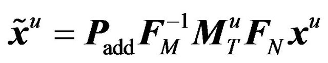
In matrix notation, the transmitted signal of the uth user  can be formulated as follows:
 (3)
(3)
where  is an N × 1 vector containing the modulated symbols of the
  user.
user.  is an N × N DFT matrix.
  is an M × M IDFT matrix.
  is an M × N matrix describing the subcarriers mapping of the uth user.
  is an
is an  matrix, which adds a CP of length NC. The entries of
  for both the LFDMA and the IFDMA systems will be given in Section (3).
  can be represented as follows:
 (4)
(4)
where
 (5)
(5)
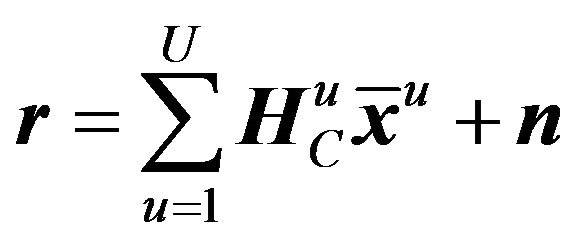
At the receiver, the CP is removed from the received signal and the received signal can be written as follows:
 (6)
(6)
where  is an M × M circulant matrix describing the multipath channel between the uth user and the base station.
  is an M × 1 vector representing the block of the transmitted symbols of the uth user before adding the CP. n is an M × 1 vector describing the noise. n contains independent identically-distributed (i.i.d) zero-mean additive white Gaussian noise (AWGN).
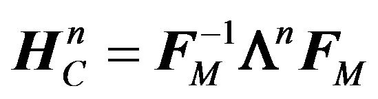
The circulant matrix  can be efficiently diagonalized by the DFT and the IDFT. It can be expressed as follows:
 (7)
(7)
where  is an M × M diagonal matrix containing the fast Fourier transform of the circulant sequence of
 .
.
The generic M-point DFT matrix has entries
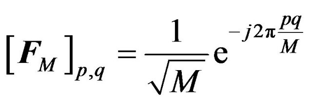 , and its inverse is
 .
.
Now, substituting (7) in (6) and apply the M-point DFT, we get
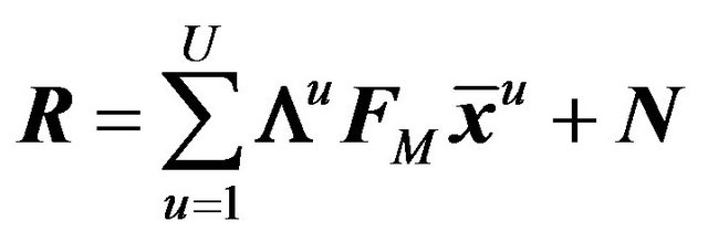 (8)
(8)
where N is the frequency domain vector of the noise. Figure 1 depicts the SC-FDMA receiver for the U users. One can see that for each user, a separate detection is performed. So, the detection process for the uth user will be only discussed for the rest of this section.
After that, the frequency domain equalization (FDE), the hybrid subcarrier demapping, and the M-point IDFT operations are performed to provide the estimate of the modulated symbols as follows:
 (9)
(9)
where  is an N × 1 vector containing the estimate of the modulated symbols.
  is an M × M matrix representing the FDE of the uth user.
  is an N × M subcarriers demapping matrix of the uth user.
  is given by taking the transport of
 , that is,
 .
.  can be derived according to the minimum mean square error criterion as follow:
 (10)
(10)
Finally, the demodulation and decoding processes are performed.
3. The Proposed HFDMA Scheme
DFT output of the data symbols is mapped to a subset of subcarriers, a process called subcarrier mapping. The subcarrier mapping assigns DFT output complex values as the amplitudes of some of the selected subcarriers. Subcarrier mapping can be classified into two types: localized mapping and distributed mapping. In localized mapping, the DFT outputs are mapped to a subset of consecutive sub-carriers thereby confining them to only a fraction of the system bandwidth. In distributed mapping, the DFT outputs of the input data are assigned to subcarriers over the entire bandwidth non-continuously, resulting in zero amplitude for the remaining subcarriers. A special case of distributed SC-FDMA is called interleaved SC-FDMA, where the occupied subcarriers are equally spaced over the entire bandwidth [4].
The proposed scheme is a hybrid scheme comprising the localized and the interleaved schemes. On the other hand, in the proposed scheme, the DFT outputs of the input data are first divided into subbands and each subband contains N1 symbols . These subbands are then assigned to subcarriers over the entire bandwidth. The number of subbands is
 . If the subcarrier mapping matrix of the uth user is denoted by
 , the entries of
  for both the localized and the interleaved schemes are formulated, respectively, as follows:
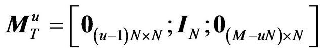 (11)
(11)
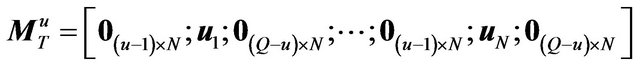 (12)
(12)
where the  and
and  matrices denote the N × N identity matrix, and the
  all-zero matrix, respectively.
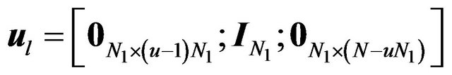
  denotes the unit row vector, of length N, with all zero entries except at l. The entries of
  for the proposed HFDMA scheme is expressed as follows:
 (13)
(13)
where
 (14)
(14)
When the number of symbols in each subbands is equal to 1, i.e. N1 = 1, (13) is reduce to (12) and the hybrid scheme becomes similar to the interleaved scheme. However, when the number of symbols in each subbands is equal to the outputs of the DFT, i.e. N1 = N, (13) is reduce to (11) and the hybrid scheme becomes similar to the localized scheme. In the hybrid scheme, the number of symbols in each subbands must be chosen carefully in order to obtain better performance.
Figure 2 shows the different subcarrier mapping schemes. This example assumes 2 users sharing 12 subcarriers. Each user has a block of six data symbols to transmit at a time. The DFT output of the data block has six complex frequency domain samples, which are mapped over 12 subcarriers using different mapping
 (a)
(a) (b)
(b) (c)
(c) (d)
(d) (e)
(e)
Figure 2. Subcarrier mapping schemes. (a) DFT ouputs; (b) Localized subcarrier mapping; (c) Interleaved subcarrier mapping; (d) Hybrid subcarrier mapping when the number of symbols in each sub-band is 2; (e) Hybrid subcarrier mapping when the number of symbols in each sub-band is 3.
schemes. Note that N1 = 2 in Figure 2(c) whereas N1 = 3 in Figure 2(d).
The hybrid mapping scheme have the advantages of both the localized and the interleaved schemes. The main advantages of the hybrid mapping scheme can be summarized as follows:
1) It is more robust with respect to frequency selective fading.
2) It offers additional frequency diversity gain similar to that in the interleaved scheme, since the information is spread across the entire system bandwidth.
3) It offers multi-user diversity in frequency selective channel conditions similar to that in the localized scheme.
4) It is more robust with respect to carrier frequency offset.
The main disadvantage of the hybrid mapping scheme is its high PAPR as compared to that of the localized and the interleaved schemes, but its PAPR is also lower than that of the OFDMA system.
4. Simulation Results
The performance of the proposed scheme is tested with computer simulations. An uplink SC-FDMA system with 512 subcarriers is considered. In this system, there are four users, and 128 subcarriers are allocated to each user. The users employ QPSK mapping for their data symbols. The channel model used for simulations is the vehicular A model [7]. It has six Rayleigh fading taps at delays of 0, 310, 710, 1090, 1730 and 2510 ns, with relative powers of 0 dB, −1 dB, −9 dB, −10 dB, −15 dB, and −20 dB, respectively. The vehicular A channel has a mobile speed of 120 Km/H. This speed corresponds to a Doppler spread of 223 Hz for a carrier frequency of 2 GHz. A convolutional code with rate 1/2, constraint length 7, and octal generator polynomial (133, 171) is used.
The impact of the number of symbols in each subband N1 on the bit error rate (BER) performance of the proposed scheme at different signal-to-noise ratio (SNR) values and QPSK modulation scheme is illustrated in Figure 3. We observe that the best choice of the number of symbols in the subband is N1 = 2. When N1 is greater than 2 the performance starts to degrade, especially at high SNR. Thus, N1 = 2 is appropriate choice and it will be used for the rest of experiments.
Figures 4 and 5 show the variation of the BER with the SNR at different modulation schemes for the IFDMA, the LFDMA, and the HFDMA systems, respectively. It is shown that the HFDMA system provides better performance than that of the LFDMA system and provides the same performance as that of the IFDMA system.
The complementary cumulative distribution function (CCDF) of the PAPR for the IFDMA, the LFDMA, the HFDMA, and the OFDMA systems are evaluated and shown in Figure 6 with QPSK modulation formats. Raised cosine filter, and 4 times oversampling are used. 105 data blocks are generated to calculate the CCDFs of the PAPR. No pulse-shaping was applied in the case the OFDMA system. It is clearly seen that, the HFDMA system has lower PAPR than the OFDMA systems by about 2.75, but higher than that of the IFDMA and the LFDMA systems by about 2.5 and 0.75 dB, respectively.
The impact of the CFO on the performance of the HFDMA is studied and shown in Figure 7. The system model of the SC-FDMA system in the presence of CFO
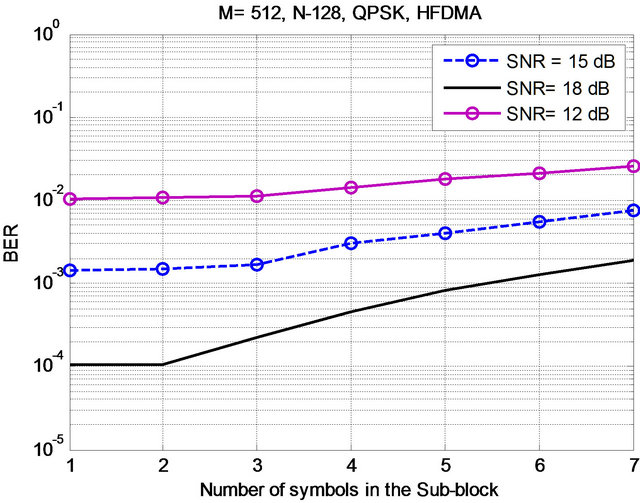
Figure 3. BER versus the number of symbols in the subblock for HFDMA system.
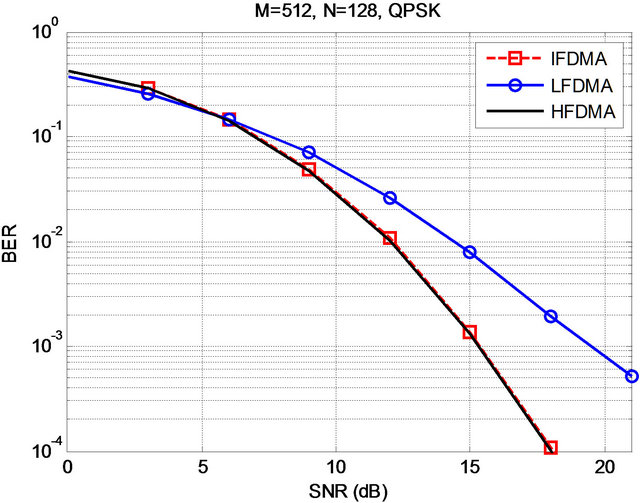
Figure 4. BER versus the SNR for the SC-FDMA system with different subcarrier mapping schemes.
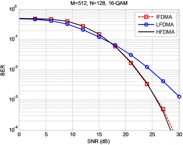
Figure 5. BER versus the SNR for the SC-FDMA system with different subcarrier mapping schemes.
is explained in our paper in [6] and this model is used in this experiment.
Figure 7 presents the variation of the BER with the maximum normalized CFO for the IFDMA, the LFDMA, and the HFDMA systems at SNR= 15 dB. Each CFO is a
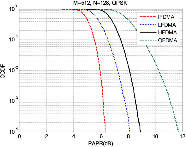
Figure 6. CCDFs of the PAPR of the SC-FDMA system with different subcarrier mapping schemes.
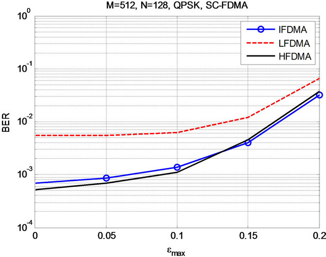
Figure 7. BER versus the CFO for the SC-FDMA system with different subcarrier mapping schemes.
random variable with uniform distribution in . Where
  is the maximum normalized CFO. The CFOs are chosen randomly to simulate a more practical scenario, similar to that in [6]. It is shown that the performance of all systems deteriorates when the CFOs increase, especially at high CFOs values. From this figure, it is clear that for small to moderate CFOs, the performance of the HFDMA system is better than that of the IFDMA and the LFDMA systems.
Figure 8 demonstrates the impact of the estimation errors on the performance of the HFDMA and the IFDMA systems at SNR = 20 dB. The estimated CFOs are obtained by adding a zero-mean independent Gaussian random variable to the true values of the CFOs.
The circular convolution method-based CFO compensation in [8] is considered here. The circular convolution is also discussed in [6]. The estimated channel impulse responses are also obtained in the same manner. This figure shows that the HFDMA scheme provides slightly better performance than that of the IFDMA scheme and the performance will be degrading as the estimation er-
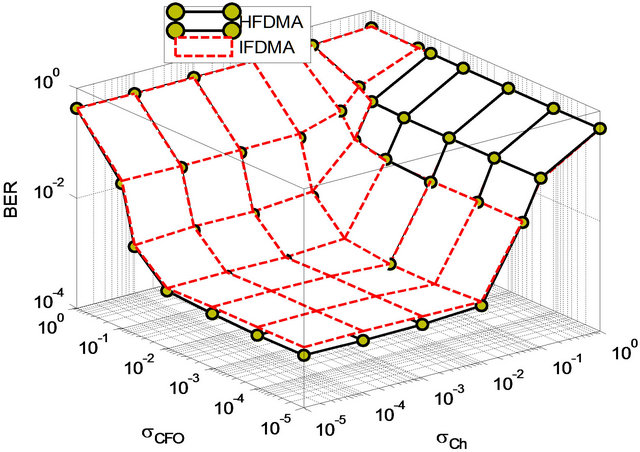
Figure 8. Variation of the BER of the IFDMA and the HFDMA systems in the presence of the estimation errors.
rors increased. It is clear that the performance of the proposed scheme starts to degrade as the standard deviation of the errors in the CFOs estimation  becomes greater than 0.01 and the standard deviation of the errors in the channel estimation
  becomes greater than 0.01. These limits can be satisfied with the estimation algorithms, which show the robustness of the proposed HFDMA scheme to estimation errors, especially, the CFOs estimation errors.
5. Conclusion
This paper has introduced a hybrid subcarrier mapping scheme for SC-FDMA system. Simulation results for uplink SC-FDMA system demonstrate the effectiveness of the proposed HFDMA scheme. It is clear that the HFDMA scheme provides a better BER performance than that of the conventional LFDMA scheme and the same BER performance as that of the IFDMA scheme. In addition, the HFDMA scheme is more robust to the CFO than that of the IFDMA and the LFDMA schemes. The implementation of the proposed HFDMA scheme requires a proper choice of the number of symbols in the subband to achieve a good BER performance. Simulation experiments have shown that a value of 2 is a suitable choice for this parameter. Simulation results also have shown that the PAPR of the HFDMA system is higher than that of the IFDMA and the LFDMA systems, but lower than that of the OFDMA system.
REFERENCES
- Air Interface for Fixed and Mobile Broadband Wireless Access Systems Amendment for Physical and Medium Access Control Layers for Combined Fixed and Mobile Operation in Licensed Bands, IEEE Std. 802.16e, 2006.
- H. G. Myung, J. Lim and D. J. Goodman, “Single Carrier FDMA for Uplink Wireless Transmission,” IEEE Vehicular Technology Magazine, Vol. 1, No. 3, 2006, pp. 30-38. doi:10.1109/MVT.2006.307304
- F. S. Al-kamali, M. I. Dessouky, B. M. Sallam, F. E. Abd El-Samie and F. Shawki, “A New Single Carrier FDMA System Based on the Discrete Cosine Transform,” Proceedings of the ICCES’9 Conference, Cairo, 14-16 December 2009, pp. 555-560.
- H. G. Myung and D. J. Goodman, “Single Carrier FDMA: A New Air Interface for Long Term Evaluation,” John Wiley & Sons, Ltd., New York, 2008. doi:10.1002/9780470758717
- F. S. Al-kamali, M. I. Dessouky, B. M. Sallam, F. Shawki, W. Al-Hanafy and F. E. Abd El-Samie, “Joint LowComplexity Equalization and Carrier Frequency Offsets Compensation Scheme for MIMO SC-FDMA Systems,” IEEE Transactions on Wireless Communications, Vol. 11, No. 3, 2012, pp. 869-873.
- F. S. Al-kamali, M. I. Dessouky, B. M. Sallam, F. E. Abd El-Samie and F. Shawki, “Uplink SC-FDMA System with Joint Equalization and Carrier Frequency Offsets Compensation,” IET Communications, Vol. 5, No. 4, 2011, pp. 425-433. doi:10.1049/iet-com.2010.0135
- 3rd Generation Partnership Project, 3GPP TS 25.101- Technical Specification Group Radio Access Network; User Equipment (UE) Radio Transmission and Reception (FDD) (Release 7), September 2007, Section B.2.2.
- J. Choi, C. Lee, H. W. Jung and Y. H. Lee, “Carrier Frequency Offset Compensation for Uplink of OFDM-FDMA Systems,” IEEE Communications Letters, Vol. 4, No. 12, 2000, pp. 414-416. doi:10.1109/4234.898725