Int'l J. of Communications, Network and System Sciences
Vol.6 No.1(2013), Article ID:27460,15 pages DOI:10.4236/ijcns.2013.61005
Scalable Incremental Network Programming for Multihop Wireless Sensors*
1Cisco Systems, San Jose, USA
2University of California, Berkeley, USA
Email: jajeong@cisco.com, culler@eecs.berkeley.edu
Received October 23, 2012; revised November 27, 2012; accepted December 7, 2012
Keywords: Network Programming; Incremental Update; Multihop Networks; Heterogeneous Images
ABSTRACT
We present a network programming mechanism that can flexibly and quickly re-task a large multi-hop network of wireless sensor nodes. Our mechanism allows each sensor node to be incrementally reprogrammed with heterogeneous images of native program code using Rsync block comparison algorithm, point-to-point routing with the BLIP IPv6 stack, and image volume management with Deluge2. With our re-tasking method, we demonstrate an order of magnitude speed-up on small code changes over non-incremental delivery. Our mechanism also scales sub-linearly in the diameter of the network. Collectively, these advancements qualitatively change the software life cycle of the embedded networked systems.
1. Introduction
In many systems, the ability to change code during deployment is a basic design requirement. PC operating systems and software packages are often updated with bug fixes, security patches, and performance improvements. Consumer electronics products such as cellular phones and set-top boxes are also updated with bug fixes and policy changes. The argument for re-tasking also applies to wireless sensor networks. While sensor network deployments are not expected to change as frequently as development networks, it is desirable that they have re-tasking capability for flexibility and maintenance purposes. The basic requirement for reprogramming a static sensor network installation is for the reprogramming system to function well in a multi-hop setting. With a proper network layer, this function is handled mostly transparently, and we can look at other needs: 1) native image; 2) heterogeneous images for different nodes; and 3) incremental re-tasking. Requirement 1) is for executing arbitrary program code, and not just a special type of script running on a virtual machine. Requirement 2) demands re-tasking each individual sensor node with a different image. Finally, 3) is an optimization for faster reprogramming by sending changes to the program image incrementally.
Many wireless re-tasking methods have been developed. These previous methods have focused on efficiently disseminating the same large program image to a large number of homogeneous devices throughout a large network. This paper takes a practical look at distributing code in a wireless sensor network using point-to-point networking. In this regard, our work is similar to reprogramming nodes in the Internet; code is downloaded and installed. We note that this method significantly increases flexibility at the cost of some efficiency. Our approach is the composition of several building blocks. We use the image volume management module of Deluge2 [1] which provides a volume manager and boot loader to allow in situ reprogramming of our embedded devices. We transfer the program image to a specific node over multiple hops by addressing the devices using an IPv6 layer with routing from the BLIP IPv6 stack [2]. Finally, we process the program image as differential updates in three steps—encoding, transport and decoding, and we generate the patch for the program image update using an unstructured block comparison method, Rsync algorithm [3]. With our wireless re-tasking method, we demonstrate a transport speed-up factor of 37.0 for changing a constant and 6.3 for adding a few lines of code when compared to the non-incremental delivery. With the overhead of encoding and decoding, we are able to get total programming time speed-up of 9.4 for changing a constant and 4.1 for adding a few lines of code. Our wireless re-tasking method scales well with the programming time increasing sub-linearly to the diameter of the network. The rest of this paper is organized as follows. In Section 2, we describe the concept of network programming and review previous work. We describe the design principles and the implementation details for our incremental network programming mechanism in Section 3 and 4. We evaluate the performance in Section 5 and conclude this paper in Section 6.
2. Background and Related Work
2.1. Background
Due to resource constraints, a wireless sensor node does not have enough computing power and storage to support rich programming environment found on a PC-scale machine; thus the program code is developed in a more powerful host machine and is loaded onto sensor nodes. In conventional embedded devices, the program code is usually injected into the program memory of a sensor node through the serial port that is directly connected to the host machine, and this programming method is called in-system programming. However, it requires a physical contact to each sensor node, and this is a hurdle when maintaining a large sensor network. For network embedded devices, we would like to reprogram them remotely over the network.
Instead of using direct injection, network programming uses an encode-transport-decode approach, which allows it to program a sensor node without requiring a physical contact. In the encoding stage, “program image reader” in the host machine reads the application program code and transforms it into packed binary format. Typically, the program code is represented as blocks of binary data, along with checksums included for verification purposes. In the transport stage, a “transfer program” on the host machine transmits the program image as packets, while the “listener” on the sensor node stores the received program code in the external flash memory. The program code is written to the external flash memory because the program code for most embedded controllers (MCUs) is stored in internal flash. It is generally not possible to rewrite the current image while running from it. In the decoding stage, a “verifier” in the sensor node validates the checksums in the received program image and instructs the boot loader to transfer the external program image to the program memory of the MCU. The boot loader is a small piece of code which sits at the beginning of program memory in the controller. It is responsible for selecting an image from the external flash and transferring it to the internal memory as required, and then transferring control to the new image.
2.2. Related Work
Previously, there has been a number of network programming schemes. These previous works can be categorized depending on how they handle the three steps of network programming—encoding, transport and decoding. First, a network programming scheme can be either single-hop [4] or multi-hop [5-8] depending on its transport mechanism: a single-hop network programming scheme transmits the program code to sensor nodes that can be directly reached in a single-hop, whereas a multihop network programming scheme propagates the program code to multiple nodes using an underlying network and transport protocol. A single-hop network programming scheme is relevant only for a small network; in a large network, a node can be more than two hops away from the base station and cannot be programmed. Multi-hop network programming schemes can be divided into two groups depending on their transmission mechanisms: bulk transport protocol [5,6,8,9] and point-topoint protocol [7]. A bulk transport protocol disseminates the program image to multiple nodes, using some form of multicast. The challenge for such a protocol is to transmit a program image to multiple nodes while not causing network congestion. Typical approaches are to use either epidemic protocols [6,9], a sender selection algorithm [8], or a sliding window protocol [5]. The other group of multi-hop network programming schemes is a point-to-point or unicast transport protocol. While a bulk transport protocol efficiently programs all the nodes in the network, it is not typically suitable for programming different groups of nodes with different program images. A point-to-point transport protocol sends the program image to a specific node using an underlying transport protocol.
Second, the program code that is transmitted by a network programming scheme can be either native code [4], [5,6], virtual machine (VM) code [9,10] or both native and VM code [11]. A native code reprogramming scheme allows a sensor node to run any program code that runs on the node natively. One drawback of native code reprogramming, especially on the platform that does not support dynamic linking (e.g. TinyOS), is that its transmission time is relatively long because it has to transmit the whole program image, which includes the common system code as well as the application code. A virtual machine reprogramming scheme improves the programming time by transmitting only the relevant code with no need to send the common system code, but it also has a drawback in that it lacks generality (running virtual machine specific code) or has a performance overhead (translating the native code). Third, a network programming scheme can send either the whole program image [4-6] or the incremental difference of the program image [11-16]. Transmitting the incremental difference of the program image can reduce programming time when a new version of program image overlaps with much of a previous version of program image. Previous works addressed incremental network reprogramming by individual address patches [13], address indirection [11,12,14, 16-18] or unstructured block comparison [3,15,19].
A version of an individual address patch algorithm was developed by Reijers et al. [13]. It generates an edit script that consists of primitive operations such as “copy”, “insert”, “address repair” and “address patch”. These operations help reduce the network traffic by modifying the program code at the instruction level, but have a few drawbacks. First, it depends on the instruction-set of a specific micro-controller (in his case, the Texas Instruments MSP430) and may not support evolving generations of sensor network platforms. Second, modifying program code at the instruction level increases flash memory accesses. An address indirection method [11,12,14] avoids modifying program addressed at instruction level by introducing a level of indirection for program addresses. This method divides the program address space as fixed-size chunks, allocating each function at the beginning of a chunk, and redirects any access to a function through a function address table. Thus, it reduces the chance of changing the address field of an instruction when program code is shifted. The cost of an address indirection method is a dynamic linker that is tailored to the instruction set architecture of a specific micro-controller. An unstructured block comparison method, such as Rsync [3] or LBFS [19], generates the difference of two program images by treating program image as binary data without assuming any structure on the program code. Rsync is a mechanism that efficiently synchronizes the remote copy of an arbitrary binary file over a low-bandwidth, bidirectional communication link. Rsync finds any shared blocks between the two files. If we naively compare the blocks of the two files at each byte position, the cost of comparison would be high. Rsync addresses this problem by having two levels of hash (checksum, hash). To compare two blocks, the algorithm first compares the checksum values of the two blocks. Only when the checksums match does the algorithm compare the hash value to ensure the correct match.
Our network programming mechanism supports pointto-point multi-hop transport, native code dissemination and incremental delivery. Unlike previous approaches, we generate the program code difference by comparing the program code at block level without any prior knowledge of the program code structure. This gives a general solution that can be applied to any hardware platform. Table 1 summarizes the different network programming schemes for wireless sensor network.
3. Design
In designing an incremental network programming mechanism, we need to consider several factors that affect the system performance. First, performance asymmetry of a sensor node and the host machine is critical. In dividing the roles of a sensor node and the host machine, we want sensor nodes to process only the key operations in an inexpensive way and push complexity to the host machine. For example, encoding can be complex, but decoding must be simple, robust, and require little storage. Second, bandwidth is scarce so transmissions should be minimized. With network programming, a large portion of the total time and energy spent is consumed transmitting the program image. Third, the locality of flash memory accesses should be maximized. Network programming stores the program image in the external flash memory. While the external flash memory has a large memory space, it has a limitation in that it should be accessed in blocks. Random access to individual bytes of the external memory is more costly than a sequential access because a block for the corresponding bytes should be accessed each time. Thus, accesses to the external flash memory should be organized to preserve locality.
Figure 1 illustrates the stages for incremental network
Table 1. Comparison of network programming schemes.
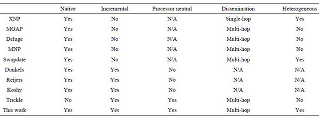
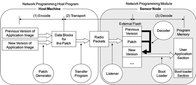
Figure 1. Incremental network programming stages.
programming: encoding, transport and decoding. In the encoding stage, the patch generator reads the previous and new versions of the program image and creates a patch. A patch is a list of commands that tells which blocks should be copied from the previous version and which blocks should be inserted as new data blocks to generate the new binary image. Generating a patch is a costly operation and we decided to place this functionality at the host machine. We can assume that we have a record of which version of the program image each node has. This is a reasonable assumption because most sensor networks are maintained by either a network administrator or a centralized job submission system to avoid contention among multiple users from simultaneous node reprogramming requests. In the transport stage, the transfer program transmits the patch as radio packets on the host side, then the listener program on the mote side receives these packets and stores them in the external flash memory. While we may decode each packet in the patch on the fly, we decided not to do so to optimize the transmission time and flash memory accesses. Instead, the transfer program treats the patch as a single large block and divides it into fragments of largest possible packet size before transmitting the patch. This helps reduce the transmission time compared to sending each patch command separately. This approach also optimizes flash memory accesses by storing the received patch blocks sequentially. In the decoding stage, the decoder generates the new program image by applying the patch to the previous program image. After verifying the generated program image, the decoder can call the boot loader, which transfers the program image to program memory and reboots with the new program image.
In the following subsections, we describe the mechanism of incremental network programming in detail for each stage.
3.1. Encoding: Generating a Patch
The encoding stage is done in two steps: first it generates a patch; then it builds an image volume. In the patchgeneration step, the patch generator reads the two program images (previous and new) and compares them in blocks, issuing either a copy or upload command per block. A copy command is issued when the blocks of the two program images are the same, meaning that the decoder can regenerate the block in the new version by copying the data bytes from the previous version. An upload command is issued with data bytes when the blocks are not the same.
In comparing blocks of the two program images, we need to consider the following factors: block size, scanning and block comparison. As for the block size, we use fixed-size blocks. This is because transport and decode stages expect fixed-size data for data transmission and flash memory access, and using fixed-size blocks allows data to be handled more efficiently on the mote side. As for the scanning, we scan the previous version in fixedsize blocks and the new version in bytes. This allows us to retain blocks of code in the new version even though the blocks are shifted by an arbitrary offset. As for the block comparison, we use a probabilistic method using two-level fingerprints: a weak checksum and a strong hash; a weak checksum has some chance of producing false positive, but it can be calculated fast; a strong hash requires more computation time, but its chance of generating false positive is very small and practically zero. First, the block comparison routine checks the weak checksums of the two blocks. Only when the weak checksums are the same, does it check the strong hashes. This approach can quickly eliminate non-matching cases while not losing accuracy. Based on these considerations, we decided to use a block comparison algorithm like Rsync [3]. This algorithm works in three steps, fingerprint generation, block comparison and patch compression.
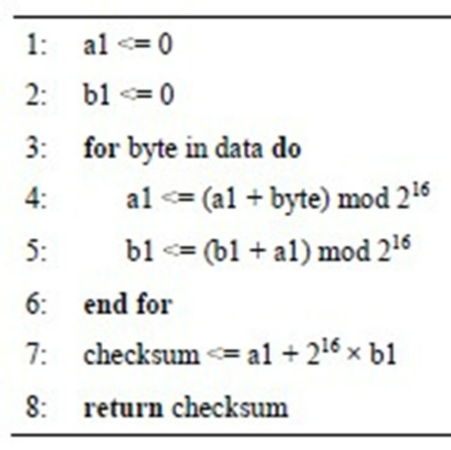
Fingerprint Generation: The fingerprint generation algorithm (Algorithm 1) calculates a checksum and a hash for each fixed-size block in the previous program
Algorithm 1. Fingerprint generation.
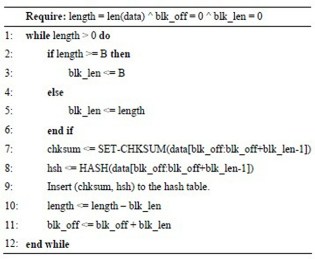
image. Then, it inserts the checksum pair into a hash table.
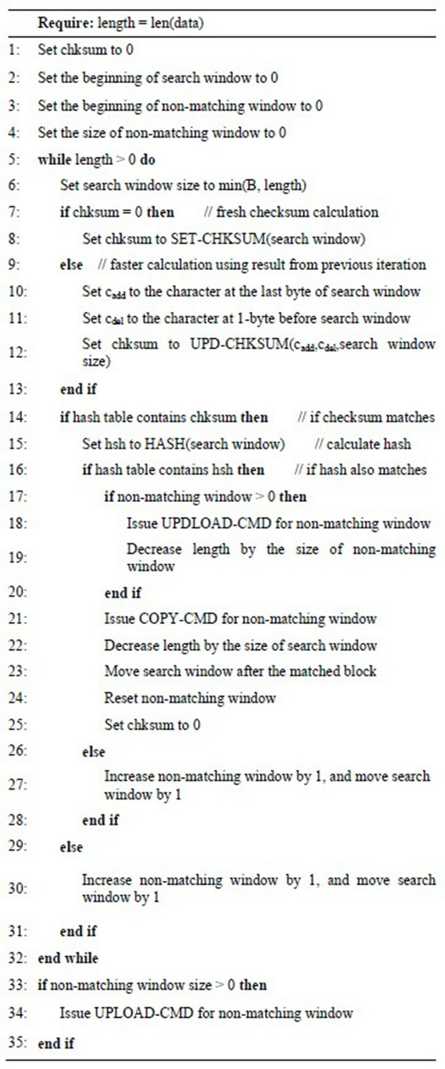
Block Comparison: In order to scan the new program image and find matching blocks, the block comparison algorithm maintains two data structures: search window and non-matching window. The search window is an area of the new program image to check the weak checksum and the strong hash (maintained by block offset blk_off and block length blk_len). The non-matching window is an area that has already been searched but does not contain any matching blocks from the previous program image (maintained by start index bn and end index en).
The block comparison algorithm (Algorithm 2) works in the following sequence. Initially, the search window is set to the first B-byte of the new program image and the non-matching window is set to null, where B is the default search window size (Initial condition). The algorithm calculates the weak checksum for the search window, and it also calculates the strong hash if the hash table has a match for the weak checksum (lines 6-14). If the hash also matches, the algorithm issues an upload command for any pending blocks in the non-matching window and issues a copy command for the search window (lines 15-22). If neither the checksum nor the hash matches, the algorithm shifts the search window and increases the size of non-matching window (lines 23-28). After finishing the scan of the new program image, the algorithm issues an upload command for any data in the non-matching window (lines 30-32).
As for the checksum algorithm, we use a rolling checksum algorithm such as the Adler-32 checksum [20]. A rolling checksum has a property that the checksum over a byte string can be calculated using the checksum from the previous iteration. This makes the checksum calculation a constant time operation once the checksum for the previous iteration is available. Without this prop
Algorithm 2. Block comparison.
erty, the time to calculate each checksum increases in proportion to the block size B. SET-CHKSUM() and UPD-CHKSUM() are rolling checksum calculation algorithms. They are similar to Adler-32 except that they use 216 instead of a prime number for modulo operation. SET-CHKSUM() calculates a rolling checksum when there is no previous checksum (Algorithm 3), and UPDCHKSUM() calculates a rolling checksum using previous checksum (Algorithm 4). As for the hash algorithm, we use the MD5 hash algorithm [21].
3.2. Patch Compression
The patch generated by the original Rsync algorithm (fingerprint generation and block comparison steps) is much smaller than the new program image, but it still has room for improvement. The original Rsync algorithm compares the program image blocks in fixed size and generates a list of copy and upload commands depending on whether the block in comparison has a matching copy or not. With this approach, there may be more copy commands than it is necessary because many blocks may be unchanged. For further optimizing the patch size, we compress the patch generated by the original Rsync algorithm by coalescing multiple consecutive copy commands into a single copy command. It processes an issued command in buffering, combining and flushing steps instead of writing the issued command directly to the program image as the original Rsync algorithm does.
• Buffering: An issued copy command is stored in the buffer instead of being written to the program image directly.
• Combining: A newly issued copy command is combined into the previously issued copy command if they are in consecutive addresses.
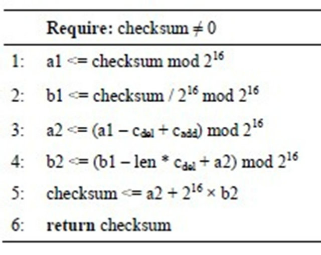
Algorithm 3. SET-CHKSUM(data): A function that calculates a rolling checksum.
Algorithm 4. UPD-CHKSUM(cadd, cdel, len): A function that updates the rolling checksum.
• 
• Flushing: The buffered copy command is flushed into the program image if the newly issued command is a copy command that is not in the consecutive address with the previously issued copy command or it is an upload command.
3.3. Encoding: Building an Image Volume
After the patch-generation step, the encoding stage transforms the patch into an image volume. The image volume is a binary image format in which the program code is represented in the external flash memory, and it is also the format that can be understood by the decoder. While an image volume can be in any format, we used a format that TOSBOOT, the standard boot loader for TinyOS 2.0, expects [1]. A patch image volume consists of the following components: data block, identifying header, CRC header and zero padding.
The data block is a sequence of UPLOAD and COPY commands for the patch. An UPLOAD command is encoded as a multiple of 16-bits and contains the following fields: command sequence number, command type, offset in the new program image, data length in bytes, and data. In case the data field is not a multiple of 16-bits, it is zero-padded to fit the 16-bit boundary. A COPY command is encoded as a 16-bit value that contains the following fields: command sequence number, command type, offset in the new program image, data length in bytes, offset in the previous program image. The TOSBOOT boot loader expects the length of the data block to be a multiple of page size (=1104 bytes). To make the data block compatible with the boot loader, we zero pad the data block to make the size of the data block a multiple of the page size. The identifying header in a 128-byte header contains information that can identify each program. For incremental network programming purposes, we use the following fields:
• username: normally, the user name who created the program image, set to “tos-build-patch” for the incremental network programming.
• hostname: normally, the host name where the program image is created, set to “tos-build-patch” for the incremental network programming.
• userhash: normally, the hash over the entire program image, set to the number of COPY and UPLOAD comands for the incremental network programming.
The CRC header is a 256-byte header that can contain up to 128 16-bit CRC values. i-th CRC value is a checksum over i-th page in the data block.
3.4. Transport
In the transport stage, the patch image volume is transmitted to the node to be reprogrammed over the radio. For transmitting the patch image volume, we divided the roles between the underlying best effort delivery and our reliable application level protocol. We use the User Datagram Protocol (UDP) of the BLIP IPv6 stack [2] and rely on it for routing and link-level transmission. Our application-level protocol handles fragmentation and reliable delivery. It divides the patch image volume into fragments so that each fragment can fit within the maximum packet size. Then, it delivers the fragment in a reliable way using end-to-end acknowledgments and retransmissions. As the underlying transport protocol, the Transmission Control Protocol (TCP) might have been used for its native support of reliable transmission, but we decided to use UDP for its smaller memory footprint and faster transmission. On the host machine, the transport protocol works as follows. It forms a network programming request packet for each fragment, and transmits the packet through the underlying best effort delivery. After sending the request packet, the applicationlevel protocol waits for the network program reply packet from the destination node. If the reply is not successful or not received within a timeout, the application-level protocol retransmits the request up to two times. We found this is sufficient for achieving reliable delivery of the patch image volume. The network program request and reply packets have an image field. This is to allow a user to specify in which volume the patch image will be stored. On the mote side, the application-level protocol stores the fragment in the external flash memory each time it receives the network program request packet.
3.5. Decoding
In the decoding stage, the decoding program on the mote side regenerates the new program image by applying the patch image to the previous program image. The decoding algorithm is described in Algorithm 5. For each command from the patch volume, the algorithm copies
Algorithm 5. Decoding algorithm.
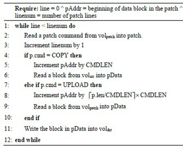
data block from either the previous program image volume or the patch image volume depending on the command type, and it writes the data block to the new program image volume. The image that is generated in the new program image volume has the same format as the program image transferred by non-incremental network programming. For verification purposes, we can check the CRCs for the newly generated program image. We can execute the new image by passing the index for the new image to the boot loader.
4. Implementation
4.1. Platform
As for the mote hardware, we use the TelosB platform [22] because it is being used widely and the current version of TinyOS supports a boot loader for this mote platform. While we chose the TelosB platform for our experiment, our incremental network programming scheme can be readily applied to other platforms such as MicaZ and Mica2 which are supported by the current version of TinyOS for node reprogramming. As for the system software, we use TinyOS 2.1 with Deluge2. Deluge2 [1] is a non-incremental network programming module that supports node reprogramming and multi-hop bulk code transfer. We formatted the image volume in the same ways as Deluge2 does so that we can reuse the boot loader and the program image hex file parser. As for the networking software, we use the BLIP IPv6 stack [2], which is an open source implementation of the 6LoWPAN protocol and it allows IPv6 packets to be sent over the low power wireless link using header compression techniques. The BLIP IPv6 stack supports routing and reliable delivery through link-level retransmissions. As a transport protocol, it supports UDP (User Datagram Protocol), which is a simple transport over the routing layer with the ability to address a port number. The ramifications of using b6LoWPAN stack are that each node can be reprogrammed with a unique image due to its support of any-to-any routing and that our implementation can be readily combined with other IP-based software tools.
One implication of using above platforms is the memory organization of the external flash memory. Assuming that the maximum size of an image volume is 48 KB for the TelosB mote, the Deluge2 on the TelosB mote divides the external flash memory of 512 KB into ten volumes. Thus, an image volume field in a network programming request/reply packet or a network programming decode command should be set to a valid volume index (0 through 9).
4.2. Implementation
On the host side, we wrote two applications in Python: tos-build-patch and tos-nwprog-patch. tos-build-patch generates the patch image for the two given images (previous and new). We implemented the Rsync algorithm and the Adler-32 like rolling checksum to generate the patch image. tos-nwprog-patch is a wrapper program that transmits the patch image to the mote using the BLIP IPv6 stack. In order to send a possibly large image reliably, we implemented fragmentation, end-to-end acknowledgment and retransmission. In general, the image size of the generated patch is shorter than that of the new program image for a small-scale change in the program code. However, this may not be true depending on the amount of change in the program code or the layout in the binary image. In such a case, blindly reprogramming a node with the patch can take longer time than reprogramming with the new image. To ensure that reprogramming time is no longer than that with the new program image, tos-nwprog-patch determines whether to transmit the patch or new program image by comparing the size of the patch and that of the new program image.
On the mote side, incremental network programming is handled by the following modules: user interaction module, image transmission module, verification module and patch module. The BLIP IPv6 stack provides a shell as a user interaction utility. This shell is a simple command interpreter that parses an IPv6 packet sent to the shell port (61616) and processes a corresponding command such as list, erase, verify and patch. We use a listener for image transmission. This module parses IPv6 packets sent to the network programming port (5213) into fragments and store them in the external flash memory. The verification module is called by the shell, and it verifies the specified volume by checking the CRCs. The patch module is also called by the shell and recreates the new program image by applying the patch to the previous program image. The implementation is summarized in Figure 2.
4.3. Code Complexity
On the host side (Python application source code):
• Non-incremental: 11.9 KB with 374 lines;
• Incremental: 28.8 KB with 893 lines.
On the mote side (nesC application binary image):
• Non-incremental: 41.7 KB ROM and 5.0 KB RAM;
• Incremental: 44.0 KB ROM and 5.8 KB RAM.
5. Evaluation
5.1. Experiment Setup
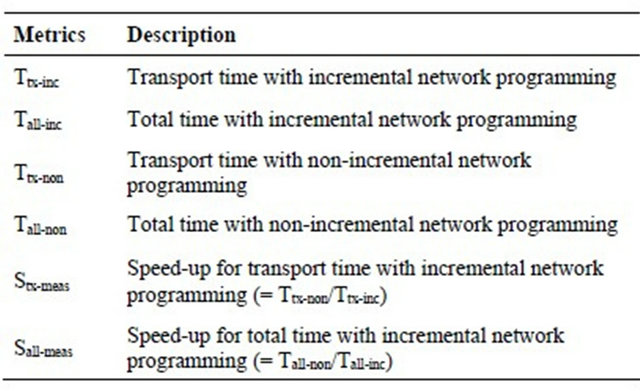
In order to evaluate the performance of our design of incremental network programming, we measure the time for data packet transmission Ttx-inc (only for the transport stage) and the time for total programming time Tall-inc (for encode, transport and decode stages). As a baseline for comparison, we also measure the times with non-incremental network programming: Ttx-non and Tall-non. From the measurement above, we can calculate the speed-ups for data packet transmission time and for total programming time: Stx-meas and Sall-meas. To validate the performance improvement, we can compare it with the estimation Stx-est. The estimation and measurement metrics are summarized in Table 2. As test cases, we consider the following five scenarios:
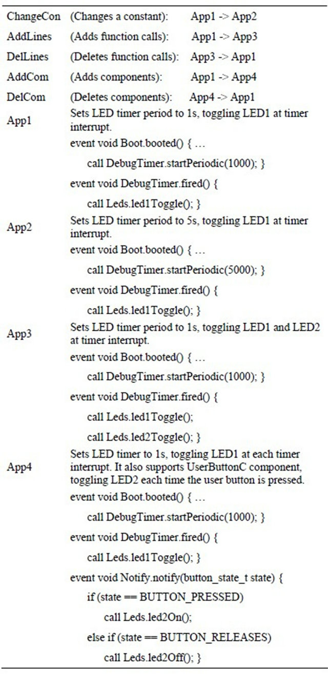
• ChangeCon : Changes a constant;
• AddLines : Adds function calls;
• DelLines : Deletes functional calls;
• AddCom : Adds components;
• DelCom : Deletes components.
Each scenario is described by a change from a test application App-i to another test application App-j. These test applications (App-1, 2, 3 and 4) have an incremental network programming capability with a few variations. The test scenarios and the test applications are described in Table 3.
5.2. Speed-Up Estimation and Effect of Block Size
To evaluate the effectiveness of incremental network programming, we have estimated the possible speed-up of transport time by comparing the size of the patch with
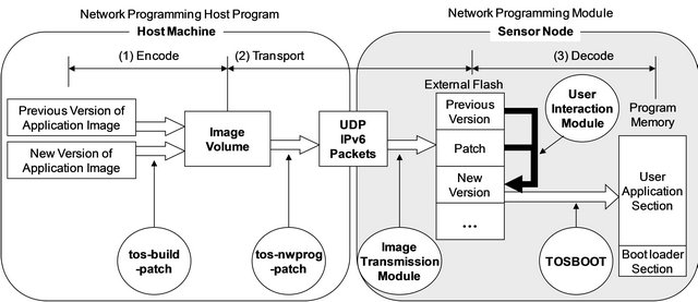
Figure 2. Implementation of incremental network programming.
Table 2. Evaluation metrics. (a) Estimation metrics; (b) Measurement Metrics.
(a)
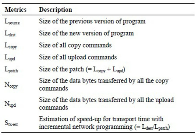
(b)
the size of new program image for each evaluation scenario. While estimating the speed-up of transport time, we also vary the parameters for incremental network programming, block size for patch generation, to find the optimal conditions.
5.2.1. Estimation of the Speed-Up of Transport Time
We estimated the speed-up of transport time with incremental network programming Stx-est, which is defined as the ratio of the block size of non-incremental delivery (Ldest) over the block size of incremental delivery (Lpatch): Stx-est = Ldest = Lpatch. For this, we ran the patch generation program for different test scenarios and patch block sizes, counting the number of bytes for the upload and copy commands. And we compared this with the number of bytes for the non-incremental delivery. Figure 3(a) shows the trends of image size for incremental delivery (Lpatch) and non-incremental delivery (Ldest). Figure 3(b) shows the estimation of transport time for incremental delivery (Stx-est). From the estimation results we can observe the following.
First, our incremental network programming has huge benefits for small changes. Its transport time speed-up is
Table 3. Test scenarios and applications being used.
a factor of 122.4 with a constant being changed (Change Con with block size 96), and it is a factor of 7.3 with a few lines being added or deleted (AddLines and DelLines with block size 32). Second, the improvement of our network programming is modest for big changes but it is still beneficial. When components are added or deleted, the transport time speed-up is a factor of 1.4 (AddCom and DelCom with block size 32). Third, each incremental network programming scenario has an optimum point for the block size B where the transport time speed-up is maximized: (B, Stx-est) = (96, 122.4), (32, 7.3), (32, 7.3), (32, 1.4), (32, 1.4) for ChangeCon, AddLines, DelLines, AddCom and DelCom.
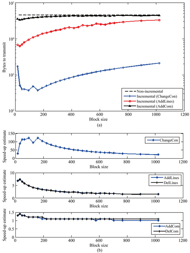
Figure 3. Estimation of patch image size and speed-up of transport time. (a) Plot of image size for non-incremental delivery and incremental delivery scenarios is plotted; (b) Plot of the estimation of speed-up of transport time Stx-est for nonincremental delivery scenarios over non-incremental delivery. This graph is taken by taking the ratio of the image size with non-incremental delivery over the image size with incremental delivery.
5.2.2. Trends of Percentage of Matches and Copy Command Cost
The reason why ChangeCon, AddLines, and AddCom have different trends for the speed-up of transport time can be explained by the trends of percentage of matches and copy command cost, as shown in Figure 4.
From the percentage of matches graph in Figure 4(a), we can observe the following: ChangeCon has a very high matching rate and it decreases slightly as the block size increases (99.7% down to 95.4%), thus this scenario can be benefited by incremental network programming over a wide range of block sizes. Whereas, AddLines is very sensitive to the block size, and its matching rate changes by a large amount from 91.4% to 27.9% as the block size increases. AddLines prefers a smaller block size because its matching rate decreases a great deal as the block size increases. DelLines has a small matching rate (less than 43%) and the matching rate gets even smaller to around 5% as the block size increases. Thus, due to the small matching rate, this scenario is not benefited by incremental network programming. The second graph (Figure 4(b)) shows that all three scenarios have
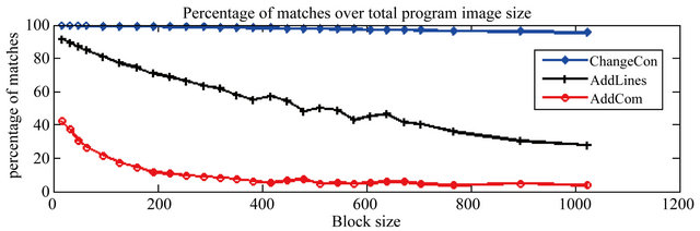 (a)
(a)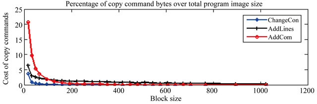 (b)
(b)
Figure 4. Percentage of matches (Ncopy/Ldest) and percentage of copy command bytes (Lcopy/Ldest) over the total image size for different test scenarios.
very similar trends in the cost of copy commands: the cost of copy commands decreases hyperbolically as the patch block size increases.
We can see that the percentage of matches (Figure 4(a)) favors a smaller block size for higher matching rate whereas the percentage of copy commands (Figure 4(b)) favors a larger block size for smaller cost of copy commands. This explains why ChangeCon and AddLines has a maximum point for the speed-up of transport time. The difference of ChangeCon and AddLines is the trend of matching rate. As the block size increases, the matching rate for ChangeCon decreases slightly while the matching rate for AddLines decreases faster. Thus, AddLines has its maximum point at a smaller value of B than ChangeCon does.
5.3. Measurement Results
In order to measure the performance of the multihop incremental network programming, we used 8 wireless sensor nodes and one base station node deployed in a typical residential location. To make it fair to compare each experiment result, we picked the most prevalent routing tree choosing experiment runs that had the same routing tree. This was possible because the routing tree stayed very stable once it is initialized. The network topology for the experiment is shown in Figure 5 and each wireless sensor node is either 1, 2 or 3 hops from the base station node.
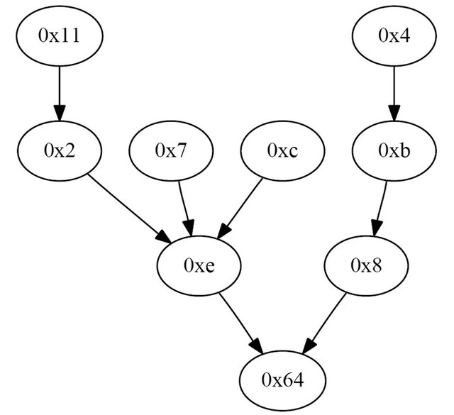
Figure 5. Network topology during the measurement. Each node has one or more routing paths to the base station node “0x64”. The solid line for a node represents the link to its parent node. Each node is 1, 2 or 3 hops from the base station node.
5.3.1. Comparing Measurement and Estimation for Transport Time Speed-Up
In order to confirm that our multihop incremental network programming improves programming time as predicted by the estimation, we compare the measurement for the transport time speed-up Stx-meas with the estimation Stx-est. Figure 6 compares the speed-up measurement Stx-meas with the estimation Stx-est for ChangeCon, AddLines and AddCom. For ChangeCon, the measurement of the transport time speed-up stays around 37.0 while the estimated speed-up is larger than 100. The reason why the measurement is much lower than the estimated value
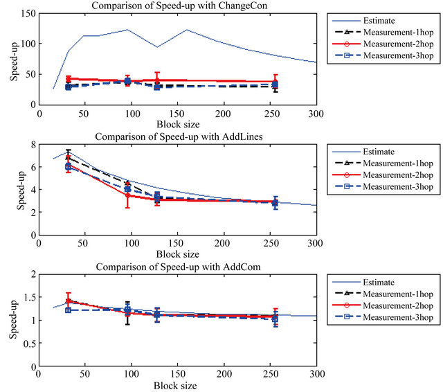
Figure 6. Speed-up of transport time for measurement results and estimation.
is that the estimation of transport time considered only the data size, which accounts for transmission delay. More realistic model of transmission time is the sum of transmission delay, propagation delay, queuing delay, and software overhead. For ChangeCon, the amount of transmission data gets smaller and the transport time becomes more dominated by the latency due to the link speed, retransmission and software overhead. Whereas for AddLines and AddCom, we can see that the measurement of the speed-up Stx-meas fits well to the estimation Stx-est. This is because the transport time speed-up is modest and the transport time is dominated by the data size.
5.3.2. Effect of Multihop Links
In order to see whether our incremental network programming scales well over multiple hops, we compare the measurement of the transport time Ttx-meas based on the hop counts. Figure 7 shows the trend of transport time over the hop counts for different combinations of test scenarios and patch block sizes. We can see that the tangent of each trend line gets smaller as hop count increases, which means that the transport time increases sub-linearly to the number of hops. Thus, we can say that our incremental network programming scales well under a multihop network.
5.3.3. Comparing the Total Programming Time
Up to now, we have considered only the transport time. To assess the effect on the total programming time, we can also consider the time for encoding and decoding stages. Figure 8 compares the speed-up for the total programming time Sall-meas with the speed-up for the transport time Stx-meas. For AddLines and ChangeCon, the overhead for the encoding and decoding stages is about the same scale as or is larger than the transport time, whereas the overhead is less than 20% for AddCom. Thus, the speed-up in total programming time for AddLines and ChangeCon becomes much smaller than the speed-up for the transport time:
• ChangeCon: Stx-meas = 37:0, Sall-meas = 9:4
• AddLines: Stx-meas = 6:3, Sall-meas = 4:1 While the overhead of the encoding and decoding stages is a limiter to the total programming time, it has room for improvement. First, the encoding program written in the Python programming language can be made faster by writing it in a more efficient programming language like C or C++. Second, the decoding program can be faster by writing a special version of the boot loader that can understand the patch. Currently, the decoding program generates a program image volume in the external flash and lets the boot loader copy the program image volume to the program image. Since the time
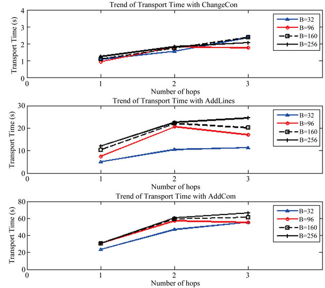
Figure 7. Trends of transport time over number of hops.
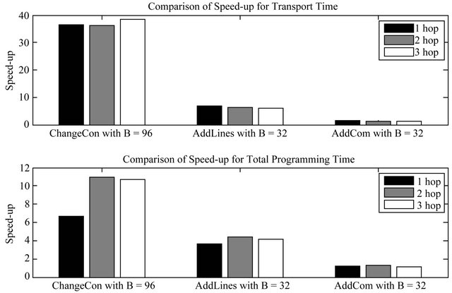
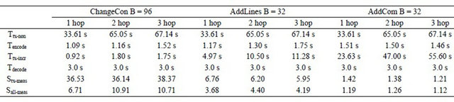
Figure 8. Speed-up for the transport and total programming time.
Table 4. Comparing the performance of our approach with other representative works.
for the decoding stage is dominated by the flash memory accesses, it can be faster by making the boot loader decode the patch and copy the patch blocks to the program memory without writing the intermediate program image volume to the external flash.
5.3.4. Comparison with Other Representative Works
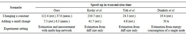
To confirm that our approach has a reasonable performance, we have compared the performance of our work with the reported performance results of other representative works for incremental network programming [12, 14,23]. To make a fair comparison, we have only considered the cases where the test scenarios are common: 1) changing of a constant and 2) adding a small change.
Table 4 shows that the performance of our approach is comparable to those of other approaches that require more intensive operations on the embedded nodes such as address indirection [12,14] and address patching [23]. A big difference is that the performance result of our work is demonstrated not only in estimation but also in measurement with multi-hop network. Whereas, the performance results of previous works were estimated either from the diff size [12,23] or from the energy consumption model on a single node [14].
6. Conclusion
Network programming is a method of re-tasking wireless sensor nodes by sending the program code over the network, and it enables updating the program code of sensor nodes without physically disrupting a sensor network deployment. In this paper, we further explored the problem space for network programming and identified requirements which emphasize flexible and speedy reprogramming. To achieve these goals, we designed our network programming component by composing several building blocks. For the basic network programming machinery, we used the image volume management module of Deluge2, copying the program image to the external flash memory and running the boot loader. For flexible network programming, we used the BLIP IPv6 stack to provide multihop IPv6 connectivity to the entire network of devices. For faster reprogramming, we updated the program image incrementally, generating the program image patch using the Rsync algorithm. With our wireless re-tasking method, we are able to get transport time speed-up factor of 37.0 for changing a constant and 6.3 for adding a few lines of code over non-incremental delivery. With the overhead of encoding and decoding considered, we are able to get total programming time speed-up factor of 9.4 for changing a constant and 4.1 for adding a few lines of code. Our wireless re-tasking method scales well with the programming time increasing sub-linearly to the diameter of the network.
REFERENCES
- C.-J. M. Liang and R. Musaloiu-E, “Deluge t2—Programming Manual,” 2008. http://www.tinyos.net/tinyos-2.x/doc/html/deluge-t2-manual.html
- S. Dawson-Haggerty, “Design, Implementation, and Evaluation of an Embedded ipv6 Stack,” M.S. Thesis, University of California, Berkeley, 2010.
- A. Tridgell, “Efficient Algorithms for Sorting and Synchronization,” Ph.D. Thesis, Australian National University, Canberra, 1999.
- Crossbow Technology, “Mote in Network Programming User Reference,” 2003. http://webs.cs.berkeley.edu/tos/tinyos-1.x/doc/Xnp.pdf
- T. Stathopoulos, J. Heidemann and D. Estrin, “A Remote Code Update Mechanism for Wireless Sensor Networks, Cens Technical Report #30,” 2003. http://lecs.cs.ucla.edu/~thanos/moap-TR.pdf
- J. W. Hui and D. Culler, “The Dynamic Behavior of a Data Dissemination Protocol for Network Programming at Scale,” ACM, New York, 2004.
- D. E. Culler and J. Hui, “Eecs-194 sp08, Lab 1—Embedded Internet,” 2008. http://www.cs.berkeley.edu/~culler/eecs194/labs/lab1/EECS194Lab01.html
- S. S. Kulkarni and L. Wang, “Multihop Network Reprogramming Service for Sensor Networks,” Proceedings of the 25th IEEE International Conference on Distributed Computing Systems, Columbus, 10 June 2005, pp. 7-16.
- P. Levis, N. Patel, S. Shenker and D. Culler, “Trickle: A Self-Regulating Algorithm for Code Propagation and Maintenance in Wireless Sensor Networks,” Proceedings of the First USENIX/ACM Symposium on Networked Systems Design and Implementation, San Francisco, March 2004, pp. 15-28.
- P. Levis and D. Culler, “Maté: A Tiny Virtual Machine for Sensor Networks,” Proceedings of the 10th Annual Conference on Architectural Support for Programming Languages and Operating Systems, Vol. 30, No. 5, 2002, pp. 85-95.
- J. Koshy and R. Pandey, “Vmstar: Synthesizing Scalable Runtime Environments for Sensor Networks,” Conference on Embedded Networked Sensor Systems, San Diego, 2-4 November 2005, pp. 243-254.
- J. Koshy and R. Pandey, “Remote Incremental Linking for Energy Efficient Reprogramming of Sensor Networks,” Proceedings of the 2nd European Workshop on Wireless Sensor Networks, Istanbul, 31 January-2 February 2005, pp. 354-365.
- N. Reijers and K. Langendoen, “Efficient Code Distribution in Wireless Sensor Networks,” Proceedings of the 2nd ACM International Conference on Wireless Sensor Networks and Applications, San Diego, 19 September 2003, pp. 60-67.
- A. Dunkels, N. Finne, J. Eriksson and T. Voigt, “RunTime Dynamic Linking for Reprogramming Wireless Sensor Networks,” ACM Press, New York, 2006, pp. 15-28.
- W. Dong, C. Chen, X. Liu, J. Bu and Y. Gao, “A Lightweight and Density-Aware Reprogramming Protocol for Wireless Sensor Networks,” IEEE Transactions on Mobile Computing, Vol. 10, No. 10, 2011, pp. 1403-1415.
- R. K. Panta and S. Bagchi, “Mitigating the Effects of Software Component Shifts for Incremental Reprogramming of Wireless Sensor Networks,” IEEE Transactions on Parallel and Distributed Systems, Vol. 23, No. 10, 2012, pp. 1882-1894. doi:10.1109/TPDS.2012.55
- P. J. Marron, M. Gauger, A. Lachenmann, D. Minder, O. Saukh and K. Rothermel, “Flexcup: A Flexible and Efficient Code Update Mechanism for Sensor Networks,” in EWSN ‘06, Feb 2006.
- K. Klues, C.-J. M. Liang, J. Paek, R. Musaloiu-E, P. Levis, A. Terzis and R. Govindan, “Tosthreads: ThreadSafe and Non-Invasive Preemption in Tinyos,” Proceedings of the 3rd European Workshop on Wireless Sensor Networks, Cork, 4-6 November 2009.
- A. Muthitacharoen, B. Chen and D. Maziéres, “A LowBandwidth Network File System,” SOSP’01 Proceedings of the 18th ACM symposium on Operating Systems principles, Vol. 35, No. 5, 2001, pp. 174-187.
- P. Deutsch, “Rfc 1950: Zlib Compressed Data Format Specification Version 3.3,” 1996. http://tools.ietf.org/html/rfc1950
- R. Rivest, “The md5 Message-Digest Algorithm,” 1992. http://tools.ietf.org/html/rfc1321
- J. Polastre, R. Szewczyk and D. Culler, “Telos: Enabling Ultra-Low Power Wireless Research,” 4th International Symposium on Information Processing in Sensor Networks, Los Angeles, 15 April 2005, pp. 364-369.
- T. Yeh, H. Yamamoto and T. Stathopolous, “Over-TheAir Reprogramming of Wireless Sensor Nodes, Ucla ee202a Project Report,” 2003. http://www.cs.ucla.edu/~tomyeh/ee202a/project/EE202a final writeup.doc
NOTES
*A portion of this paper is an amplification of Incremental Network Programming for Wireless Sensors; Jaein Jeong, and David Culler; First IEEE International Conference on Sensor and Ad Hoc Communications and Networks; Santa Clara, California; October 2004.