Journal of Water Resource and Protection
Vol. 2 No. 9 (2010) , Article ID: 2716 , 10 pages DOI:10.4236/jwarp.2010.29094
Development of Atmospheric Plasma Sprayed Dielectric Ceramic Coatings for High Efficiency Tubular Ozone Generators
1Institute for Manufacturing Technologies of Ceramic Components and Composites (IMTCCC), Universität Stuttgart, Stuttgart, Germany
2New Materials Technologies - TTI GmbH,Stuttgart, Germany
E-mail: miriam.floristan@gsame.uni-stuttgart.de
Received July 5, 2010; revised August 4, 2010; accepted August 15, 2010
Keywords: Ozone Production, Water Treatment, Thermal Spraying, Dielectric Strength, Permittivity
ABSTRACT
Oxidative degradation of hazardous materials by ozone treatment like in sterilization of water, dump waste, pulp bleach and chemical processing, is superior to the traditional chlorine chemistry with respect to by-products and environmental protection. For an efficient and cost effective production of ozone for applications in drinking water and wastewater purification, a new concept of tubular composite material components has been developed. A borosilicate glass tube was coated with a layer system consisting of an intermetallic electrode and a dielectric oxide ceramic surface layer. Thermo-mechanical and dielectric properties are investigated with respect to the use of different thermal spray powders as well as the use of a high and a low energetic atmospheric spray gun. The materials and ozone production system of thermal sprayed ozonizer tubes are described and analyzed.
1. Introduction
E Ozone is an environmentally benign chemical compound having the ability to replace commonly used chlorine compounds in many processes. It is one of the strongest oxidants surpassed only by fluorine in its oxidising power. Ozone is used as a germicide and bactericide for the treatment of potable and waste water as well as for bleaching processes and in further chemical oxidation steps. The use of the ozone as a primary oxidant before chlorination usually will satisfy most of the oxidant demand of the water being treated, thus lowering the subsequent demand for chlorine and minimizing the disinfection by products of chlorination, such as trihalomethanes (THMs) [1].
Ozonation has been used for tackling various industrial wastewaters [2-4]. However, its industrial applications have been handicapped by low ozone transfer efficiency and relatively high production costs [5]. The aim of the research project is the development of a novel powerful ozonizer tube, which cuts down the production costs and thus causes ozone to be an economically competitive alternative to traditionally used chlorine compounds [6-9].
In general, large quantities of ozone are generated by dielectric barrier discharges (DBD) [10-13]. Only these non-equilibrium gas discharges are suitable for an effective ozone generation. Since ozone is not chemically stable and decays during transportation, it is produced in a set of discharge tubes on site where it is needed in a tailored capacity.
The tube coatings are manufactured via Atmospheric Plasma Spraying (APS), a cost effective and very flexible manufacturing process. Various electrically insulating ceramic coatings (Al2O3, Al2O3-TiO2, ZrO2 with different stabilisers) are suitable as dielectric barrier material. In this paper, their phase composition as well as their thermomechanical and dielectric properties is studied and the suitability of the most promising coatings in the application is verified.
1.1. Principle of Ozone Generation
An ozonizer consists of two electrodes, which are separated by a gap and a dielectric (see Figure 1). Applying an alternating high voltage at the electrodes, leads to silent discharges within the gap. This results in partial ionization of the oxygen containing gas stream flowing through the discharge gap (air or pure oxygen) [8,9,14, 15].
The capacitors of most of the commercially available ozonizers are cylindrically shaped instead of plane-parallel. The dielectric prevents the controlled silent discharge to change into a glow or arc discharge that would damage or even destroy the ozonizer due to high currents. A silent discharge evenly distributed across the surface of the electrodes results in an optimum yield of ozone. If er of the dielectric is increased, higher field intensities within the discharge gap are possible, since the dielectric serves as a “protective resistor”. This leads to a higher efficiency of the ozonizer.
Ozone is generated within the discharge gap due to several chemical reactions of excited or dissociated oxygen species. Other gas species, which interact in form of three-body reactions, have also an influence on the efficiency of the process. Simultaneously, part of the generated ozone is lost again due to several decomposition processes [7,16,17].
The efficiency P of the ozonizer is in general proportional to the capacity C of the individual capacitor arrangement and the frequency f of the applied alternating voltage: P = k f C.
Thus, the efficiency of the ozonizer can be increased by operating the system either at a higher frequency or by increasing the capacity. Commercially available ozonizers are in general not equipped with a frequency converter and operate at a standard frequency range of 50-60 Hz.
1.2. Improved Ozonizer Tubes
Standard ozonizer tubes consist of a borosilicate glass tube with a thermally sprayed metallic coating applied to the inner surface of the tube. A special Atmospheric Plasma Spraying based coating technology was developed by EUROFLAMM in Bremen, Germany [8]. In this arrangement the tube itself serves as a dielectric. The metalized inner tube surface is electrically connected via metal brushes (see Figure 2). The borosilicate glass is restricted to a permittivity of er » 4.6. One possible way to improve the efficiency of the ozonizer arrangement is to introduce a dielectric material with a higher value for er. To keep the glass tube geometry, a straightforward way is to multicoat the glass tube with a metal layer serving as the inner electrode and a dielectric oxide [8]. The glass tube serves as a support, see Figure 3.
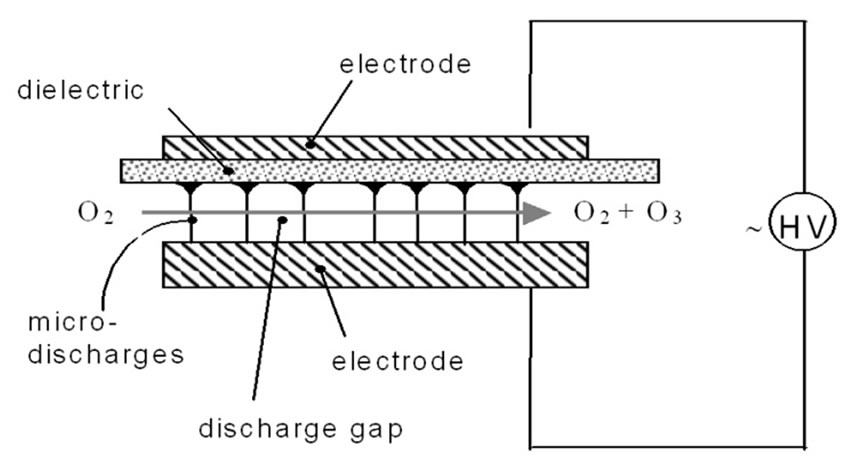
Figure 1. Schematic drawing of a capacitor arrangement for ozone production.
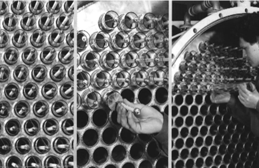
Figure 2. Commercial ozonizer with tube array.

Figure 3. Single glass tube with metal dielectric coating applied.
In the present study, results of metal dielectric multilayer structures based on aluminium alloys and several ceramic materials respectively are presented.
2. Methods
2.1. Principle of Atmospheric Plasma Spraying
Thermal spraying are a group of processes in which finely divided metallic and non-metallic materials are deposited in a molten or semi-molten state on a prepared substrate [18,19]. Atmospheric plasma spraying is a thermal spraying process in which the energy source to melt the spray material is an electric arc, which generates a plasma jet at atmospheric pressure. Due to the high temperatures achieved in the plasma heat source, over 8000 K [20], this is a very flexible coating technique able to process almost any material.
By means of a high voltage electrical discharge, an arc is created between a water-cooled copper cylindrical anode and a thoriated tungsten cathode situated inside the anode, see Figure 4(a). A gas mixture is injected in the torch and flows around the cathode and through the anode nozzle. The interaction of the electric arc with the gas mixture makes the gas atoms dissociate and ionize, leading to the formation of the plasma jet or plasma plume [18].
The powder is transported by a carrier gas and injected in the plasma. The particles are totally or partially melted by the plasma jet and propelled towards the substrate surface. Upon impacting at the surface, the particles deform and rapidly solidify forming splats. The coating is built up particle by particle. The coating structure is lamellar and inhomogeneous presenting oxidized particles, pores and unmelted or partially melted particles, see Figure 4(b) [21].
2.2. Selected Thermal Spray Powders and Substrate Material
The powders used in this work were commercially available powders as well as custom specified. All the materials used are chemically inert against ozone and oxygen radicals as well. The powders were characterised prior to spraying. Particle size distribution analysis was made with a Malvern Mastersizer by laseropthical method, particle morphology and phase composition were determined by SEM analysis and XRD respectively, see Table 1.
2.2.1. Metallic Electrode
In general, the metal electrode should present high electrical conductivity, high bonding strength to the borosilicate glass and oxidation resistance. With this aim, two materials were chosen; pure Al and Al/Si alloy. The alloy low thermal expansion coefficient, closer to the one of the borosilicate glass substrate, makes of this material an interesting option for the metallic electrode. However, the Si concentration in the alloy has to be over 50% in order to identify a significant change in the electrical conductivity of the material.
2.2.2. Dielectric Material
The thermal spray powders were selected attending to their appropriate thermophysical properties, reduced costs, coating process stability and commercial availability. Several oxide ceramics based on alumina, zirconia and titania alloys have been investigated. These materials showed high permittivity and are electrical insulators. Sintered TiO2 presents a permittivity ten times higher than that of Al2O3. However, during thermal spraying operations, TiO2 often undergoes a high reduction and rutile is then turned into non-stoichimetric TiO2 - x, changing therefore its physical properties. This modification can be considered as an n-type semiconductor with properties dependent on the extent of oxygen loss [22-24].
Several α-alumina powders and two types of stabilised zirconia powders with moderately high permittivities have been investigated and will be compared.
2.2.3. Substrate Material
The substrate material is a chemically inert borosilicate glass, which is commonly used as an ozonizer tube material. It is characterised by a very low thermal expansion coefficient of 3.3 10-6 K-1. This value is quite low compared with the CTE of most of the oxide ceramics that are applied on it. The thermophysical and dielectric properties of substrate and coatings are shown in Table 2.
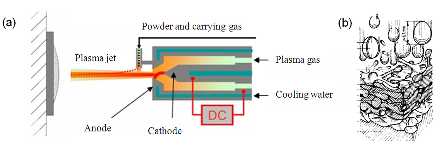
Figure 4. (a)Principle of atmospheric plasma spraying, (b)schematic draw of a plasma sprayed coating formation [21].
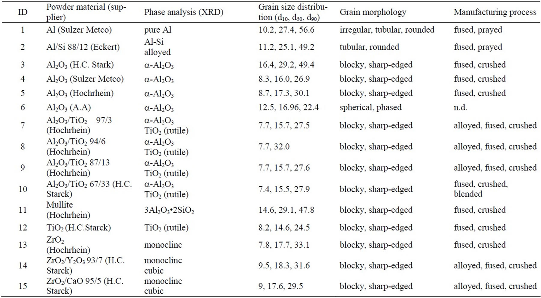
Table 1. Properties of the investigated powders.
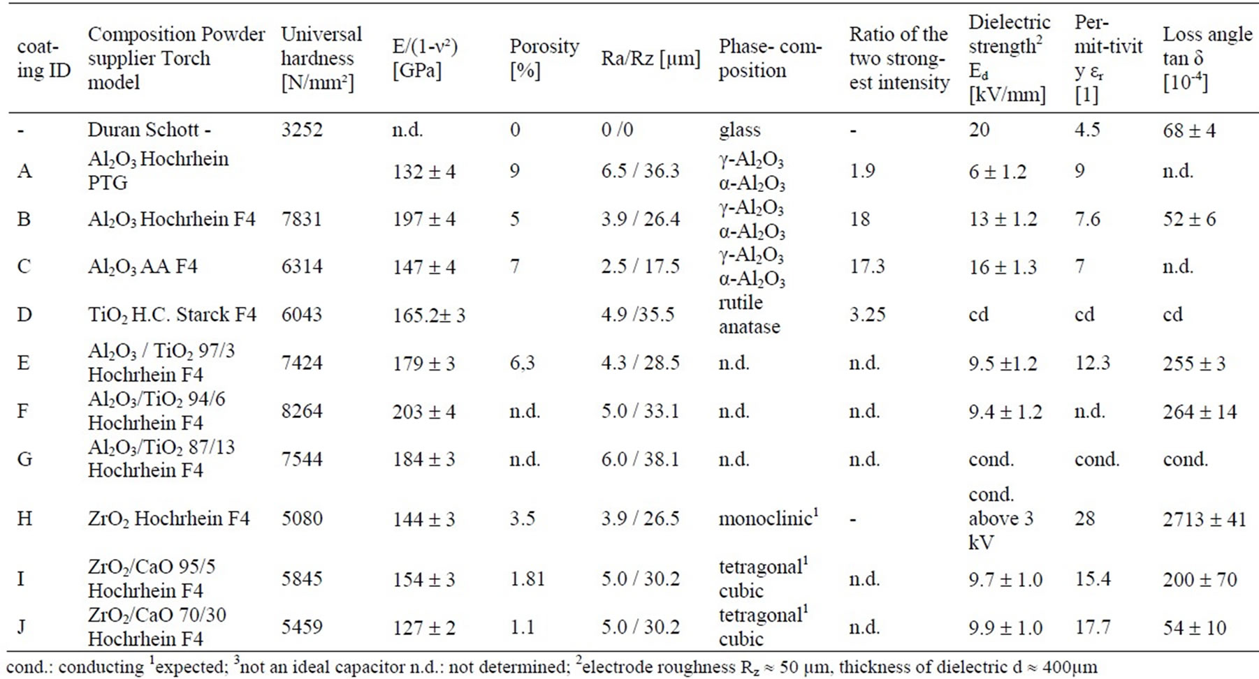
Table 2. Thermophysical and dielectric properties (ground electrode: Rz 50 µm) of the thermally sprayed coatings.
2.3. Experimental setup
2.3.1. Coating Deposition and Analytical Characterisation
All coatings have been deposited onto planar glass samples (100 × 100 × 2.5 mm³) via Atmospheric Plasma Spraying. Two different torches have been used. The first is a 80 kW Metco F4 torch and the second is a 15 kW PTG torch especially optimised to manufacture very fine grain sized powders. The torches were controlled by a fully programmable GTV MF-P-1200 unit. A procedure for optimising powder melting, deposition rate and sufficient adhesion to the substrate was carried out for each of the chosen powders. For TiO2, additional experiments have been carried out with a 4P and a TopGun®HVOF gun.
The coating characterisation and microstructure analysis was carried out by SEM and bright field optical microscopy [25,26]. Porosity has been determined from digital image processing of the respective cross section micrographs. Micro hardness of the thermal sprayed ceramic coatings was determined in the cross section in a Fisherscope H 100-V. The Young’s modulus was calculated from the elastic deformation energy during the dynamic hardness measurement. Another important aspect of this study was to evaluate the dielectric properties of the oxide ceramic coatings. Therefore the electrical permittivity εr and the loss angle tanδ were determined on planar samples via complex impedance spectroscopy and the dielectric strength Ed was measured using a 40 kV AC-analyzer, according to DIN VDE 0303 Part 21.
2.3.2. Ozone Production
Ozone production was carried out in a three tube ozone generator (Ozonia, LN103), which was modified to ensure convenient handling of the glass tubes. The ozonizer is equipped with sensors to record the oxygen gas flow, ozonizer current and voltage as well as the ozone concentration in the process gas, absolute pressure in the ozonizer, temperatures of the in and outlet gas and cooling water. Data recording was performed via personal computer. The parameters used for the ozone production evaluation are given below and were the same in all experiments carried out:
Process gas technical oxygen
Process gas flow vg = 0.19 m³/h
Process gas inlet temperature Tg,i = 20-25 ˚C
Vessel pressure pabs = 1600 mbar
Cooling water flow vw = 20 l/h
Cooling water inlet temperature Tw,i = 20-25˚C
3. Results and Discussion
According to the aim of this study, the investigated coating systems were analysed focusing on the application in ozonizers. Therefore a metallic electrode, an oxide ceramic and the dielectric properties of the metal-ceram ic-composite were analysed. Finally, the appropriate metal-ceramic-composites were tested in an ozonizer.
3.1. Deposition of the Metallic Electrode
The two metallic powders, Al and Al/Si alloy were deposited with low oxidation, and good adhesion to the substrate was obtained even though no shoot peening was performed. This indicates that the bonding mechanism is mainly of chemical nature, in comparison with the typically mechanical bonding mechanisms of thermal sprayed coatings. A higher deposition rate and adhesion was obtained in the Al/Si coatings. This could be explained attending to the lower CTE of the alloy compared with the pure Al, which may be closer to the value of the borosilicate glass. This can lead to reduced residual stresses and improved wettability behaviour due to the increased chemical compatibility between Al/Si and borosilicate glass.
Indeed, adhesion failure induced by residual stresses does not occur in the glass metal interface but within the glass substrate in a depth of about 20 microns. This behaviour indicates a strong physico-chemical bonding between the alloy and the borosilicate. However, further investigations have to be done to characterise the exact bonding mechanism.
During plasma spraying a defined heat transfer to the substrate or already deposited coating takes place, which is dependent on the spraying parameters, such as cooling rates, plasma gases, coating speed, etc. In some cases, the substrate to be coated is preheated prior to spraying in order to improve the coating adhesion. Figure 5 shows the cross section of two Al/Si 88/12 coatings processed with the same parameters except for the substrate pre heating, which was applied only on one of them. Both coatings have good contact to the glass. It can be seen, that although Al/Si 88/12 is an eutectic material, two phases are formed in the coating; a Si-phase and an Al-dendrites. The formation, distribution and growth of the Si-phase is strongly dependent of the temperature curves during the spraying process. Due to the different microstructure, different conductance values are achieved. However all coatings have a sufficient high electrical conductance for the application.
3.2. Oxide Ceramic Coatings
All oxide coatings have been deposited onto the glass-metal multilayer substrate. The thermophysical properties of all sprayed oxide coatings are listed in Table 2.
3.2.1. Al2O3 Coating
Pure α-Al2O3 of several suppliers have been plasma sprayed (see Figure 6(a) and Table 2). During plasmaspray process, some α-Al2O3 is transformed into γ-Al2O3, and the main phase found in the thermally sprayed coating is the cubic γ-Al2O3. This effect has been extensively discussed in the literature and was explained by McPherson attending to nucleation kinetics [27]. Due to its lower interfacial energy between crystal and liquid, γ-Al2O3 is more easily nucleated from the melt than α-Al2O3, being therefore the metastable phase, if cooled rapidily enough, the one retained to ambient temperature and therefore present in the coating [27]. The cooling rate of APS processes, which can be in the range of 106 K/s [28], strongly determines the phase composition of the coating. Generally, the higher the cooling rate, the more the γ phase [29,30]. The presence of α-Al2O3 on the coating indicates the uncompleted melting of some of the particles during coating [31] and depends thus on the process parameters [32]. Usually the stable α-Al2O3 is, due to its superior chemical and mechanical properties, desired in the coatings. The change of the γ-phase to the stable α -phase induces a significant volume change (γ to α: volume change of ~15%) which can result in micro crack formation and related problems.
The intensity ratios of the α and γ XRD peaks of the various plasma sprayed alumina coatings are given in Table 2. All ratios having values about 17 or 18 except the with PTG torch sprayed alumina “A” that has a value of 1.9. This corresponds to a very high amount of α-alumina and is probably due to a high concentration of unmolten particles in the coating resulting of the coarse milled powder. Comparing the XRD-ratios of coating “B”, which was sprayed using the same powder but the higher energetic F4-torch, confirms this assumption; the PTG torch does not seem to be able to fully melt the reasonable high fraction of alumina powder particles with grain sizes above 20µm and therefore, the cross section shows high inhomogenities in the microstructure, unmolten particles, high porosity and as follows, the coating has a low dielectric strength. Further experiments show that with the use of finer grinded powders, homogeneous very fine structured coatings can be achieved with the low energetic PTG torch.
Especially for the use in dielectric applications, a low porosity is desired to achieve high dielectric strength of the dielectric layer. Lowest porosities have been obtained with the spherolytic alumina powder, coating “C” Table 2. The used powder has a very narrow grain size distribution of – 22 + 15 µm, so that the plasma is able to fully melt nearly all powder particles. Moreover, a very stable spraying process can be obtained due to the high flowability of the spherical shaped powder grains and a very high coating quality was achieved.
3.2.2. TiO2 Coatings
Stoichiometric TiO2 powder was deposited by atmospheric plasma spraying. The reduction of this oxide could not be avoided during the plasma spraying process and the material loses its electrical insulating character (coating “D”, Table 2).
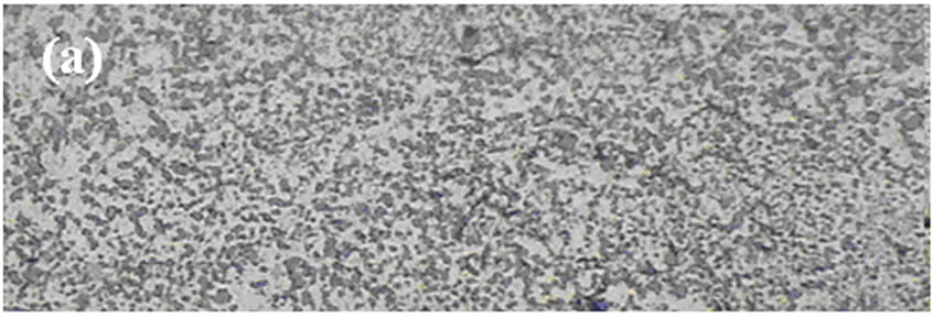
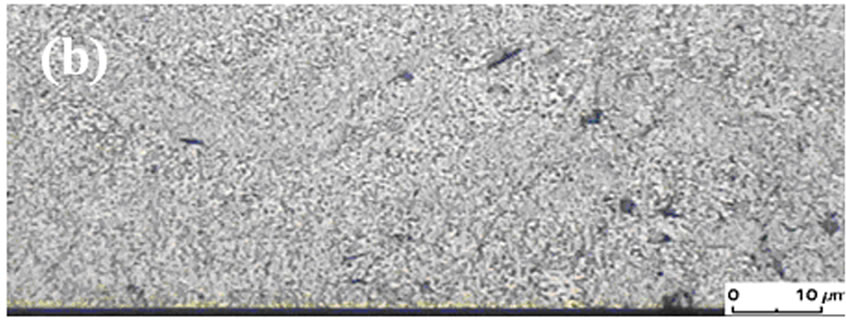
Figure 5. Cross section of an Al/Si 88/12 coating with (a) and without (b) preheating the substrate.
Several experiments have been done to deposit TiO2 by flame spraying with the “4P” Metco and the TopGunÒ HVOF gun in an oxygen enriched flame (small λ) and simultaneous oxygen cooling gas jet to force the deposition of oxygen stoichiometric TiO2 coatings. The results were the same as in the APS experiments; TiO2 could only be deposited in oxygen understoichiometric modification.
3.2.3. Al2O3/TiO2 Coatings
Several Al2O3/TiO2 oxide powders with different content of TiO2 were plasma sprayed (coatings “E” to “G”, Table 2). The higher amount of TiO2 in the powders leads to higher coating permittivity values but it gives place also to a decrease in the coating insulating properties, since substoichiometric phases appear in the system. The plasma sprayed coatings exhibit separate phases of Al2O3 and understoichiometric TiO2 as can be seen in micrographs. No forming of tialite (Al2TiO5) has been observed, as could be expected from some studies presented in the literature [33].
Coating “F” (Table 2) Al2O3/TiO2 94/6 shows the highest permittivity within the alumina based coatings, but the dielectric behaviour is not that of an ideal capacitor, the permittivity strongly depends on the testing frequency. For concentrations above 6 wt% of TiO2, no electrical insulating APS coating can be achieved (coating “G”, Table 2).
3.2.4. ZrO2 Coatings
Due to its high melting temperature, pure zirconia, as well as partially and fully calcia stabilised zirconia, were deposited with the high power F4 torch (coatings “H”, “I”, “J”, Table 2). The deposition efficiency of the coating process was about 70%. In Figure 6(b), a typical cross section of a zirconia coating is shown, there is an excellent bonding between glass‑Al/Si and Al/Si‑zirconia. The ceramic shows a low porosity and high homogeneity. The zirconia based coatings have reached the highest permittivity values and a dielectric strength of about 10 kV/mm.
Like TiO2, pure ZrO2 undergoes a structure transformation and becomes conducting during the spraying process. Electrical conductivity starts at voltages above 3 kV. This could be due to vacancies in the crystal lattice comparable to the TiO2-system or due to impurities. Subsequently and although this material presents permittivity values two or three times higher than all the other analysed materials, it is not appropriate for the use in ozonizer tubes.
On the other hand the calcia stabilised zirconia does not show conducting or semi‑conducting properties (coatings “I”, “J”, Table 2). The coatings are electrical insulators even at high voltages. The fully stabilised zirconia (coating “J”, Table 2) has a lower Young’s modulus, a higher permittivity and a smaller loss angle than the partially stabilised ZrO2. Therefore it is expected, that this coating presents lower residual stress, higher capacity and lower Ohmic loss. In comparison with all the investigated coatings, it is the most promising one for the application of study.
3.3. Dielectric Properties
The measured dielectric strengths and permittivities of the analysed sprayed coatings are listed in Table 2. As discussed previously, the use of titania and pure zirconia coatings as dielectrics is not appropriate due to their increased electrical conductivity after being thermally sprayed.
The dielectric strength is the voltage necessary to induce an electric breakdown in an electrical insulating material of 1 mm thickness. During electric breakdown, the material is locally molten and a pinhole is formed. As will be discussed, the dielectric strength of thermally sprayed coatings is also determined by several mechanical properties like the coating roughness of the metallic interface, as well as the porosity and the thickness of the ceramic top layer.
3.3.1. Influence of the Metal Interface Roughness
After spraying the metal interface, the surface roughness of the sprayed metal electrode was modified by polishing or by using a finer grain size distribution of the spray powder (–20 + 35 µm). The ceramic layer thickness was about 300 µm. The data shows clearly that the breakthrough voltage depends strongly on the interface roughness (Figure 7(a)). The voltage breakthrough is due to strong local electric field inhomogenities caused by discrete peaks sticking out of the metallic interface. Smoothing the surface circumvent strong field inhomogenities and as a result, higher voltages are necessary to create an electrical breakthrough.
Because ozonizer tubes need a high dielectric strength, a minimised electrode surface roughness is desired. On the other hand, the adhesion of the thermal sprayed ceramic layer to the metal electrode is mainly of mechanical nature and increases with higher roughness. Experiments have pointed out, that the electrode roughness should not be under Rz = 20 µm in order to prevent delamination of the ceramic layer.
3.3.2. Influence of the Oxide Layer Thickness
The maximum reachable coating thickness is limited due to an increase of internal stresses that finally can lead to delamination of the coating or even to destruction of the glass substrate. This is caused by the thermophysical incompatibilities of the ceramic, metal and glass materials, such as their very different coefficients of thermal expansion: αglass = 3.3 × 10⁻⁶/K, αAl = 14 × 10‑6/K, αceramic = 8 × 10⁻⁶/K. The maximum reachable coating thicknesses are in the range from 400 µm to 600 µm for planar substrates.
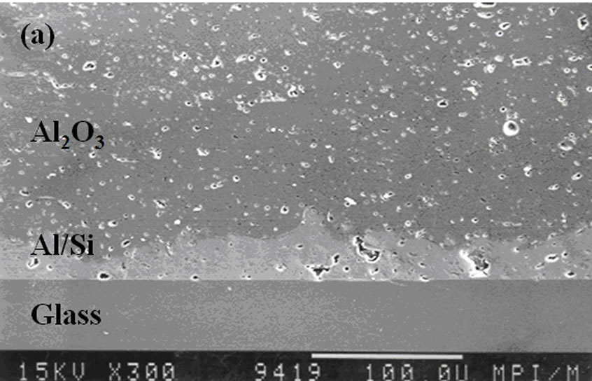
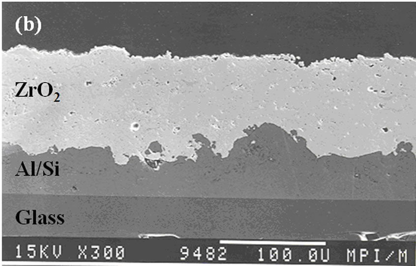
Figure 6. (a)Cross section SEM of APS Al2O3 coating and (b)of APS zirconia coating.
Figure 7(b) illustrates the breakdown voltage as a function of the coating thickness of the oxide alumina layer. The dielectric strength is more or less constant until thicknesses of around 400 µm and tends to decrease for higher values. A possible explanation for this behaviour is the increase of micro-cracks induced by internal stresses. This effect has already been observed in literature [30,34]. However, this is one of the main problems faced when dealing with thermal sprayed coatings.
3.4. Upscaling and Ozone Production
In order to be able to use ozone tubes in the ozone generator, it is necessary that the breakdown voltage of coated tubes reaches at least 13 kV. As the experiments show, thermal sprayed dielectric coatings with a thickness of 1000 µm and above can sustain such high voltages. The deposition of 1000 - 1300 µm thick dielectric coatings on metalized glass tubes caused several problems. As discussed in the last section, the high internal stresses in the coating system can lead to complete destruction of the glass tubes (Figure 8).
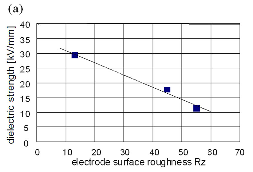
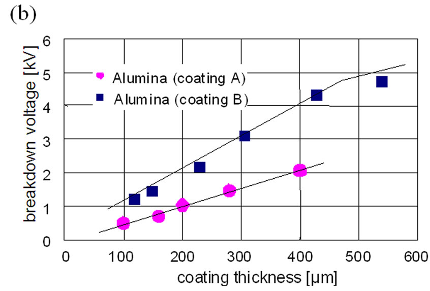
Figure 7. (a)Dielectric strength of Al/Si metal alloy and Al2O3 multilayer coatings (coating B, 300 µm) as a function of surface roughness, and (b)breakdown voltage in dependency of the coating thickness for two types of thermal sprayed Al2O3 ceramic coatings.
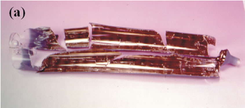
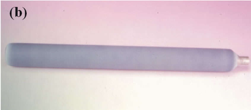
Figure 8. (a)Destructed and (b)non-destructed coated glass tube (Al/Si and Al2O3/TiO2) due to different residual stress situation.
The internal stress of multicoated metal-ceramic borosilicate glass was determined by 3D-deformation, drill hole measurement and numerical stress analysis (FEM). Because of these experiments, it was concluded that a successful coating process of glass tubes implies an optimisation of the plasma parameters, the use of sophisticated simultaneous cooling techniques and a stress optimised geometry of the glass tubes.
The glass tubes were coated with 50 µm Al/Si 88/12 and approximately 1000 µm ceramic coating. Presently two different dielectrics were tested, Al2O3/TiO2 97/3 (coating “E”) and ZrO2/CaO 70/30 (coating “J”).
Figure 9(a) shows the current-voltage curves of the ozonizer with glass and plasma sprayed tubes. The characteristic curves of the two novel tubes are similar, but differ from the behaviour of the traditional glass tubes. All curves show two clearly distinguishable regions with different slopes (named region I and region II in Figure 9(a)). In region I no dielectric barrier discharges occur. The capacitor is only charged and discharged, and therefore the current is very small and nearly independent of the voltage. In region II the electrical field in the gap overcomes the Paschen´sche field, DBD appear and ozone is produced.
The lower slopes of the curves for the coated tubes in region II indicate that the Ohmic resistance, and therefore the Ohmic loss, has a lower value. As can be observed in Figure 9(a) the voltage necessary for the formation of DBD, and therefore the beginning of ozone production, is approximately 3 kV lower in the case of coated tubes. It should be noted that the maximum efficiency value for ozone production is also reached at lower voltage values.
In Figure 9(b) the ozonizer production efficiency of traditional and novel ozonizer tubes are compared. With the novel ozonizer tubes, an increase of the ozone production efficiency up to 30% is observed (15% with Al2O3/TiO2 94/6 and 30% with ZrO2/CaO 70/30). The decrease of the ozone production efficiency at higher power supply of the ozonizer is due to the partial decomposition of the higher ozone concentration in the used gas.
The ozone production efficiency is correlated to the permittivity. Nevertheless, the often made assumption that the ozone production efficiency is proportional to the capacity of the ozonizer tube is not correct, otherwise the ozone production would increase to at least 200% to 300% with the use of the novel tubes.
There is strong evidence that the ozone production efficiency is a complex function of a series of parameters, i.e. the electron work function of the ceramic material, the surface roughness of the electrode and the dielectric, the gap spacing, the power supply characteristics etc.
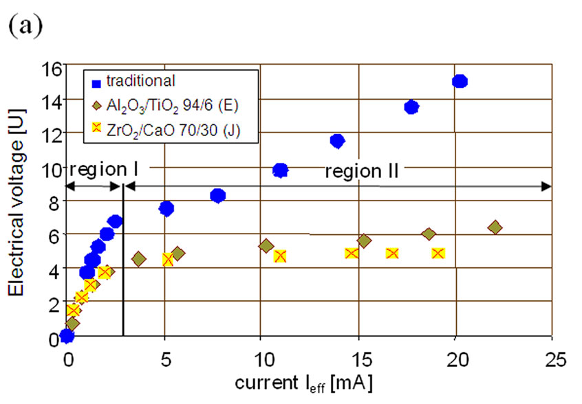
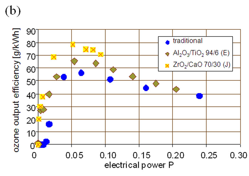
Figure 9. (a)Current-voltage curve for traditional and two novel plasma sprayed ozonizer tubes, and (b)ozone production efficiency versus electrical power for traditional and two novel plasma sprayed ozonizer tubes.
4. Conclusions
In this work, the deposition of thermally sprayed metal-ceramic bilayer coatings on borosilicate glass tubes to be used in the production of ozone has been investigated. The coatings consist of an Al/Si intermetallic interlayer representing one of the electrodes, and an oxide ceramic top coating on the glass acting as a dielectric.
Coating experiments on borosilicate glass of the metal layer and different oxide ceramics like Al2O3, ZrO2 and TiO2 have been carried out. Improved permittivities, with values three times higher than in traditional ozonizer tubes, were obtained. The coating microstructure in terms of porosity, thickness and micro-cracking of the oxide layer and surface roughness of the metallic electrode greatly influence the dielectric strength of the composite. The dielectric breakthrough of the system was successfully increased by the deposition of residual stress optimised 1000 µm ceramic coating.
First results using the new type of thermally coated ozonizer tubes in a laboratory ozonizer already performed an approximately 30% higher efficiency compared to conventional glass tubes.
REFERENCES
- M. A. T. Alsheyaba and A. H. Muñoz, “Optimisation of Ozone Production for Water and Wastewater Treatment,” Desalination, Vol. 217, No. 1, 2007, pp. 1-7.
- F. L. Evans, “Ozone Technology: Current Status,” In: F. L. Evans, Ed., Ozone in Water and Wastewater Treatment, Ann Arbor: Ann Arbor Science Publishers Inc., MI, USA, 1972, pp. 1-13.
- R. G. Rice and M. E. Browning, “Ozone Treatment of Industrial Wastewater,” Noyes Data Corporation, Park Ridge, New York, USA, 1981.
- S. H. Lin and K. L. Yeh, “Looking to Treat Wastewater? Try Ozone,” Chemical Engineering, Vol. 100, No. 5, 1993, pp. 112-116.
- S. H. Lin and C. H. Wang, “Industrial Wastewater Treatment in a New Gas-Induced Ozone Reactor,” Journal of Hazardous Materials, Vol. 98, No. 1-3, 2003, pp. 295-309.
- F. Gaia and A. Menth,“Neue Hochleistungs-Ozonerzeu ger und ihr Anwendungspotential,” Proceedings 5. OzonWeltkongreß, Berlin, 1981, pp. 325-339.
- U. Kogelschatz and B. Eliasson, “Die Renaissance Der Stillen Elektrischen Entladung,” Physikalische Blätter, Vol. 52, No. 4, 1996, pp. 360-362.
- R. Gadow and G. Riege, “Ozoniser and Method of Manufacturing it,” European patent, EP 0 817 756 B1, 1996.
- M. Hirth, “Ozonizer,” European patent, EP 0 202 501 B1, 1986.
- M. Labrenz, “Elektrische Gasentladung zur Ozonherstellung,” Ph. D. dissertation, University Aaachen, 1983.
- P. Braumann, “Über die Erzeugung von Gasentladungen zur Herstellung von Ozon,” Ph. D. dissertation, University Aachen, 1981.
- J. Lemmerich, “Die Entdeckung des Ozons und die ersten 100 Jahre Ozonforschung,” Sigma Verlag, Berlin, 1990.
- U. Kogelschatz, “Advanced Ozone Generation,” In: S. Stucki, Ed., Process Technologies for Water Treatment, Plenum Press, New York, 1988, pp. 87-120.
- U. Kogelschatz, “Apparatus for producing Ozone,” Europeran patent, EP 0 019 307 A1, 1980.
- M. Fischer and H. Lang, “ Vorrichtung zur Erzeugung von Ozon,” German patent, DE 41 07 072 A1, 1991.
- B. Eliasson and U. Kogelschatz, “Modelling and Applications of Silent Discharge Plasmas,” IEEE Transactions on Plasma Science, Vol. 19, No. 2, 1991, pp. 309-323.
- B. Elvers and S. Hawkins, “Ullmann´s Encyclopedia of Industrial Chemistry A18,” VCH Verlag, Weinheim, 1991.
- L. Pawlowski, “The Science and Engineering of Thermal Spray Coatings,” 2nd Edition, John Wiley & Sons Ltd, Chichester, 2008.
- P. Fauchais, “Understanding Plasma Spraying,” Journal of Physics D: Applied Physics, Vol. 37, No. 9, April 2004, pp. 86-108.
- P. Fauchais, “Understanding Plasma Spraying,” Journal of Physics D: Applied Physics, Vol. 37, 2004, pp. 86-108.
- R. B. Heimann, “Plasma Spray Coating,” 2nd Edition, WileyVCH Verlag GmbH & Co. KGaA, Weinheim, 2008.
- A. Ohmori, K.C. Park, M. Inuzuka, Y. Arata, K. Inoue, and N. Iwamoto, “Electrical Conductivity of Plasma-Sprayed Titanium Oxide (rutile) Coatings,” Thin Solid Films, Vol. 201, No. 1, 1991, pp. 1-8.
- P. Kofstad, Nonstoichiometry, “Diffusion and Electrical Conductivity in Binary Metal Oxides,” Wiley-Interscience, New York, 1972.
- T. Bak, J. Nowotny and C. C. Sorrel, “Electrical Properties of Metal Oxides at Elevated Temperatures,” Key Engineering Materials, Vol. 125-126, No. 1, 1997, pp. 1-80.
- H. Du, J. H. Shin and S. W. Lee, “Study on Porosity of Plasma-Sprayed Coatings by Digital Image Analysis Method,” Journal of Thermal Spray Technologies, Vol. 14, No. 4, 2005, pp. 453-461.
- S. D. Glancy, “Preserving the Microstructure of Thermal Spray Coatings,” Advanced Materials & Processes, Vol. 7, No. 1, 1995, pp. 37-40.
- R. McPherson, “Formation of Metastable Phases in Flame and Plasma-Preapared Alumina,” Journal of Material Sciences, Vol. 8, No. 6, 1973, pp. 851-858.
- L. Zhao, K. Seemann, A. Fischer and E. Lugscheider, “Study on Atmospheric Plasma Spraying of Al2O3 Using On-Line Particle Monitoring,” Surface and Coating Technologies, Vol. 168, No. 2-3, 2003, pp. 186-190.
- P. Chráska, J. Dubsky, K. Neufuss and J. Píacka, “Alumina-Base Plasma-Sprayed Materials Part I: Phase Stability of Alumina and Alumina-Chromia,” Journal of Thermal Spray Technology, Vol. 6, No. 3, 1997, pp. 320- 325.
- L. Pawlowsky, “The Relationship Between Structure and Dielectric Properties in Plasma-Sprayed Alumina Coatings,” Surface and Coating Technologies, Vol. 35, No. 3-4, 1988, pp. 285-298.
- S. Yilmaz, “An Evaluation of Plasma-Sprayed Coatings Based on Al2O3 and Al2O3 13 wt% Tio2 with Bond Coat on Pure Titanium Substrate,” Ceramics International, Vol. 35, No. 5, 2009, pp. 2017-2022.
- R. McPherson, “On the Formation of Thermally Sprayed Alumina Coatings,” Journal of Material Sciences, Vol. 15, No. 12, 1980, pp. 3141-3149.
- R. Yilmaz, A. O. Kurt, A. Demir and Z. Tatli, “Effects of Tio2 on the Mechanical Properties of the Al2O3-Tio2 Plasma Sprayed Coating,” Journal of European Ceramic Society, Vol. 27, No. 2-3, 2007, pp. 1319-1323.
- L. Golonka and L. Pawlowski, “Ceramic on Metal Substrates Produced by Plasma Spraying for Thick Film Technology,” Electrocomponent Science and Technology, Vol. 10, No. 2-3, 1983, pp. 143-150.