Journal of Biomedical Science and Engineering
Vol.7 No.4(2014), Article ID:43707,14 pages DOI:10.4236/jbise.2014.74023
Pulsatile MHD Flow in an Inclined Catheterized Stenosed Artery with Slip on the Wall
Mukesh Kumar Sharma, Kuldip Singh, Seema Bansal
Department of Mathematics, Guru Jambheshwar University of Science & Technology, Hisar, India
Email: drms123@gmail.com
Copyright © 2014 by authors and Scientific Research Publishing Inc.
This work is licensed under the Creative Commons Attribution International License (CC BY).
http://creativecommons.org/licenses/by/4.0/


Received 22 January 2014; revised 28 February 2014; accepted 8 March 2014
ABSTRACT
Catheter is commonly used by the surgeons for various reasons in the treatment of a patient suffering with cardiovascular diseases. Catheterization increases the mean flow resistance in the arterial blood flow and many other complications are associated with the presence of catheter in the artery. Effects of catheter in stenosed artery can be estimated non-invasively by means of hemodynamic indicator-WSS, WSSG, volume flow rate and impedance. The effect of slip at the arterial wall, inclination of the artery and magnetic field on the hemodynamic indicators and flow profiles are computed, presented and discussed through graphs.
Keywords:Stenosed Artery; Wall Shear Stress; Wall Shear Stress Gradient; Impedance; Catheter

1. Introduction
A significant change in blood flow, pressure distribution, wall shear stress and resistance to flow has universally observed when an impediment has developed in the arterial lumen. Generally, in the artery, the impediment developments are resulted from the lipoproteins and fatty acids deposition at the sites of atherosclerosis lesion. Consequently, a stenosed artery has been formed. In the stenosed section the velocity gradient near the wall region is steeper due to the increased core velocity resulting in relatively large shear stress on the wall even for a mild stenosis. Several researchers Fung [1] , McDonald [2] , Mazumdar [3] and Zamir [4] have given mathematical treatment to the blood flow in arteries subject to various physiological conditions. A fairly good number of theoretical and experimental studies on the blood flow through stenosed artery are available in the published literature, and some of them are Young [5] , Srivastava [6] [7] , Liu et al. [8] , Yao and Li [9] , Mekheimer and ElKot [10] .
The use of catheters is of immense importance and has become a standard tool for diagnosis and treatment in modern medicine. When a catheter is inserted into the stenosed artery, the further increased impedance or frictional resistance to flow will alter the velocity distribution. Kanai et al. [11] established analytically that for each experiment, a catheter of an appropriate size is required in order to reduce the error due to the wave reflection at the tip of the catheter. The mean flow resistance increase during coronary artery catheterization in normal as well as stenosed arteries has been studied by Back et al. [12] . A number of theoretical studies of suspensions in general and blood flow in particular are given by Jones [13] , Nuber [14] , Brunn [15] , and experimental studies by Bugliarello and Hayden [16] ; Bennet [17] , suggest the likely presence of slip (a velocity discontinuity) at the flow boundaries (or in their immediate neighbourhood). Misra and Shit [18] , Ponalgusamy [19] , have developed mathematical models for blood flow through stenosed arterial segment, by taking a velocity slip condition at the constricted wall.
The study of flow of an electrically conducting fluid through a stenosed artery with permeable walls not only possesses a theoretical importance, but also is useful for many biological and engineering problems such as magnetohydrodynamics (MHD) generators, blood flow problems, plasma studies. In the technical fields, the specification of MHD studies can be found in Moreau [20] . Kolin [21] has established that the biological systems in general are greatly affected by the application of external magnetic field. Barnothy [22] investigated that the heart rate decreases by exposing biological systems to an external magnetic field. Korchevskii and Marcochnik [23] have discussed the possibility of regulating the blood movement in human system by applying magnetic field. In the decade of eighties, engineers attracted towards impact of magnetic field in biomedical flow primarily with a view to utilizing MHD (magnetohydrodynamics) in controlling blood flow velocities in surgical procedures and also establishing the effects of magnetic fields on blood flows in astronauts, citizens living in the vicinity of EM (electromagnetic) towers etc. Several researchers [24] -[26] have worked out significant studies on hydromagnetic blood flow in artery. Layek et al. [27] and Kumar et al. [28] worked on a mathematical model to study flow through a variable shape stenosed artery under the influence of magnetic field and demonstrated the effect of stenosis shape and magnetic field on the resistance to the flow. Mekheimer [29] studied MHD, viscous, incompressible fluid flow in an inclined plane channel with electrical insulated walls using a perturbation expansion. They found the explicit relation for velocity flow, pressure rise and flow rate in terms of Reynolds number, wave number, Hartmann number, fround number, inclined angle and the occlusion.
These researches motivated for the present study of blood flow in catheterized stenosed artery subject to a velocity slip at the stenosed arterial wall under the influence of transverse magnetic field will be quite rational for theoretical study of blood flow and explanation of disease linked with flow dysfunction.
2. Formulation of the Problem
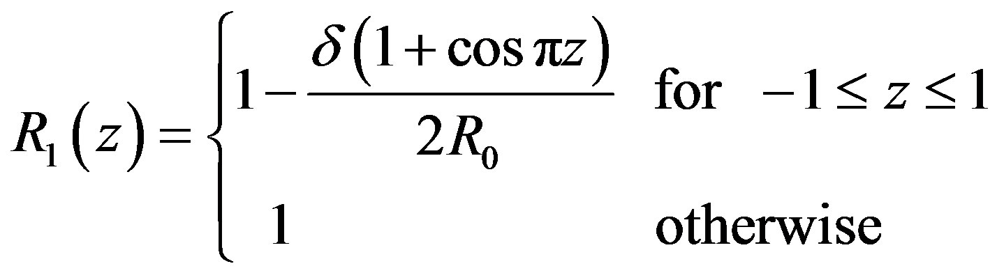
The problem considered here is to study pulsatile blood flow through an inclined axially symmetric catheterized stenosed artery with slip velocity at the arterial wall. The blood vessel geometry is determined by the radius R0 of the inlet and outlet unconstricted segment, whereas the radius of the smooth axisymmetric constricted segment is given by
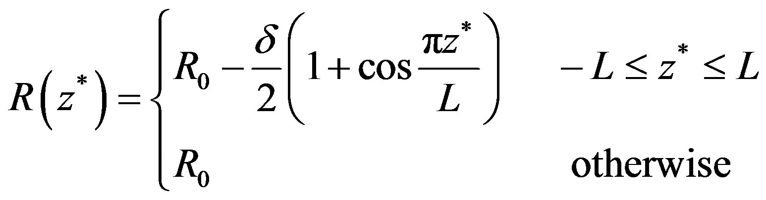 (1)
(1)
where 2L is the length of stenosis and δ is maximum height of the stenosis.
In the cylindrical coordinate system , the axis of the vessel coincides with the
  -axis and the origin
  corresponds to the peak point of the stenosis. The diameter of the artery is assumed to be greater than 1 mm so that Fahreus-Lindquist effect is not significant. The flow through the artery is in the influence of external magnetic field, an electromagnetic force will be produced due to the interaction of current with magnetic field when electrically conducting fluid like blood is flowing in the magnetic field.
The electromotive force is proportional to the speed of motion and the magnetic flux intensity B (Tashtoush and Magableh, [30] ). The Maxwells equations describing the magnetohydrodynamic flow are
 (2)
(2)
 (3)
(3)
 (4)
(4)
where,  is the electric field intensity,
  is the magnetic flux intensity
  is the electric permeability and
  is the current density. If
  is the electrical conductivity, Then generalized Ohm’s law is
 (5)
(5)
The induced electromagnetic force  is defined as
 (6)
(6)
Following Cowling [31] that there is no applied or polarization voltage so that . We assumed a magnetic field
  with a constant transverse magnetic flux density
  of moderate strength so that induced magnetic field is negligible. On the flowing blood with velocity field in the cylindrical coordinate system described by
  the magnetohydrodynamic force is
 (7)
(7)
 the unit vector in axial direction. Invoking these assumptions the governing equations of the motion of blood as Newtonian incompressible fluid with axisymmetric condition is given by
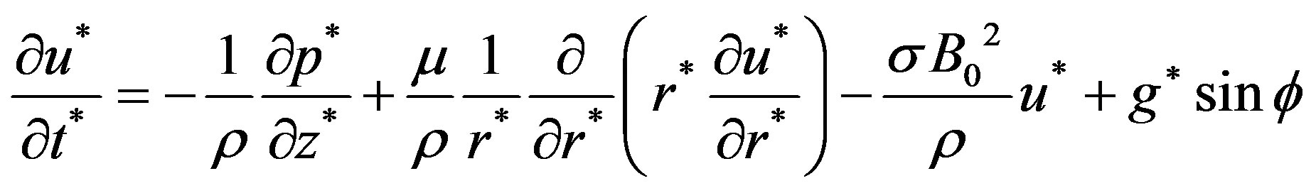 (8)
(8)
 (9)
(9)
where,  axial velocity,
  the pressure,
  time,
time,  viscosity of the blood, ρ density of the blood,
  gravitational acceleration,
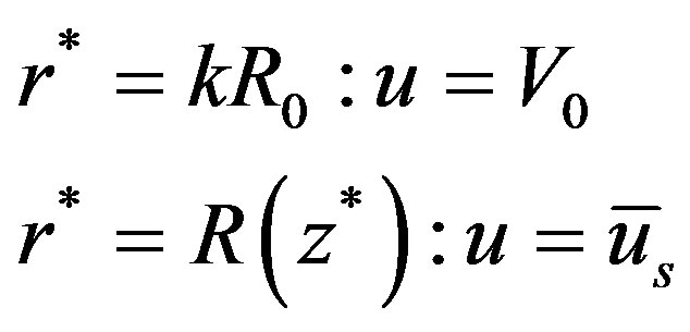
  the aspect ratio of catheter radius to radius of artery,
  catheter speed,
  the slip velocity,
  inclination of the artery as shown in Figure 1.
3. Mathematical Analysis
Introducing the following non-dimensional parameters:
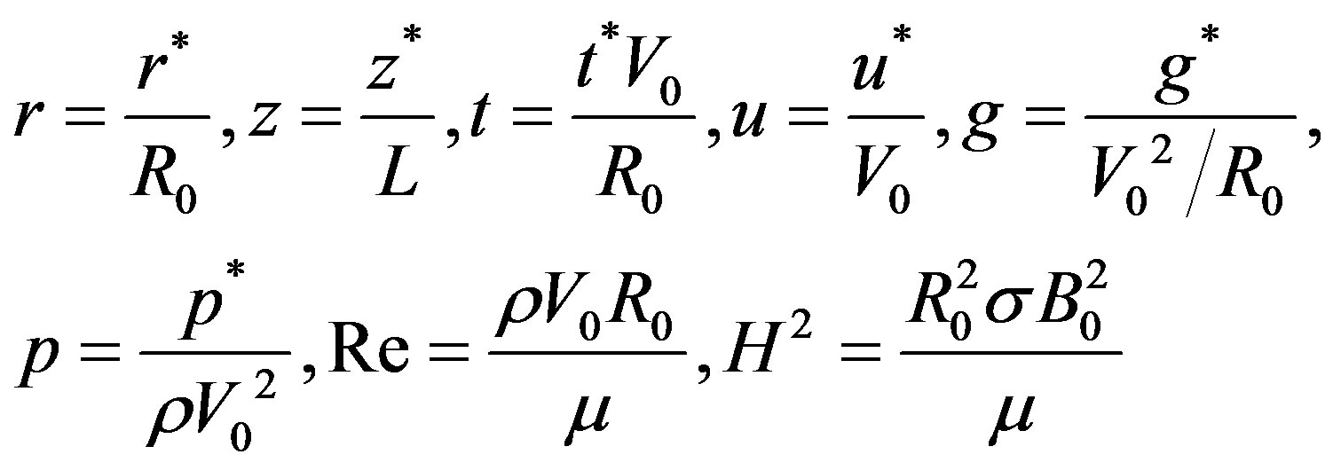 (10)
(10)
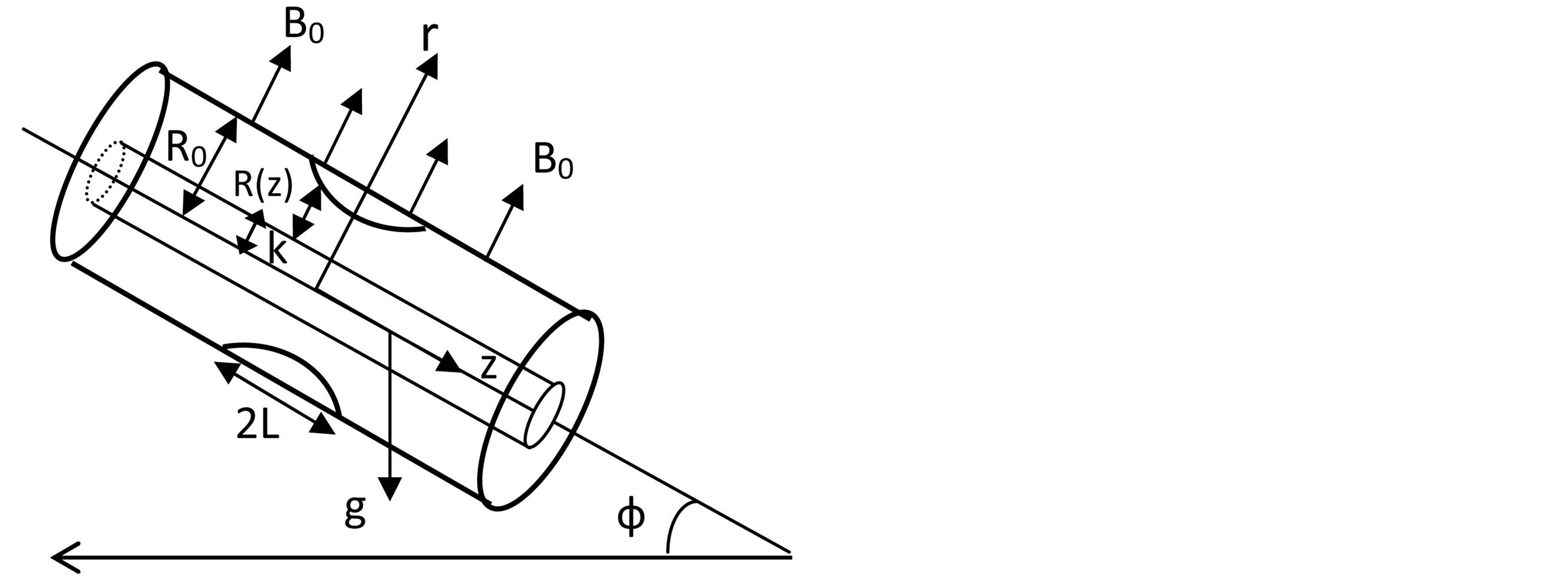
Figure 1. Schematic diagram of the studied physical model.
where, H the Hartmann number, Re the catheter speed based Reynold’s number.
On putting these parameters in the Equations (8) and (9), the equation of motion and boundary conditions in dimensionless form reduces to
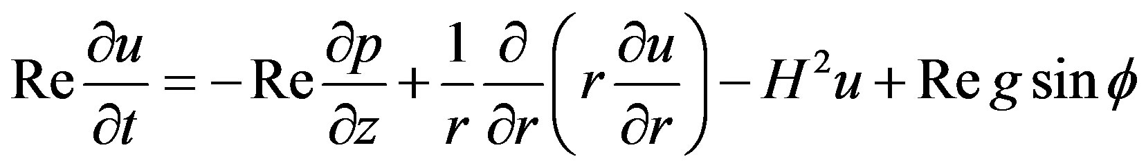 (11)
(11)
The corresponding boundary conditions are
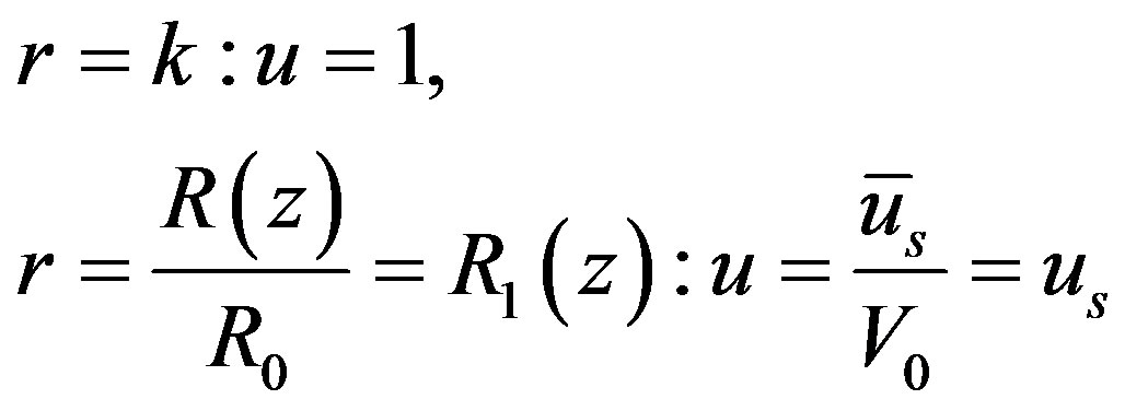 (12)
(12)
Let us assume the pressure gradient in the dimensionless form as
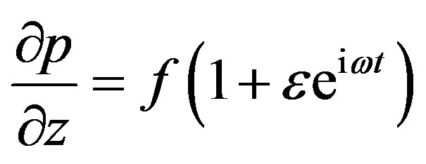 (13)
(13)
where, f is constant pressure gradient. The governing equation of motion is nonlinear coupled partial differential equation. For its solution, let us consider
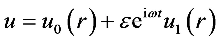 (14)
(14)
where ω is the frequency of the oscillations of pulsatile blood flow.
On plugging Equation (14) into Equation (11) and comparing coefficient of like powers of ε, we have zero-order and first order equations.
3.1. Zero-Order Equation
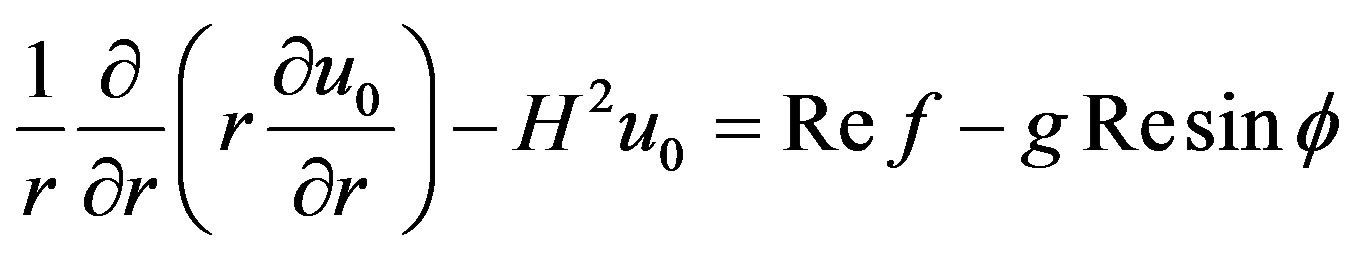 (15)
(15)
3.2. First Order Equation
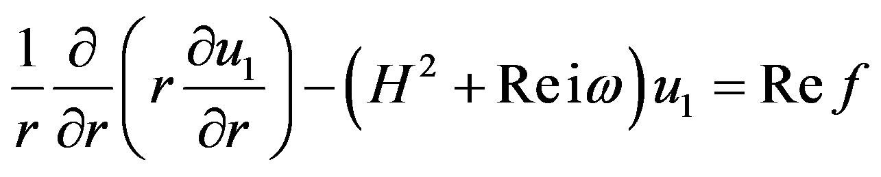 (16)
(16)
The corresponding boundary conditions are
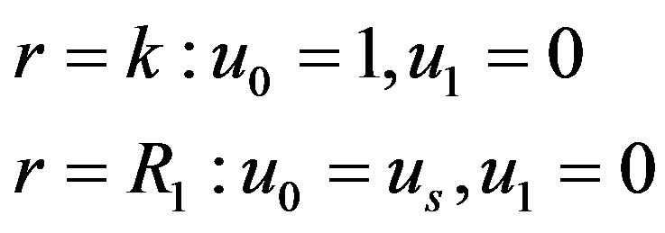 (17)
(17)
Equation (15) is the modified Bessel’s differential equation whose solution is given by
 (18)
(18)
where 
Similarly the solution of the Bessel’s Equation (16) for the transient flow is known and given by
 (19)
(19)
where,  and
and 
4. Calculation of Hemodynamic Indices Wss, Wssg, Volume Flow Rate and Impedance
4.1. Wall Shear Stress
Wall shear stress is important physical indicator for describing arterial disease due to disturbed flow. High Wall Shear Stress not only damage the vessel wall and cause intimal thickening, but also activate platelets, resulting platelet aggregation and thus formation of thrombus. Wall Shear Stress at the surface of stenosis is given by
 (20)
(20)
where,
4.2. Wall Shear Stress Gradient
Hemodynamic indicator describes the regions of disturbed flow which corresponds with high WSSG. Experimental results of Meng et al. [32] depict that high positive shear stress gradients encourage endothelial cell migration, which describe the region with low endothelial cell density prone to flow associated diseases. Based on simulated and realistic coronary artery models, Chaichana et al. [33] concluded that WSSG is a better hemodynamic indicator of atherosclerosis initiation as the regions of WSSG covered a larger region of disturbed flow. Mathematically the WSSG for unidirectional flow in the present model can be given by
 (21)
(21)
4.3. Volumetric Flow Rate
The volumetric flow rate Q of blood in the stenotic region is given by
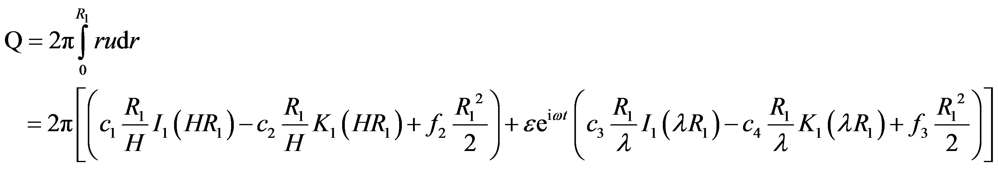 (22)
(22)
4.4. Resistive Impedance
The resistive impedance is physiological important hemodynamic indicator used in the study of resistance to flow of blood in artery. It is defined as
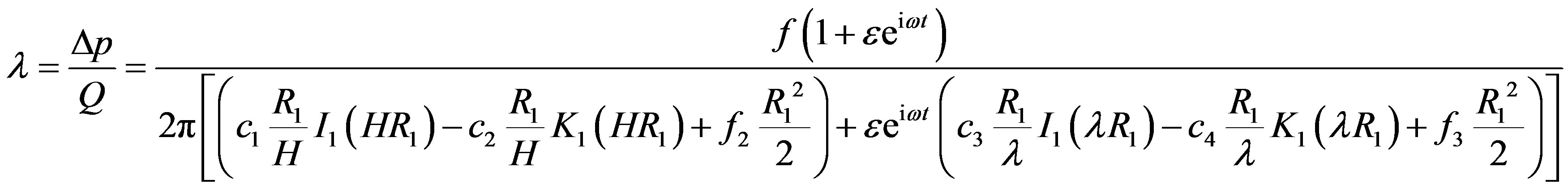 (23)
(23)
5. Results and Discussion
The flow profiles are derived for mild stenoses of thickness 20% of radius of artery. The catheter motion is taken in the positive z-direction.
Figure 2 shows that the effect of magnetic field reduces the flow speed result of which its gradient has been declined for higher value of Hartmann number (H).
Figure 3 depicts that with the increase of Reynolds number, i.e. on the increase of catheter speed, the flow velocity increases in both the cases, with slip or without slip at the wall of the artery. The slip at the arterial wall fairly increases the flow velocity as compare to the no-slip at the arterial wall. The effect of slip velocity at the arterial wall is more in magnitude at low Reynolds number (Re) and its effect diminished with the increase of
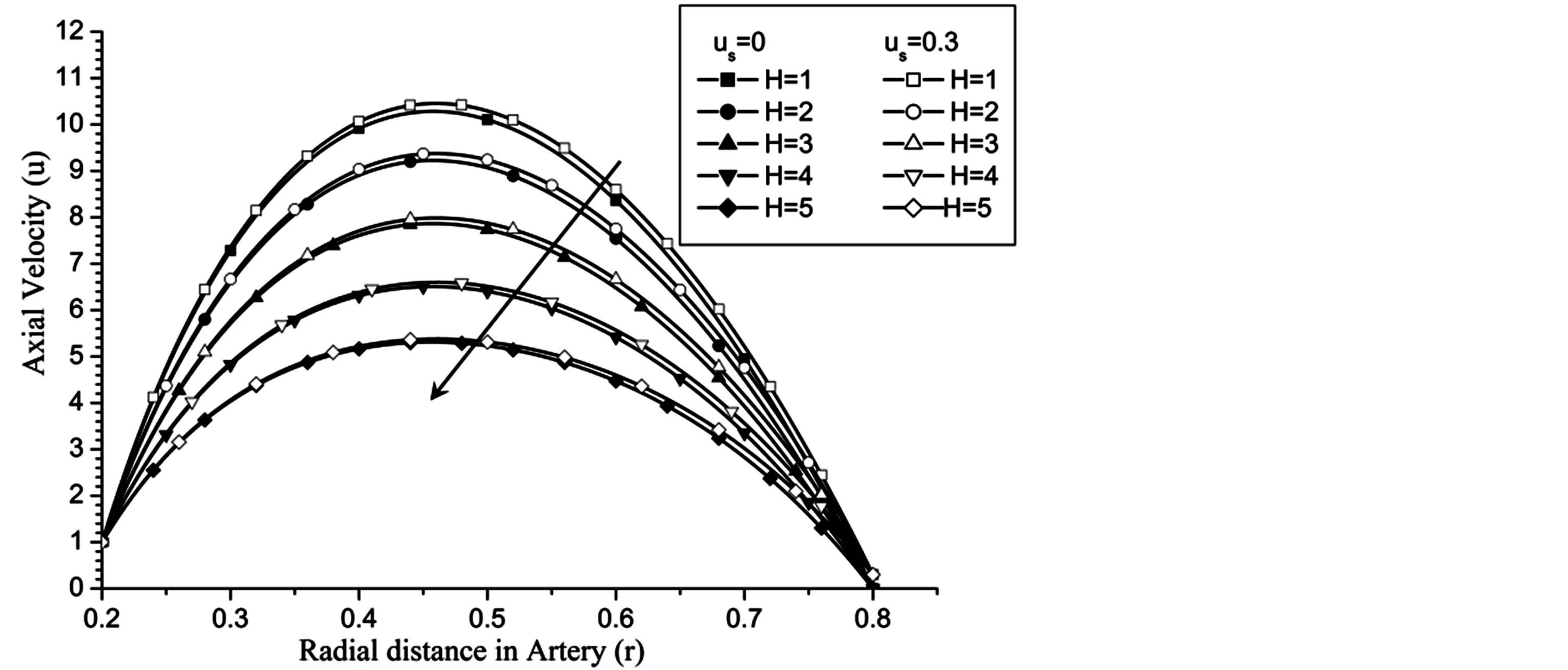
Figure 2. Variation of axial velocity for Hartmann number at Re = 100, g = 9.8 , z = 0.5, k = 0.2, ωt = π/3, ω = 1, φ = π/3.
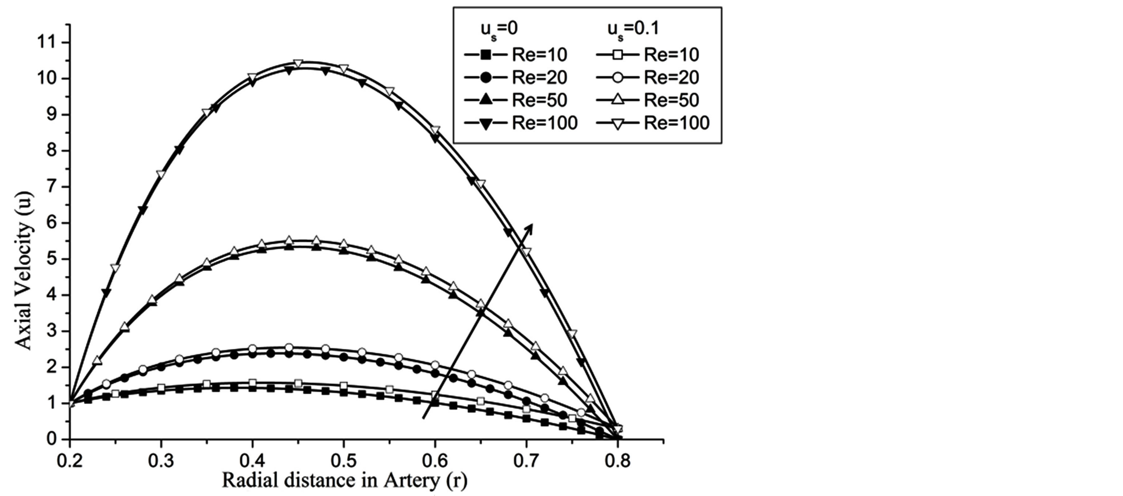
Figure 3. Variation of axial velocity for Reynolds number at H = 1, g = 9.8, z = 0.5, k = 0.2, ωt = π/3, ω = 1, φ = π/3.
Re. The increase in the angle of inclination  of the artery (Figure 1), the flow velocity augmented substantially at the core region of the annulus is observed in Figure 4. Figure 5 demonstrate that the flow in the annulus region is substantially affected by the aspect ratio (k) of catheter radius to radius of artery. The increase in the value of k produces more surface resistance resulted significant retardation in flow through annulus region. It is observed from Figure 6 that wall shear stress (WSS) increases with the increase in Hartmann number in the similar manner for both the cases of with slip or without slip at the arterial wall. At small value of H, the WSS with slip flow at the arterial wall is very close to its counter case of without slip flow at the wall while on increasing value of H the WSS is greater for slip flow case.
The WSS is reduces with the increase in the catheter speed based Reynolds number as observed in Figure 7. In view of physical model under consideration, the enhancement in flow velocity can be committed with increase in , that conclude the reduction in WSS with the increase of
  as depicted from Figure 8. The increase in the value of k produces more surface resistance resulted significant growth in the WSS as observed in Figure 9.
The volumetric flow rate (Q) diminishes with the increase of H is depicted from Figure 10 while Q enhanced with the increase of Re,  and aspect ratio k as observed from Figures 11-13 respectively.
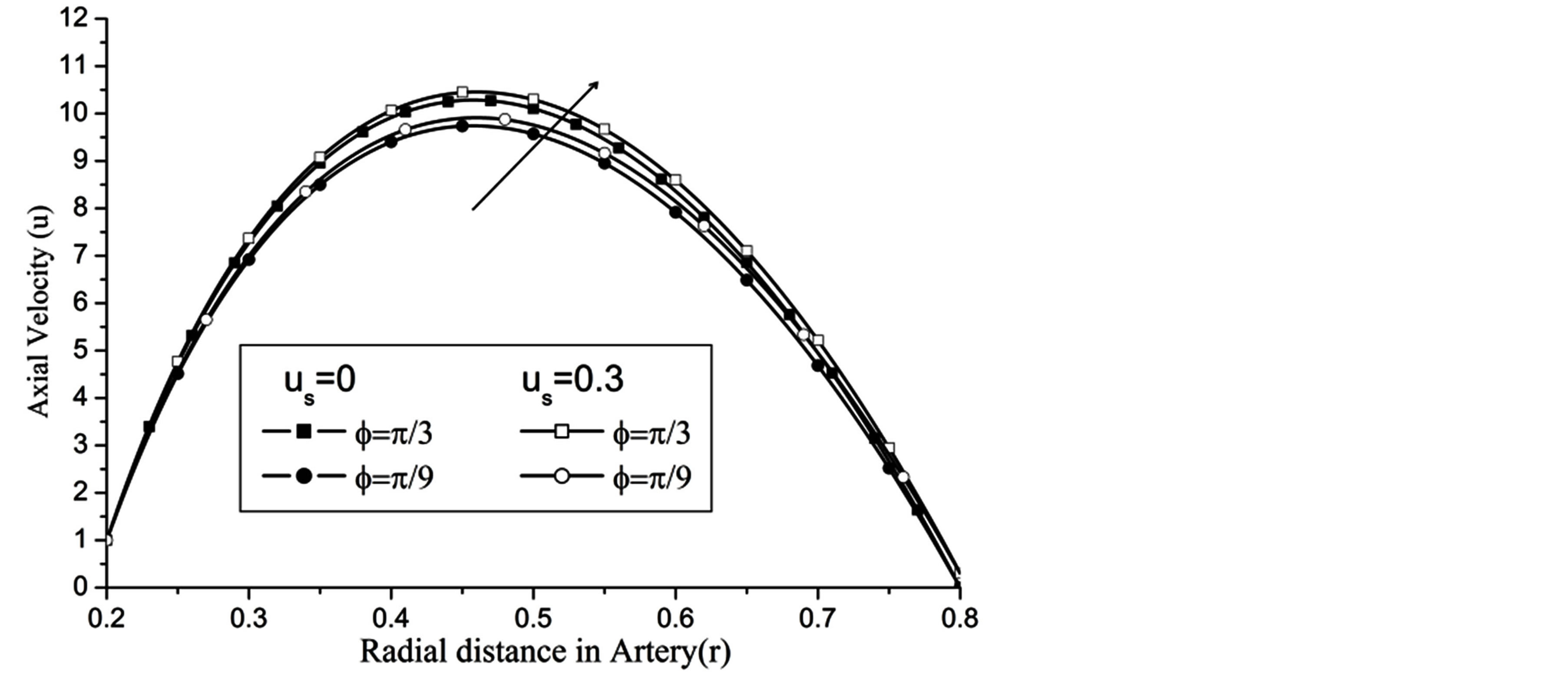
Figure 4. Variation of axial velocity for angle of inclination at Re = 100, g = 9.8, z = 0.5, k = 0.2, ωt = π/3, ω = 1, H = 1.
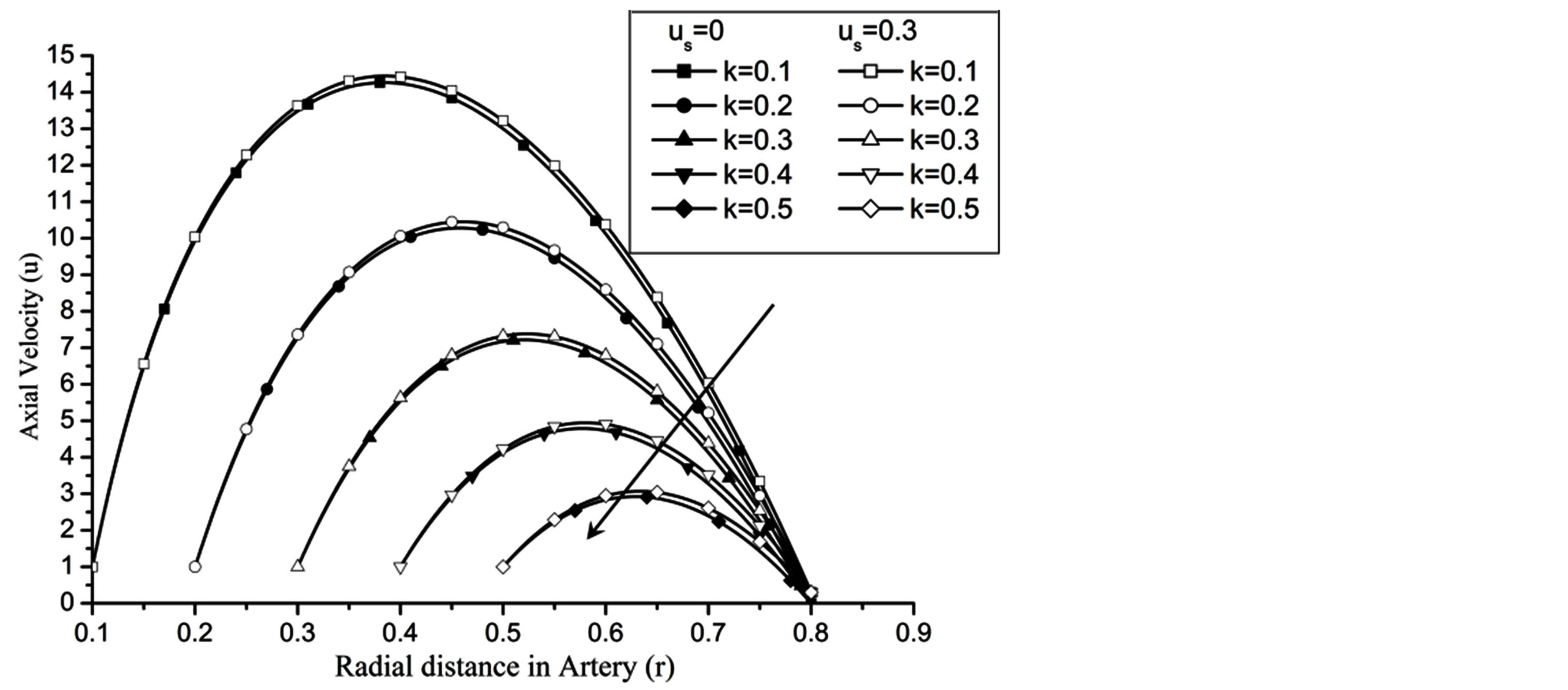
Figure 5. Variation of axial velocity for catheter radius at Re = 100, g = 9.8, z = 0.5, ωt = π/3, ω = 1, φ = π/3.
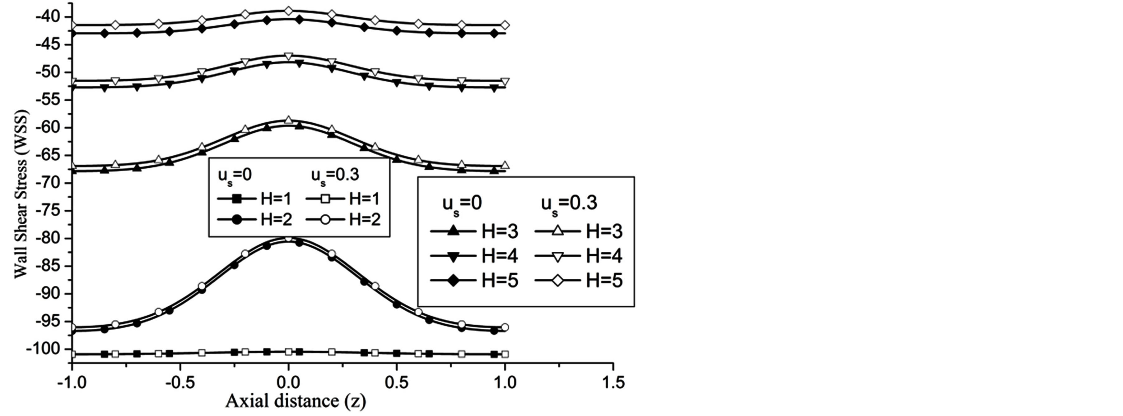
Figure 6. Variation of WSS for Hartmann number at Re = 100, g = 9.8, z = 0.5, k = 0.2, ωt = π/3, ω = 1, φ = π/3.
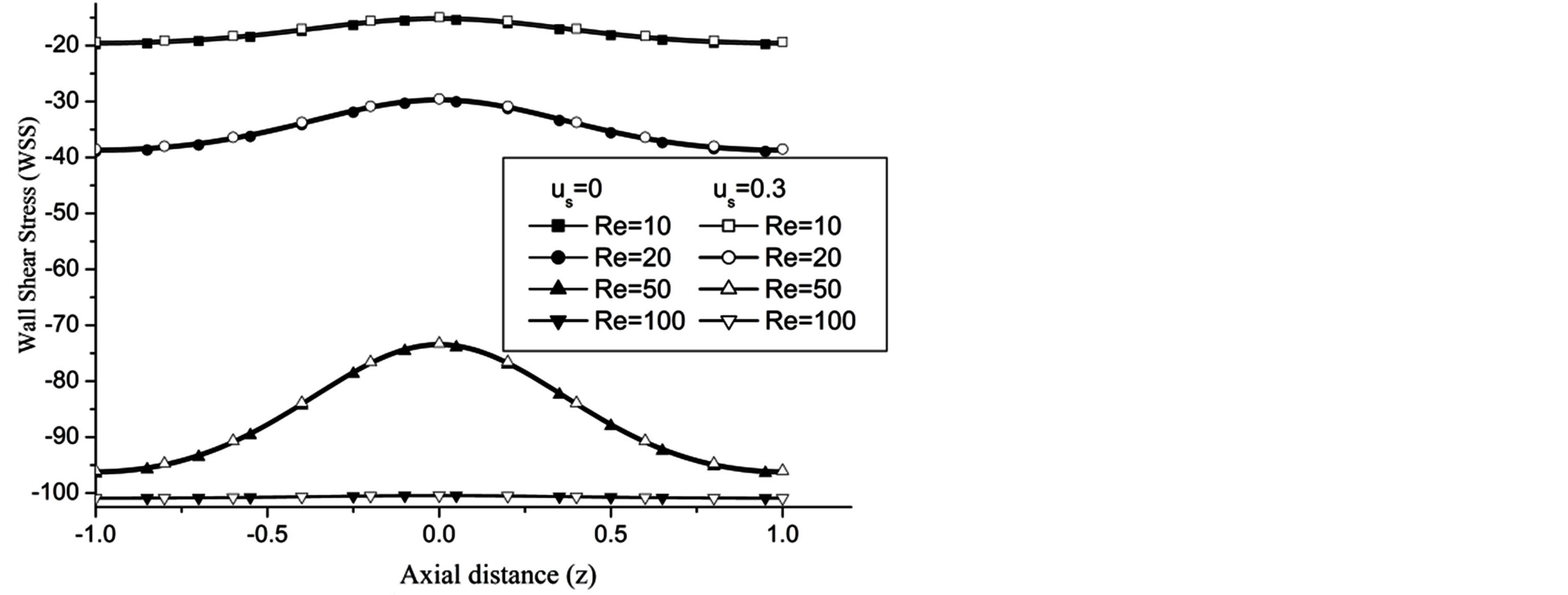
Figure 7. Variation of WSS for Reynolds number at H = 1, g = 9.8, z = 0.5, k = 0.2, ωt = π/3, ω = 1, φ = π/3.
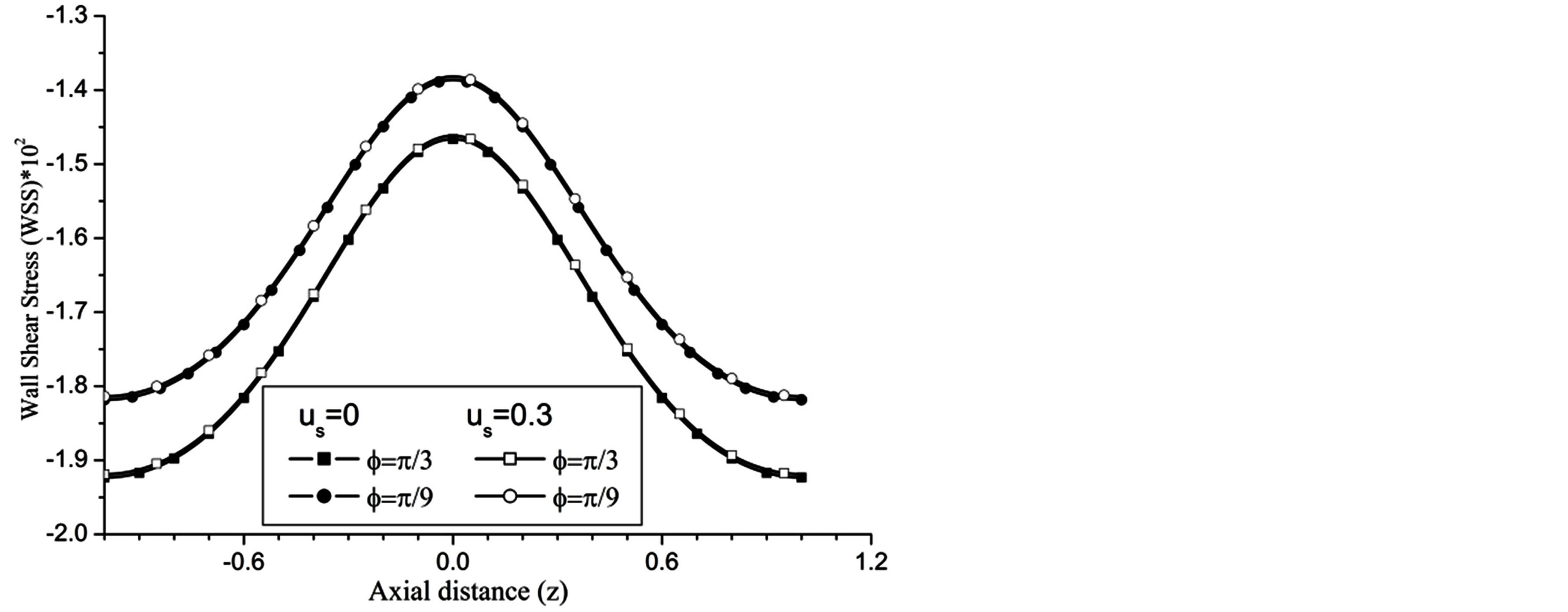
Figure 8. Variation of WSS for angle of inclination at Re = 100, g = 9.8, z = 0.5, k = 0.2, ωt = π/3, ω = 1, H = 1.
The wall shear stress gradient (WSSG) increases with the increase in H and Re as observed in Figures 14 and 15 respectively.
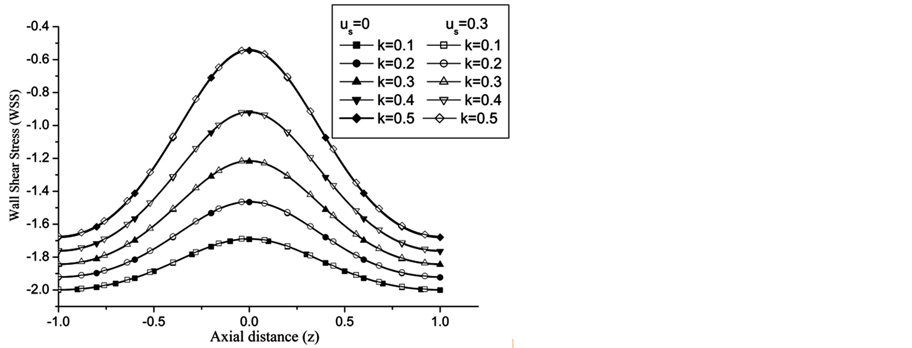
Figure 9. Variation of WSS for different values of radius of inner cylinder at Re = 100, H = 1, g = 9.8, z = 0.5, ωt = π/3, ω = 1, φ = π/3.
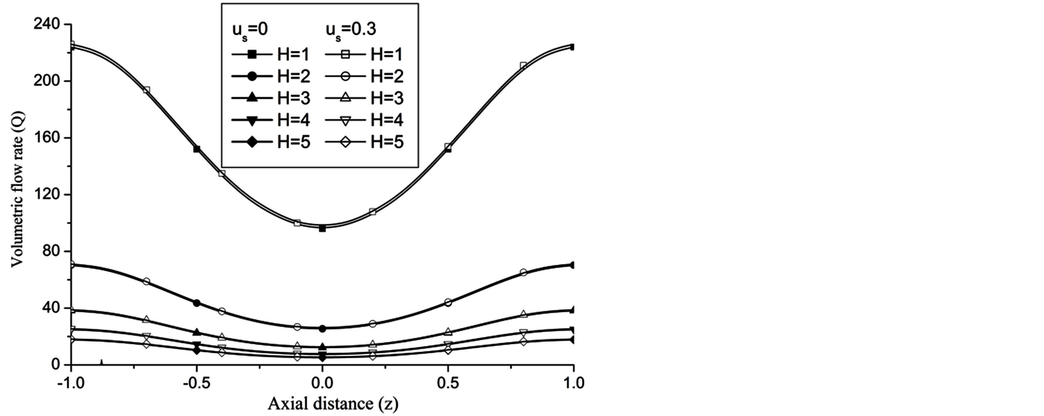
Figure 10. Variation of volumetric flow rate for Hartmann number at Re = 100, g = 9.8, z = 0.5, k = 0.2, ωt = π/3, ω = 1, φ = π/3.
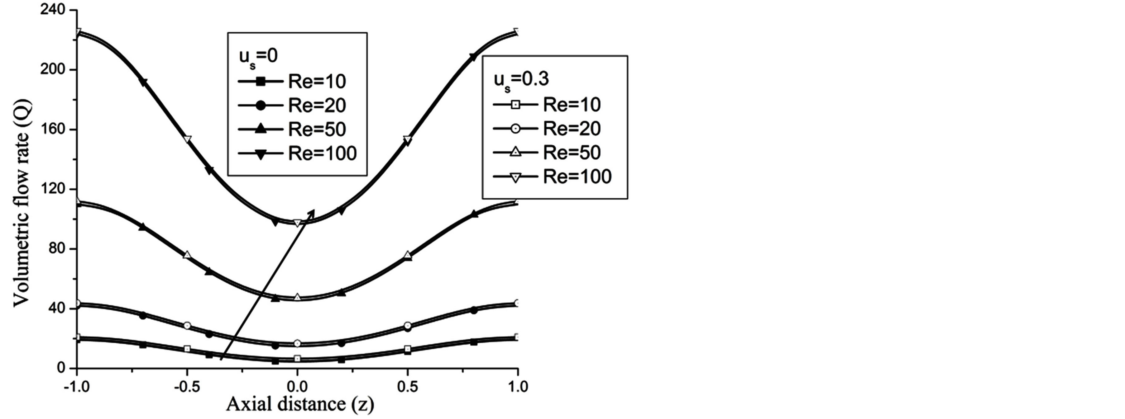
Figure 11. Variation of volumetric flow rate for Reynolds number at H = 1, g = 9.8, z = 0.5, k = 0.2, ωt = π/3, ω = 1, φ = π/3.
Figure 16 depict that WSSG decreases with the aspect ratio k.
Figures 17-19 demonstrate that the impedance 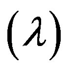 on the flow is significantly affected by H, Re and k
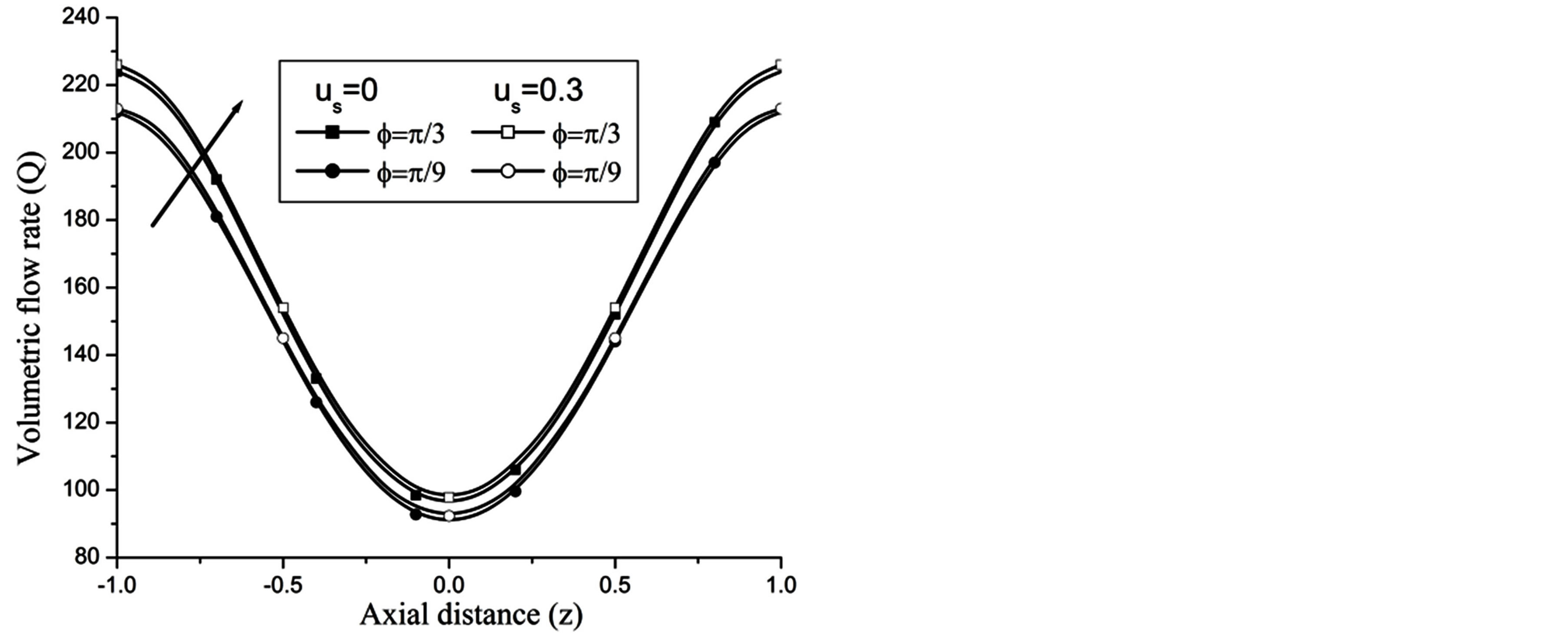
Figure 12. Variation of volumetric flow rate for angle of inclination at Re = 100, g = 9.8, z = 0.5, k = 0.2, ωt = π/3, ω = 1, H = 1.
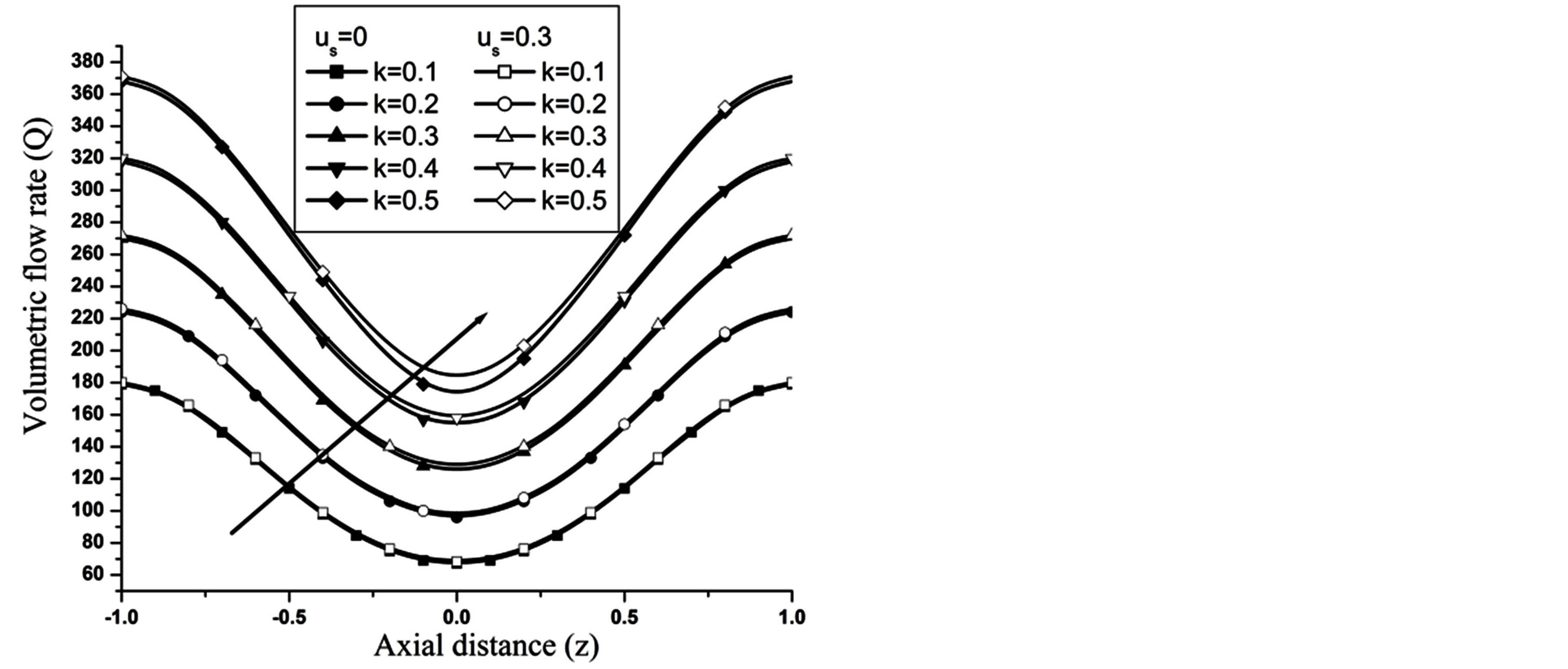
Figure 13. Variation of volumetric flow rate with catheter radius at Re = 100, g = 9.8, z = 0.5, k = 0.2, ωt = π/3, ω = 1, φ = π/3.
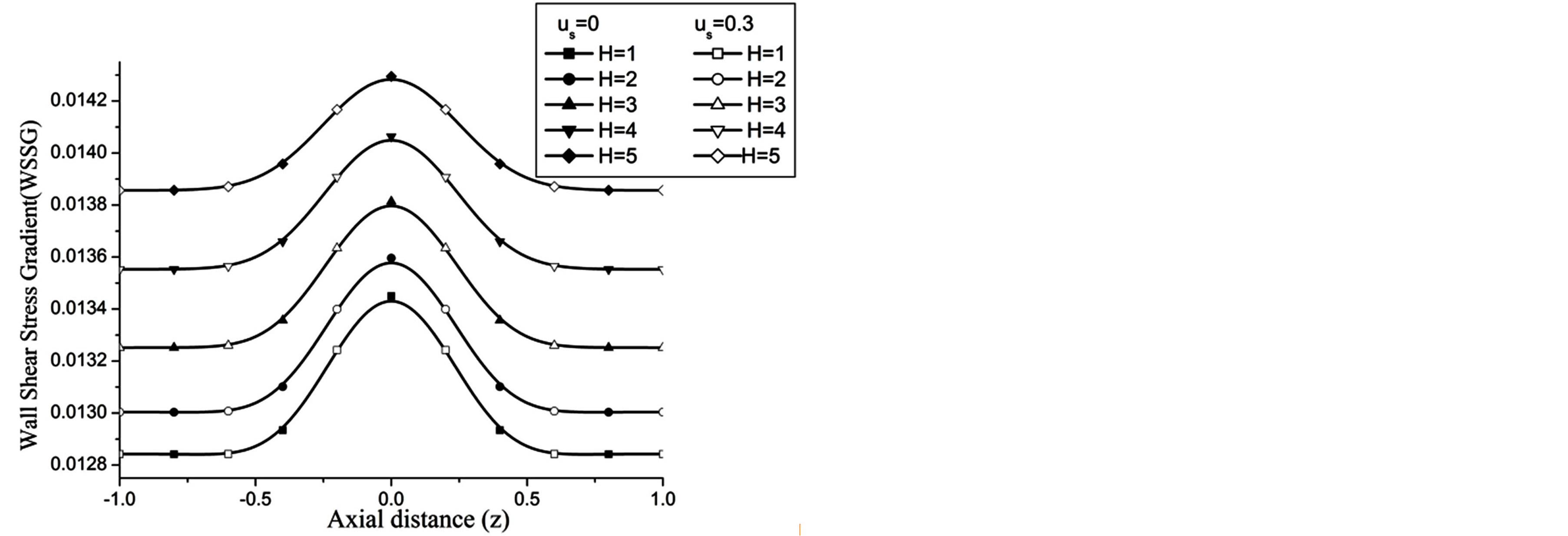
Figure 14. Variation of WSSG for Hartmann number at Re = 100, g = 9.8, z = 0.5, k = 0.2, ωt = π/3, ω = 1, φ = π/3.
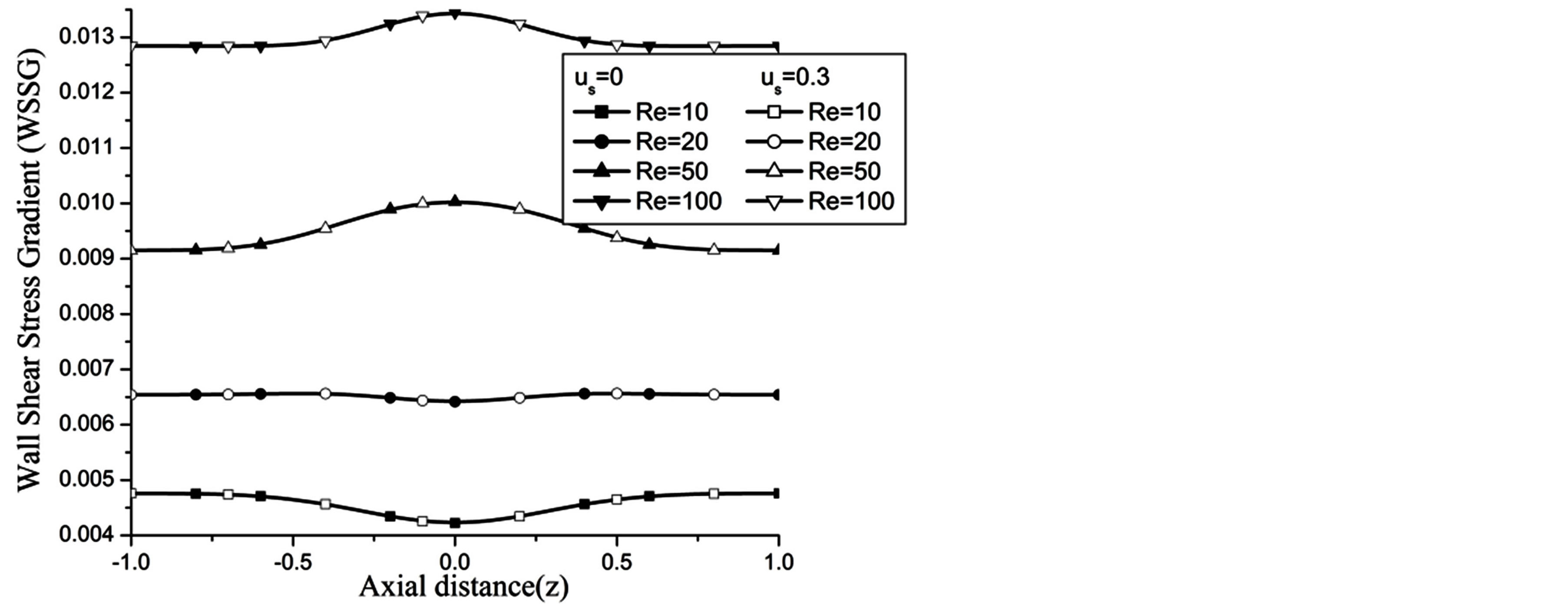
Figure 15. Variation of WSSG for Reynolds number at H = 1, g = 9.8, z = 0.5, k = 0.2, ωt = π/3, ω = 1, φ = π/3.
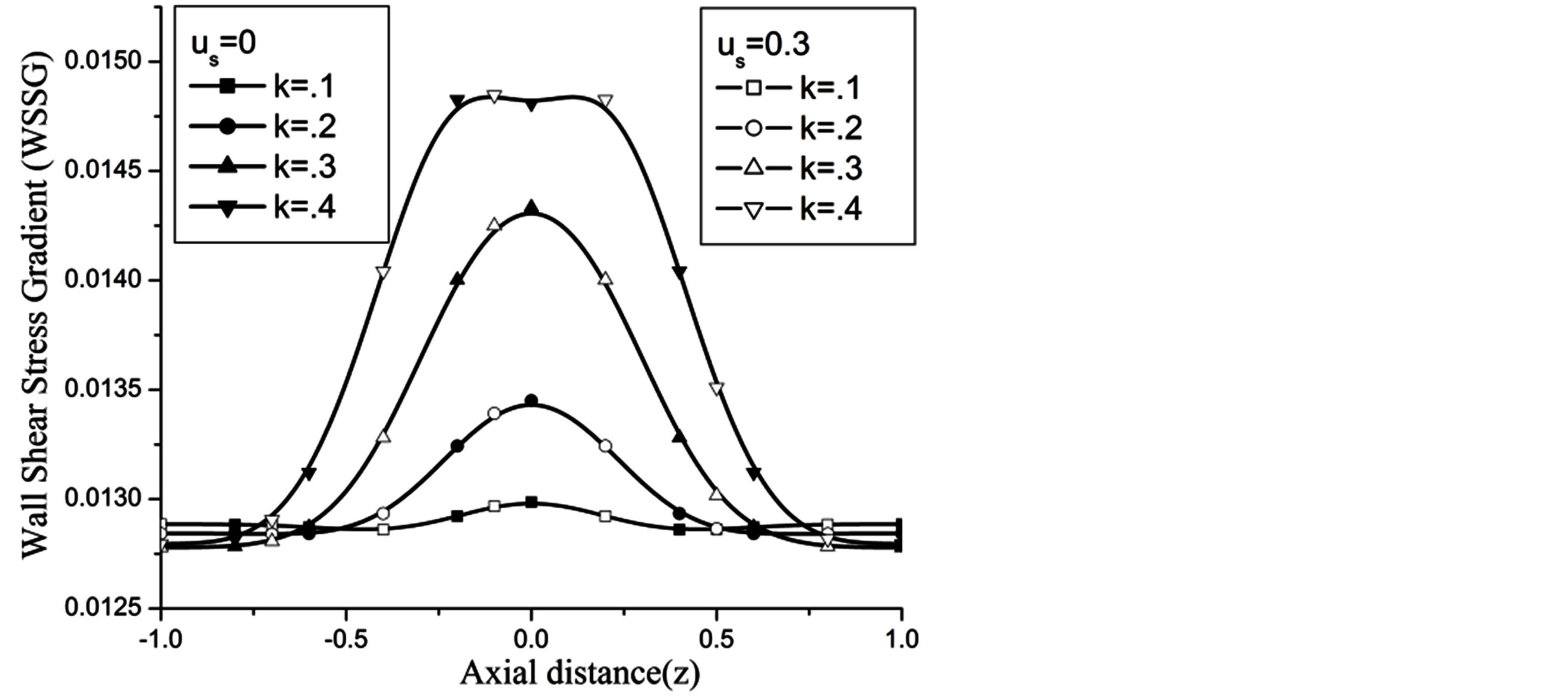
Figure 16. Variation of WSSG for catheter radius at Re = 100, g = 9.8, z = 0.5, k = 0.2, ωt = π/3, ω = 1, φ = π/3.
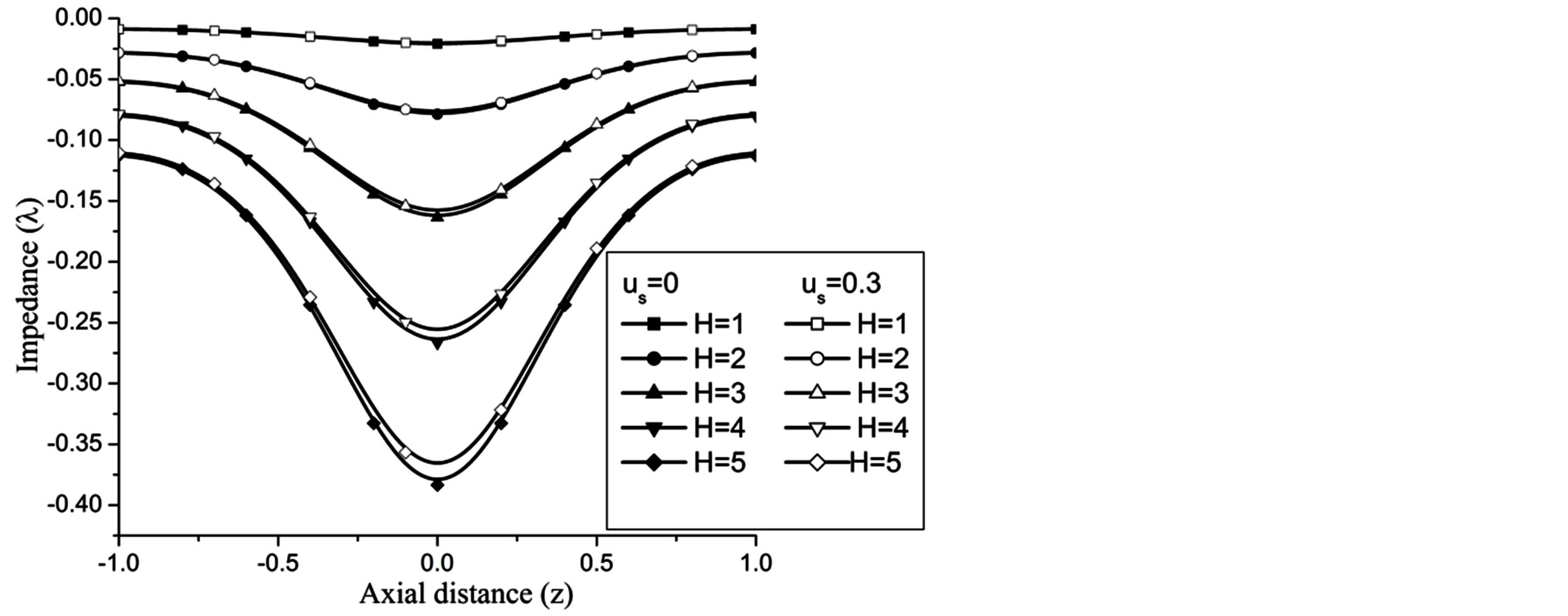
Figure 17. Variation of impedence for Hartmann number at Re = 100, g = 9.8, z = 0.5, k = 0.2, ωt = π/3, ω = 1.
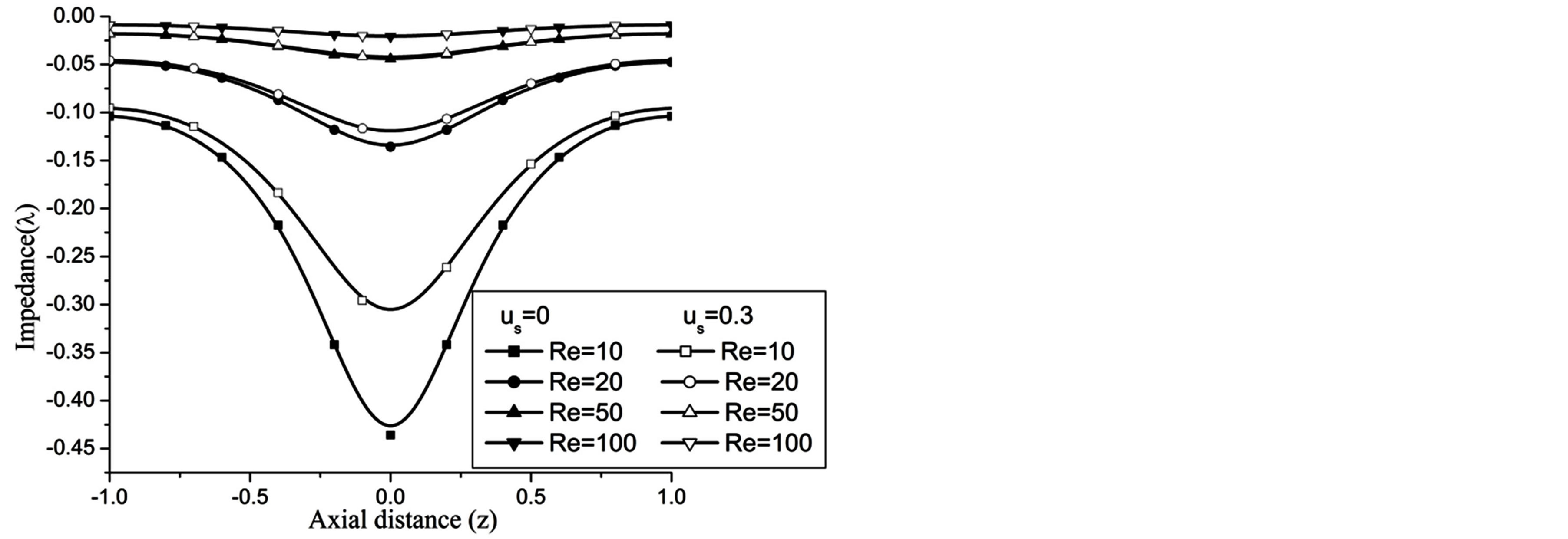
Figure 18. Variation of impedence for Reynolds number at H = 1, g = 9.8, z = 0.5, k = 0.2, ωt = π/3, ω = 1, φ = π/3.
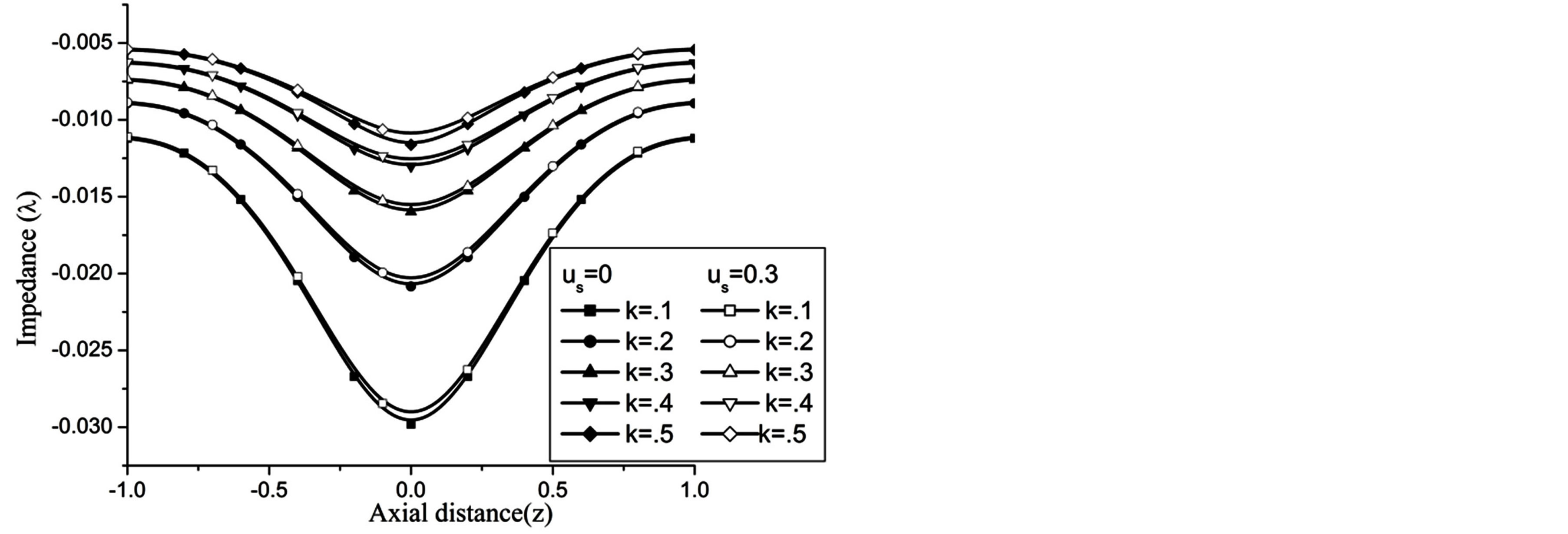
Figure 19. Variation of impedence for catheter radius at Re = 100, g = 9.8, z = 0.5, k = 0.2, ωt = π/3, ω = 1, φ = π/3.
throughout in the stenosis region of artery.
At the maximum height of stenosis  is appreciably diminishes with the increase of H, is in good agreement with the results of Mekheimer and Kot [10] . The impedance on the flow in annulus has augmented with the increase of Re and k, shown in the Figures 18 and 19 respectively.
Ÿ 6. Conclusions
Ÿ Wall shear stress increases with increasing transverse magnetic field.
Ÿ WSSG high at the apex of the stenosis indicates more disturbed flow at this location.
Ÿ The impedance at the apex of the stenosis reduces increasing transverse magnetic field strength.
Ÿ The impedance on the flow in annulus has augmented with the increase of Re and k.
References
- Fung, Y.C. (1984) Biodynamics Circulation. Springer-Verlag, New York.
- McDonald, D.A. (1960) Blood Flow in Arteries. Arnold, London.
- Mazumdar, J.N. (1992) Bio-fluid Mechanics. Word Scientific Press.
- Zamir, M. (2005) The Physics of Coronary Blood Flow. Springer, New York.
- Young, D.F. (1979) Fluid Mechanics of Arterial Stenoses. Journal of Biomechanical Engineering, 101, 157-175. http://dx.doi.org/10.1115/1.3426241
- Srivastava, V.P. (1996) Two Phase Model of Blood Flow through Stenosed Tubes in the Presence of a Peripheral Layer: Applications, Journal of Biomechanics, 29, 1377-1382. http://dx.doi.org/10.1016/0021-9290(96)00037-1
- Srivastava, V.P. (2002) Particulate Suspension Blood Flow through Stenotic Arteries: Effect of Hematocrit and Stenosis Shape. Indian Journal of Pure and Applied Mathematics, 33, 1353-1360.
- Liu, Z.-R., Xu, G., Chen, Y., Teng, Z.-Z. and Qin, K.-R. (2003) An Analysis Model of Pulsatile Blood Flow in Arteries. Applied Mathematics and Mechanics, 24, 230-240. http://dx.doi.org/10.1007/BF02437630
- Yao, L. and Li, D.-Z. (2006) Pressure and Pressure Gradient in an Axisymmetric Rigid Vessel with Stenosis. Applied Mathematics and Mechanics (English Edition), 27, 347-351. http://dx.doi.org/10.1007/s10483-006-0310-z
- Mekheimer, Kh.S. and El Kot, M.A. (2008) Influence of Magnetic Field and Hall Currents on Blood Flow through a Stenotic Artery. Applied Mathematics and Mechanics (English Edition), 29, 1093-1104.
- Kanai, H., Lizuka, M. and Sakamotos, K. (1996) One of the Problem in the Measurement of Blood Pressure by Catheterization: Wave Reflection at the Tip of Catheter. Medical & Biological Engineering, 28, 483-496.
- Back, L.H., Kwack, E.Y. and Back, M.R. (1996) Flow Rate-Pressure Drop Relation in Coronary Angioplasty: Catheter Obstruction Effect. Journal of Biomechanical Engineering, 118, 83-89.
- Jones, A.L. (1966) On the Flow of Blood in a Tube. Biorheology, 3, 183-188.
- Nubar, Y. (1967) Effects of Slip on the Rheology of a Composite Fluid: Application to Blood Flow. Rheology, 4, 133- 150.
- Brunn, P. (1975) The Velocity Slip of Polar Fluids. Rheologica Acta, 14, 1039-1054. http://dx.doi.org/10.1007/BF01515899
- Bugliarello, G. and Sevilla, J. (1970) Velocity Distribution and Other Characteristics of Steady and Pulsatile Blood Flow in Fine Glass Tubes. Biorheology, 7, 85-107.
- Bennet, L. (1967) Red Cell Slip at a Wall in Vitro. Science, 155, 1554-1556. http://dx.doi.org/10.1126/science.155.3769.1554
- Misra, J.C. and Shit, G.C. (2007) Role of Slip Velocity in Blood Flow through Stenosed Arteries: A Non-Newtonian Model. Journal of Mechanics in Medicine and Biology, 7, 337-353. http://dx.doi.org/10.1142/S0219519407002303
- Ponalgusamy, R. (2007) Blood Flow through an Artery with Mild Stenosis: A Two-Layered Model, Different Shapes of Stenoses and Slip Velocity at the Wall. Journal of Applied Sciences, 7, 1071-1077. http://dx.doi.org/10.3923/jas.2007.1071.1077
- Moreau, R. (1990) Magneto-Hydrodynamics. Kluwer Academic Publishers, Dordrecht.
- Kolin, A. (1936) An Electromagnetic Flowmeter: Principle of Method and Its Application to Blood Flow Acceleration , Experimental Biology and Medicine, 35, 53-56. http://dx.doi.org/10.3181/00379727-35-8854P
- Barnothy, M.F. (1964) Biological Effects of Magnetic Fields. Plenum Press, New York.
- Korchevskii, E.M. and Marochnik, L.S. (1965) Magneto Hydrodynamic Version of Movement of Blood. Biophysics, 10, 411-413.
- Halder, K. and Ghosh, S.N. (1994) Effects of a Magnetic Field on Blood Flow through an Intended Tube in the Presence of Erythrocytes. Indian Journal of Pure and Applied Mathematics, 25, 345-352.
- McKay, J.C., Prato, F.S. and Thomas, A.W. (2007) A Literature Review: The Effects of Magnetic Field Explore on Blood Flow and Blood Vessels in the Microvasculature. Bioelectromagnetics, 28, 81-98. http://dx.doi.org/10.1002/bem.20284
- Tzirtzilakis, E.E. (2005) A Mathematical Model for Blood Flow in Magnetic Field. Physics of Fluids, 17, 1-15. http://dx.doi.org/10.1063/1.1978807
- Layek, G.C. and Mukhopadhyay, S. (2008) Numerical Modeling of a Stenosed Artery Using Mathematical Model of Variable Shape. International Journal of Applications and Applied Mathematics, 3, 308-328.
- Kumar, S., Sharma, M.K., Singh, K. and Garg, N.R. (2011) MHD Two-Phase Blood Flow through an Artery with Axially Non-Symmetric Stenosis. International Journal of Mathematical Sciences & Engineering Applications (IJMSEA), 5, 63-74.
- Mekheimer, Kh.S. (2003) Non-Linear Peristaltic Transport of Magnetohydrodynamic Flow in an Inclined Planar Channel. The Arabian Journal for Science and Engineering, 28, 183-201.
- Tashtoush, B. and Magableh, A. (2008) Magnetic Field Effect on Heat Transfer and Fluid Flow Characteristics of Blood Flow in Multi-Stenotic Arteries. Heat and Mass Transfer, 44, 297-304. http://dx.doi.org/10.1007/s00231-007-0251-x
- Cowling, T.G. (1957) Magnetohydrodynamics. Interscience Publishers, New York.
- Meng, H., Swartz, D.D., Wang, Z., Hoi, Y., Kolega, J., Metaxa, E.M., Szymanski, M.P., Yamamoto, J., Sauvageau, E. and Levy, E.I. (2006) A Model System for Mapping Vascular Responses to Complex Hemodynamics at Arterial Bifurcations in Vivo. Neurosurgery, 59, 1094-1101. http://dx.doi.org/10.1227/01.NEU.0000245599.92322.53
- Chaichana, T., Sun, Z. and Jewkes, J. (2011) Computation of Hemodynamics in the Left Coronary Artery with Variable Angulations. Journal of Biomechanics, 44, 1869-1878. http://dx.doi.org/10.1016/j.jbiomech.2011.04.033