Positioning
Vol.4 No.1(2013), Article ID:28381,6 pages DOI:10.4236/pos.2013.41005
LQR Controller with Kalman Estimator Applied to UAV Longitudinal Dynamics
![]()
Aeronautical & Astronautical Engineering Department, Istanbul Technical University, Istanbul, Turkey.
Email: cingiz@itu.edu.tr, yenalvural@gmail.com
Received November 26th, 2012; revised December 30th, 2012; accepted January 10th, 2013
Keywords: Unmanned Air Vehicle; LQR Controller; Kalman Filter; Stability Analysis
ABSTRACT
The aim of this study is designing an optimal controller with linear quadratic regulator (LQR) method for a small unmanned air vehicle (UAV). To better evaluate the effect of disturbances on the obtained measurements, a Kalman filter is also used in the system. For this purpose a small UAV that is normally used as a radio controlled plane is chosen. The linearized equations for a wings level flight condition and the state space matrices are obtained. An optimal controller using LQR method to control the altitude level is then designed. The effect of the disturbances on the measurements are taken into account and the effectiveness of the Kalman filter in obtaining the correct measurements and achieving the desired control level are shown using the controller designed for the system. The small UAV is commanded to the desired altitude using the LQR controller through the control inputs elevator deflection and thrust rate. The LQR effectiveness matrices are chosen to find the gains necessary to build an effective altitude controller. Firstly the controller is tested under the situation where disturbances are absent. Then a Kalman filter is designed and the system under disturbances is tested with the designed controller and the filter. The results reveal the effectiveness of the Kalman filter and the LQR controller.
1. Introduction
Unmanned air vehicles (UAVs) have become a popular research subject in the last years. These vehicles can be used for many different missions including rescue, data gathering and military missions.
To design a control system for an UAV defining the dynamic model and finding the aerodynamic coefficients are the first steps. The non-linear model can then be linearized to design a linear controller for the UAV [1]. The characteristic values of different motions which show how the aircraft normally behaves must also be investigated at this stage. Finally the controller and filter can be designed considering the required specifications.
The optimal control technique linear quadratic regulator (LQR) is chosen to design a controller for the longitudinal motion of a small fixed-wing type UAV. Kalman filter technique is then applied to see how the controller is affected by disturbances. The effectiveness of the controller with and without the Kalman filter is also shown through simulations. Linear quadratic control is an optimal control technique that is used for controlling the aircraft. This control technique aims to decrease the energy that is used to control the aircraft. This technique can be applied together with a filtering technique (Kalman filter etc.) in cases where some of the states are not available for measurement or when the measurements are noisy.
Studies that include LQR control design for different types of aircraft are present [2]. In [3], a linear, quadratic regulator method is used to control the trajectory and mission paths of the autonomous helicopter. Nonlinear motion dynamics is linearized at certain operating points and linear model is obtained by Taylor’s series expansion. By using LQR methodology, the attitude of the autonomous Puma helicopter is controlled. The study [4] shows that the LQR controller is quite effective in the vertical flight mode for all possible yaw angles. In [5] the design procedure for a gain-scheduled LQR controller for an autonomous airship is presented. Two types of control sub-systems (lateral, longitudinal) have been designed from the nonlinear 6DOF airship model to fulfill different goals (yaw as well as speed and position control). In references [2-5], LQR controller is not applied together with a filtering technique.
In some studies filtering techniques are used to analyze the effects of LQR design and increase the effectiveness of the controller. The paper [6] depicts the application of linear quadratic optimal control to the longitudinal flight motion of an UAV which has elevon control only. The LQR controller followed by a Kalman filter based estimator for unmeasurable states. The LQR controller is then combined with the Kalman estimator using the separation principle to investigate the feasibility of altitude control. The simulation results show improvements compared with classical design counterparts in the sense that the combined approach offers more design flexibility and is able to tolerate the noisy environments.
Some advanced techniques including robust and adaptive control techniques are also used in UAV control. For example in one study by Johnson and Calise, Hinfinity technique is used to design a velocity and altitude controller that follows a determined model [7]. However in this study these advanced techniques are only investigated to design a better controller and are not used.
In this study an altitude controller is designed for a small UAV using the optimal LQR control method with Kalman estimator. Finally the effectiveness of the controller with the gains found by LQR method is investigated under the effect of disturbances and with the Kalman filter.
2. Mathematical Model of the UAV
In this study the longitudinal motion of the small UAV is investigated. We can find the longitudinal equations of motion for the UAV by linearizing the equations for wings-level flight.
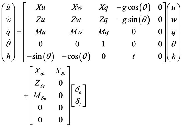
The longitudinal state model is given below:
 (1)
(1)
where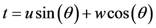 ,
,  and
and  are the elevator and throttle control inputs, u is the forward velocity, w is the vertical velocity, q is the pitch rate, θ is the pitch angle and h is the altitude,
  ,
,  ,
,  ,
,  ,
,  ,
,  ,
,  ,
,  ,
,  and
and ,
,  ,
,  ,
,  are the dimensional stability derivatives.
The mathematical model (1) can be presented in the matrix form:
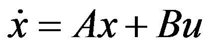 . (2)
. (2)
where 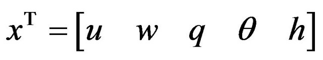 is the state vector of the longitudinal motion of UAV,
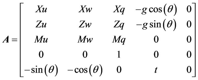
is the system transition matrix,
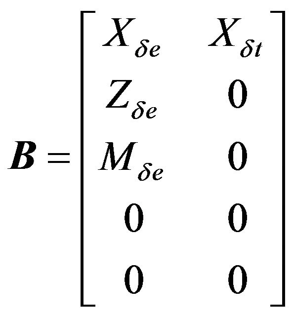
is the control distribution matrix and  is the vector of control input.
3. Stability Analysis
Characteristic equations are investigated firstly to analyze the stability of the UAV. The longitudinal equations can be calculated using the transfer functions. The characteristic equation for the longitudinal motion is as follows:
 (3)
(3)
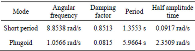
Longitudinal motion can be represented by two different modes, namely short period and phugoid mode. Phugoid mode has the characteristic of longer period times and lower damping factors and can be easily controlled. Phugoid mode can be described as the change in kinetic and potential energy in which attack angle changes are significantly smaller than the changes in velocity and pitch angle. Short period mode occurs in a smaller time period where the change in pitch and attack angles are significant and it also has high damping factor. The longitudinal roots show a stable motion. Some of the characteristic values for these longitudinal motions are given in Table 1.
4. LQR Application for the UAV
In this study, LQR is adopted as an optimal control technique for the UAV. Considering a system with state space model (2), the optimal control vector is as follows:
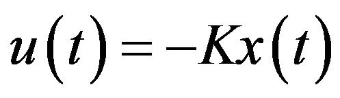 (4)
(4)
In order to determine the optimal control inputs, while optimizing the state variables at the same time, the following cost function (also called quadratic performance index) has to be minimized [8],
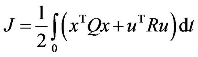 (5)
(5)
Table 1. Characteristic values of the longitudinal motion.
where Q is a semi-positive definite symmetric matrix and R is a positive definite symmetric matrix. Q and R weight matrices are chosen to control each state effectively using little control effort according to the performance index (5).
The gain matrix of the optimal control vector can be computed by the following equation:
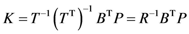 (6)
(6)
Therefore, optimal control equation becomes:
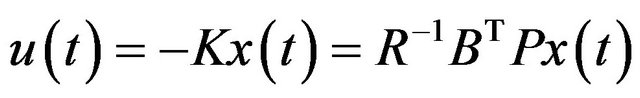 (7)
(7)
If one positive definite P matrix can be calculated by the following Ricatti equation then the system is said to stable:
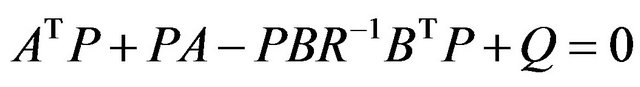 (8)
(8)
Under some special conditions the LQR controller can be designed using the Riccati Equation (8) without changing the state and control matrices to find the optimal gain matrix [8].
The optimal filter can also be considered in cases where some unknown states are present [9].
For this system without adding an integrator we can use the previously determined A and B matrices together with the control and state weight matrices Q and R to find the optimal gain matrix K that will let us find the control input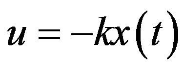 .
.
LQR height controller simulation results are shown in Figures 1-3. The altitude change input (20 m) is used in
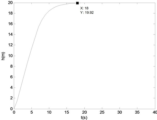
Figure 1. LQR controller result in altitude (Q1 is used).
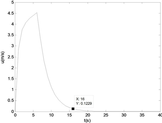
Figure 2. LQR controller result in forward velocity (Q1 is used).
Figure 3. LQR controller result in forward velocity (Q is used).
the simulations. Also the effect of using different weight matrices is shown using different Q matrices.
The effectiveness matrices used in LQR controller are given below:
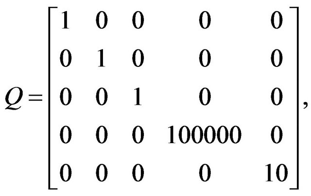
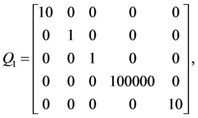
 .
.
It is understood that LQR controller works well for longitudinal UAV control system. By changing Q we may change the results of the state variables according to the requirements. With Q1 as can be seen in Figure 2 little change in forward velocity can be achieved.
5. Kalman Filter for UAV State Estimation
In this study an LQR controller is designed without taking the effect of the disturbances on the measurements. The system equations are discretized using the Euler approach. Firstly the LQR altitude controller without the effect of disturbances is tested then the response of the system with the controller under the disturbances is tested with and without Kalman filter. The effectiveness of the Kalman filter is shown using the results.
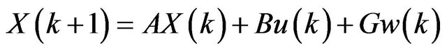
Kalman filter uses state equations (state space matrices) and initial values to calculate the residue and gain values and to estimate the real signal value. The steps of the Kalman filter can be explained using linear discretized state and measurement equations:
 (9)
(9)
 (10)
(10)
In the state equation  is the state vector of the system, A is the system transition matrix,
  is the input vector, B is the control distribution matrix,
  is the random Gaussian noise vector (system noise) with zero mean and known covariance structure, G is the transition matrix of the system noise. In the measurement equation
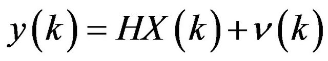
  is the measurement vector, H is the measurement matrix,
  is the measurement noise vector with zero mean and known covariance structure. There is no correlation between the system noise
  and the measurement noise
 . The covariance matrices for the
  and
and  vectors are given by:
Here E is the expected value operator,  is the Kronecker symbol.
The optimum linear Kalman filter that estimates the state vector of the system (9) is expressed with the following recursive equations system:
Equation of the extrapolation value,
 (11)
(11)
The innovation sequence,
 (12)
(12)
Equation of the estimation value,
 (13)
(13)
Gain matrix of the optimum linear Kalman filter,
 (14)
(14)
The covariance matrix of the filtering error is,
 (15)
(15)
The covariance matrix of the extrapolation error is,
 (16)
(16)
where  is the desired vector, I is the identity matrix.
Kalman filter tries to estimate the real signal from the signal with disturbance which has Gaussian distribution using the described steps and decreasing the value between two signals [9,10].
6. Simulations of LQR Controller with Kalman Estimator
The model of longitudinal motion (2) can be discretized using Euler approach and determining time period dt. Thus the new discretized A and B matrices to be used in the filtering approach can be found by  and
and .
.
The discretized UAV model can be given as follows:
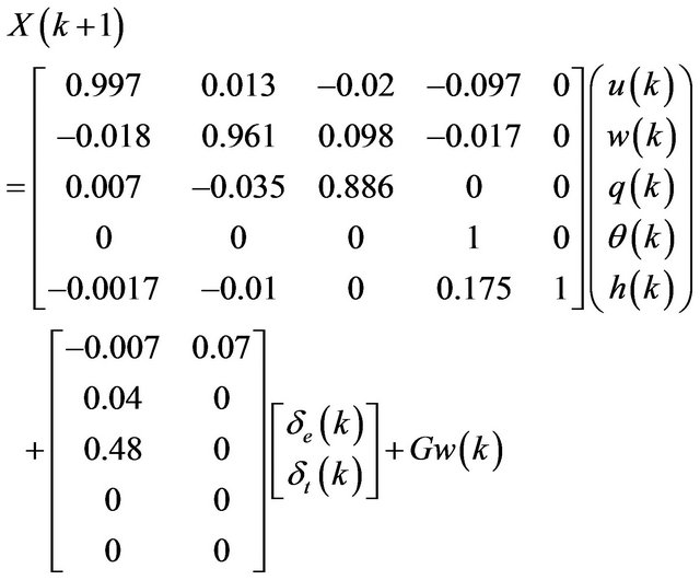 (17)
(17)
 (18)
(18)
In our case disturbance with Gaussian white noise characteristics generated by Matlab commands is applied to the real values found using our UAV model. Kalman filtering technique is then applied and its effectiveness is shown. In the real scenario the disturbances in measurements and process is usual and have an effect on the controller. Thus using a filtering technique is important.
The values of the states can be calculated using Equation (17) that includes the control rule. The disturbances on the states of course must be determined firstly and applied to the system. Finally Kalman filter can be applied to the system with the disturbances to develop an effective controller. To do this a Matlab code is written. The results are given in Figures 4-7. The Kalman filter that works as an optimal observer is estimating the new values of the states correctly and decreasing the error.
As seen from Figures 4-7, in case of disturbances, using a Kalman filter to estimate the values of the states clearly increase the effectiveness of the LQR controller.
7. Conclusion
In this study an altitude control system is designed for a small UAV using the optimal control method LQR. This method which is effective in controlling the longitudinal motion of the UAV is based on the acceptance that all

Figure 4. Change in altitude with LQR controller and Kalman filter.
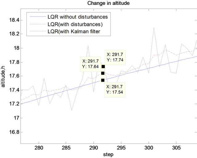
Figure 5. Change in altitude with LQR controller and Kalman filter (zoomed view).

Figure 6. Error differences in altitude with disturbances (with KF).
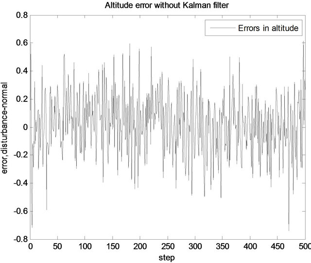
Figure 7. Error differences in altitude with disturbances (without KF).
states can be measured truly however in real cases it is not generally possible. To make the controller more effective Kalman filter approach is used in the study. A Kalman filter is designed and added to the system and the response of the controller with and without disturbances and the Kalman filter is tested. The simulations show that in case of disturbances using a Kalman filter to estimate the values of the states clearly increase the effectiveness of the LQR controller. In conclusion it is found that an LQR controller with Kalman filter is effective in controlling the longitudinal motion of the UAV and can be used for such applications.
REFERENCES
- J. N. Jang, “Longitudinal Stability Augmentation System Design for the Dragon Fly UAV Using a Single GPS Receiver,” AIAA Guidance, Navigation and Control Conference and Exhibit, Texas, 2003, AIAA 2003-5592.
- T. Kinoshita and F. Imado, “A Study on the Optimal Flight Control for an Autonomous UAV,” Proceedings of the IEEE 2006 International Conference on Mechatronics and Automation, Luoyang, 2006, pp. 996-1001.
- S. Franko, “LQR-Based Trajectory Control Of Full Envelope, Autonomous Helicopter,” Proceedings of the World Congress on Engineering 2009, London, 1-3 July 2009.
- K. T. Oner, E. Cetinsoy, E. Sirimoglu, C. Hancer, T. Ayken and M. Unel, “LQR and SMC Stabilization of a New Unmanned Aerial Vehicle,” World Academy of Science, Engineering and Technology, Vol. 34, 2009, pp. 373-378.
- I. Masar and E. Stöhr, “Gain-Scheduled LQR-Control for an Autonomous Airship,” Proceedings of the 18th International Conference on Process Control, Tatranská Lomnica, 14-17 June 2011, pp. 197-204.
- F. Santoso, M. Liu and G. K. Egan, “Linear Quadratic Optimal Control Synthesis for an UAV,” 12th Australian International Aerospace Congress, AIAC12, Melbourne, 16-22 March 2007.
- M. D. Johnson, A. J. Calise and E. N. Johnson, “Evaluation of an Adaptive Method for Launch Vehicle Flight Control,” Proceedings of the AIAA Guidance, Navigation, and Control Conference, 2003. doi:10.2514/6.2003-5789
- B. D. Anderson and J. B. Moore, “Optimal Control: Linear Quadratic Methods,” Prentice Hall, New Jersey, 1990.
- C. Hajiyev, “Radio Navigation,” Istanbul Technical University, Istanbul, 1999.
- A. P. Sage and J. L. Melsa, “Estimation Theory with Applications to Communications and Control,” McGraw Hill, New York, 1971.