Natural Science
Vol.4 No.11(2012), Article ID:24593,7 pages DOI:10.4236/ns.2012.411111
Morphology and solid particle erosion wear behavior of red mud composite coatings
![]()
1Metallurgical and Material Engineering Department, National Institute of Technology, Rourkela, India; *Corresponding Author: HUh.k.sutar@gmail.comU
2Mechanical Engineering Department, National Institute of Technology, Rourkela, India
3Chemical Engineering Department, National Institute of Technology, Rourkela, India
Received 22 September 2012; revised 25 October 2012; accepted 8 November 2012
Keywords: Plasma Spraying; Morphology; Erosion Wear; Red Mud Composite Coatings
ABSTRACT
In order to understand the tribological behavior of red mud composite coatings, the red mud and composite materials like fly ash, carbon and aluminum are being plasma sprayed. The coatings are investigated to know their morphological behavior and erosion wear characteristics. Plasma spraying is done at different plasma arc current like 200, 250, 300 and 400 amperes. Torch input powers maintained as 6, 9, 12 and 16 KW. The substrates chose are rectangular in shape having a dimension of 50 mm × 25 mm × 2 mm. commercially available aluminum, copper, mild steel and stainless steel being used as substrate. Room temperature solid particle erosion trials are carried out using a compressed air blasting type rig under impact angles of 30˚, 60˚ and 90˚. The present investigation uses an erosion apparatus of Sand Blast type. The test is conducted as per ASTMG-76 standards. It is analyzed that initially the cumulative coating mass loss increases rapidly and later on becomes almost stagnant. A transient regime in the erosion process exists, during which the incremental erosion rate decreases monotonically down to a steady state erosion rate.
1. INTRODUCTION
Red mud emerges as the major waste material during production of alumina from bauxite by the Bayer’s process. It comprises of oxides of iron, Titanium, aluminum and silica along with some other minor constituents. To explore the coating potential of this industrial waste is in progress. Reducing wear to a minimum and saving the cost of replacing worn failure machine element is very important in industry. Ceramic materials, owing to their high hardness and chemical inertness, have received much attention for their high resistance to wear, corrosion and high temperature oxidation [1]. The high cost in production and their brittle character, however will restrict the application of ceramics in industry to a certain extent. For such reason, coatings onto materials which are cheap and reliable in shock are more widely employed. In the past several years, their have been many reports on the tribological properties of thermally sprayed coatings [2- 6].
Surface modification is relatively new term that has come up in the last two decades or so to describe interdisciplinary activities aimed at tailoring the surface properties of engineering materials. The objective of surface engineering is to upgrade their functional capabilities keeping the economic factors in mind [7]. Through surface modification process we assemble two or more materials by the appropriate method and exploit the quailties of both [8,9]. Some characteristics and properties of the coatings have been given in reference [10].
Solid particle erosion (SPE) is a wear process where particles strike against surfaces and promote material loss. Different models have been proposed that allow estimations of the stresses that a moving particle will impose on a target [11]. Many researchers has observed that during the impact the target can be locally scratched, extruded, melted or cracked in different ways [12-14]. The imposed surfaced image will vary with the target material, erodent particle, impact angle, erosion time, particle velocity, temperature and atmosphere [12,15].
The objective of this work is to evaluate the potential of red mud, an industrial waste as plasma consumable. Red mud does not belong to the so called plasma spray able category and being a waste is quite cheap.
2. EXPERIMENTAL DETAILS
2.1. Test Equipments
Solid particle erosion is simulated in laboratory by Sand Blast method; where particles are carried in an air flow and impacted onto a stationary target. It is capable of creating highly reproducible erosive situations over a wide range of particle sizes, velocities, particle fluxes and incidence angles, in order to generate quantitative data on materials and to study the mechanism of damage. The jet erosion test rig used in this work showed in Figure 1. It employs a 300 mm long nozzle of 3 mm bore. This nozzle size permits a wider range of particle types to be used in the course of testing, allowing better simulations of real erosion conditions. The mass flow rate is measured by conventional method. Particles are fed from a simple hopper under gravity into the groove. Velocity of impact is measured using double disc methods.
In this work room temperature solid particle erosion test is carried out at three different impact angles 30˚, 60˚ and 90˚. The nozzle with inner diameter 2.2 mm is kept at 200 mm stand-off distance from the target. 50 µm average size dry silica sand particles are used as erodent within an average velocity of 30 m/s. 6.25 cm2 area of each coating sample is exposed to the compressed air jet carrying erodent. Amount of wear is determined on mass loss basis. A precision electronic balance with ±0.1 mg accuracy is used for weighing. Erosion rate, defined as the coating mass loss per unit erodent mass (mg/g) is calculated.
2.2. Test Materials and Operating Parameters
The substrates are of aluminum, copper, mild steel and stainless steel. The specimens are of rectangular in size having dimension 50 mm × 25 mm × 2 mm. The specimens are grit blasted at a pressure of 3 kg/cm2 using
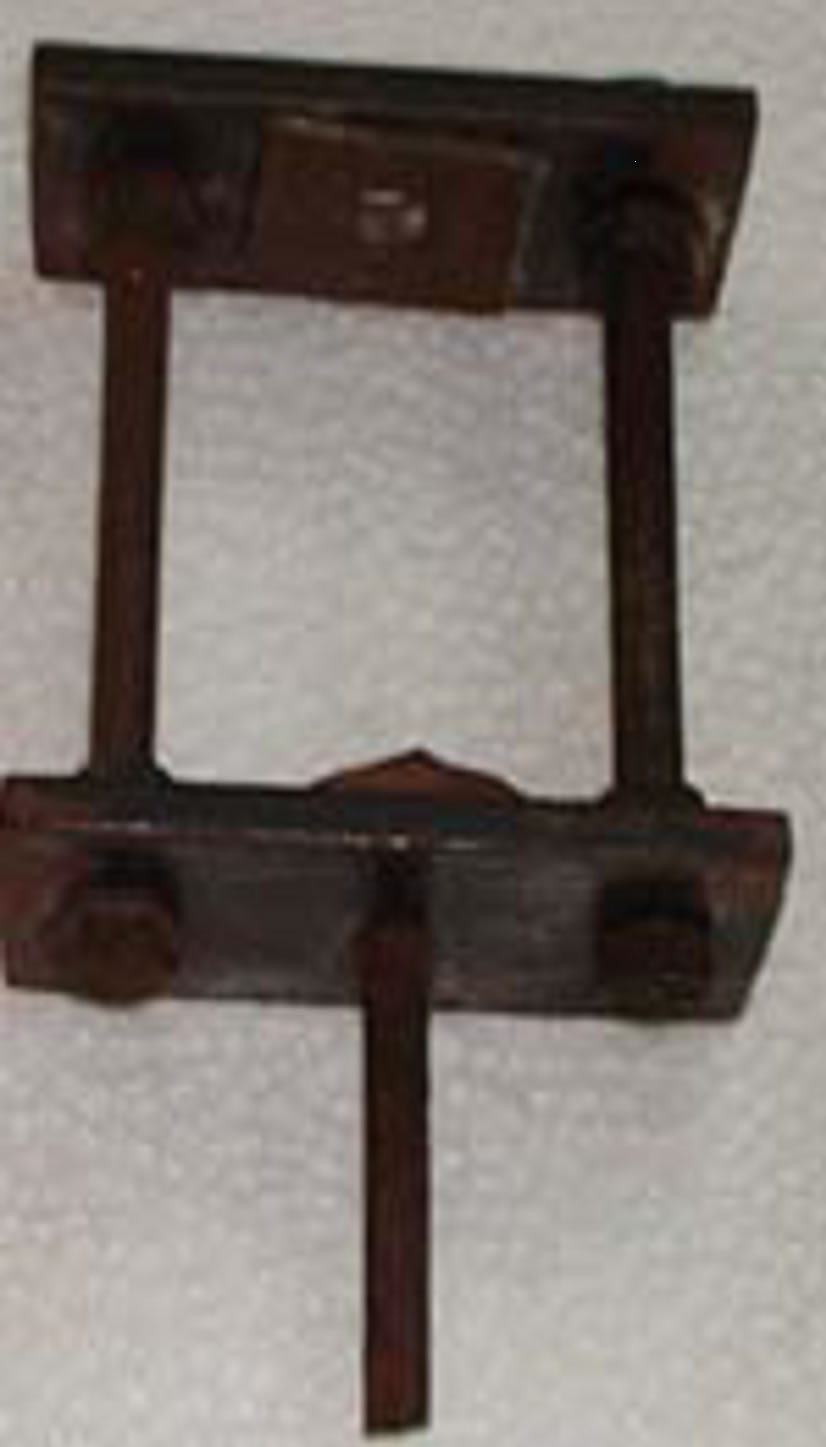
Figure 1. Jet used for test.
alumina grits having a grit size of 60. The stand-off distance in shot blasting is kept between 120 - 150 mm. The average roughness of the substrates is 6.8 µm. The grit blasted specimens are cleaned in an ultrasonic cleaning unit for 10 minutes. Spraying is carried out immediately after cleaning.
In this study red mud, fly ash, carbon and aluminum powders are used as raw materials for coating on the substrates. The different combination of these materials chosen for spraying are listed in Table 1.
The size range of all particles used is from 80 - 100 micron.
A conventional atmospheric plasma spraying set up is used. The plasma input power is varied by controlling the gas flow rate, voltage and the arc current. The powder feed rate is kept constant at 10 gm/min, using a turntable type volumetric powder feeder. The powders are deposited at spraying angle of 90˚. The operation parameters during coating deposition process are listed in Table 2.
3. RESULTS & DISCUSSION
3.1. Analysis of Coating Surfaces
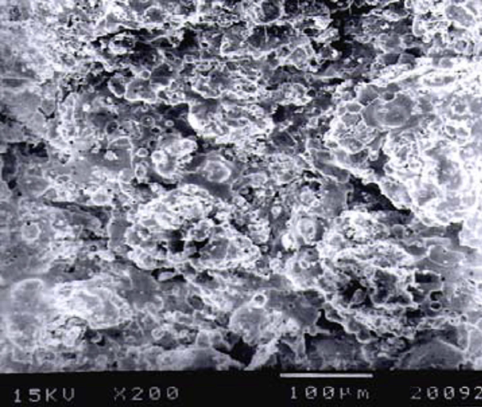
The coating surface interface adhesions depend on the coating morphology and interparticle bonding of the sprayed powders. In case of red mud coatings the surface morphologies of the coatings deposited at different operating power levels are shown in Figures 2(a)-(d) respectively. For the coating made at lowest power level, i.e. at 6 KW, the morphology (Figure 2(a)) shows uniform distribution of molten or semi molten particles. Little
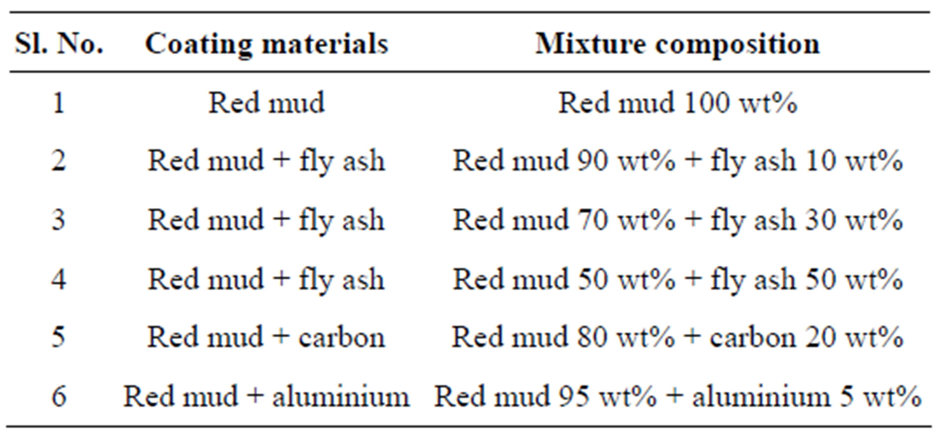
Table 1. Powders used for coating deposition.
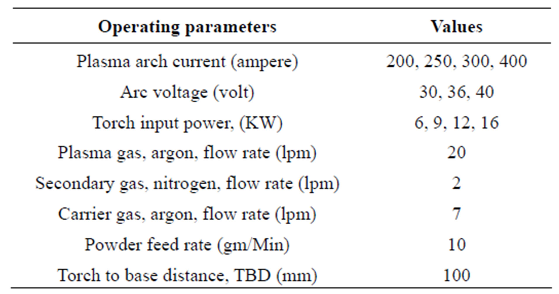
Table 2. Operating parameters during coating deposition.
 (a)
(a) (b)
(b)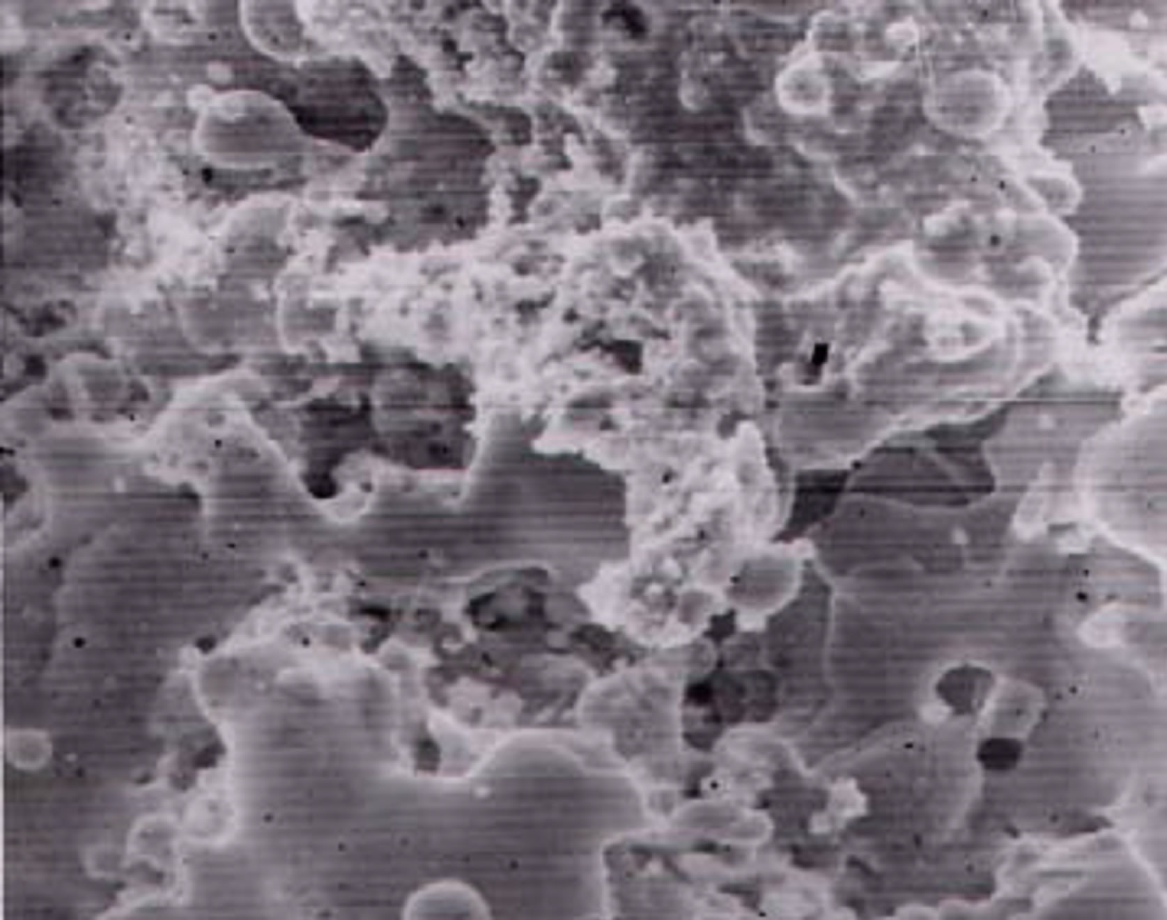 (c)
(c) (d)
(d)
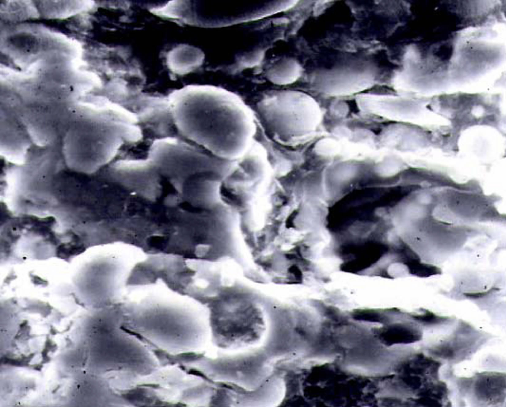
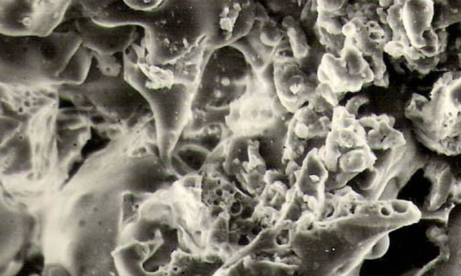
Figure 2. Surface morphology (SEM micrograph) of red mud coatings deposited at (a) 6 KW; (b) 9 KW; (c) 12 KW and (d) 16 KW operating power level.
amount of cavitations is observed, other than some fine pores found on the grains, which may have originated during solidification of particles from molten state. Some amorphous and partially molten particles are also seen. The coating made at a higher power level, i.e., 9 KW (Figure 2(b)) bears a different morphology. A large number of globular particles and some flattened regions, indicative of proper melting of the particles of the sprayed powder are seen. The grains are mostly equal axed type with little boundary mismatch between them. Amount of cavitations is less than that in the previous case. However, some cavity regions are seen along inter particle and intergrain boundaries.
Coating deposited at further higher power level, i.e., at 12 KW (Figure 2(c)) bears a still different morphology. Larger portions of the coatings exhibit flattened regions, which might have been formed during solidification of molten particles that have fused together, in lumps. Inter granular porosity is also noticed at triple grain boundary regions. No cavitation is observed at inter grain boundary. For the coatings deposited at further higher power level, i.e., at 16 KW (the highest power level under this investigation), the surface morphology (Figure 2(d)) is completely different. A large number of spheroidal particles of different diameters are seen, which might have been formed due to breaking or fragmentation of bigger particles and have melted during in flight traverse through the plasma jet. Amount of cavitation is more than those seen in all the previous conditions. This might be the cause for the improper particle to particle bonding and poor stacking to the substrate, which have resulted in lower interface bond strength.
The surface morphology of the red mud + fly ash coatings (with 30% fly ash) is shown in Figures 3(a)-(d). Coating made at lowest power level, i.e., at 6 KW (Figure 3(a)) shows spheroidal and elongated particle or grains with good inter particle bonding. At some region grains have fused together to form a splat or flattened area. Some cavities that are clearly visible might have been originated at inter particle boundary regions. With further increase in power level of coating deposition i.e. at 9 KW and 12 KW (Figures 3(b) and (c)); there
 (a)
(a)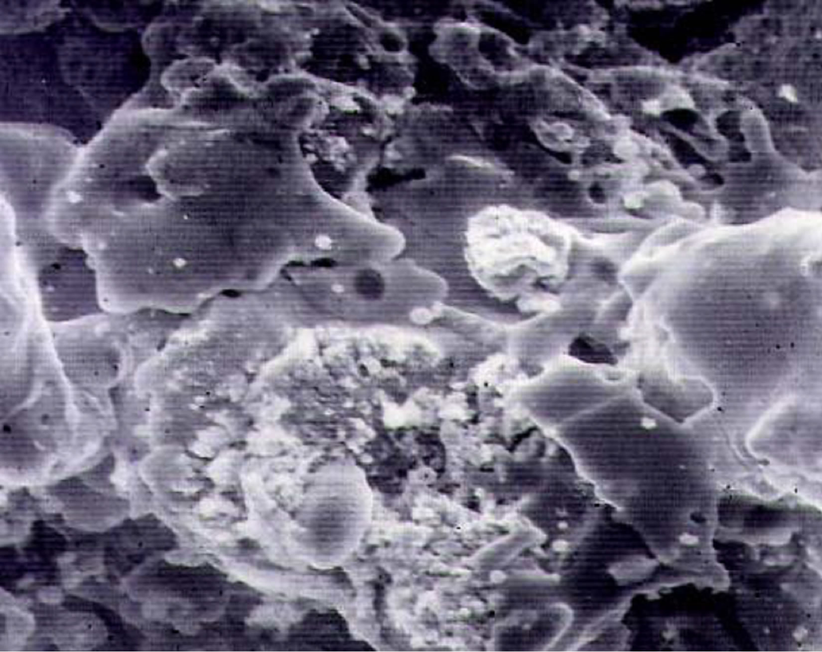 (b)
(b)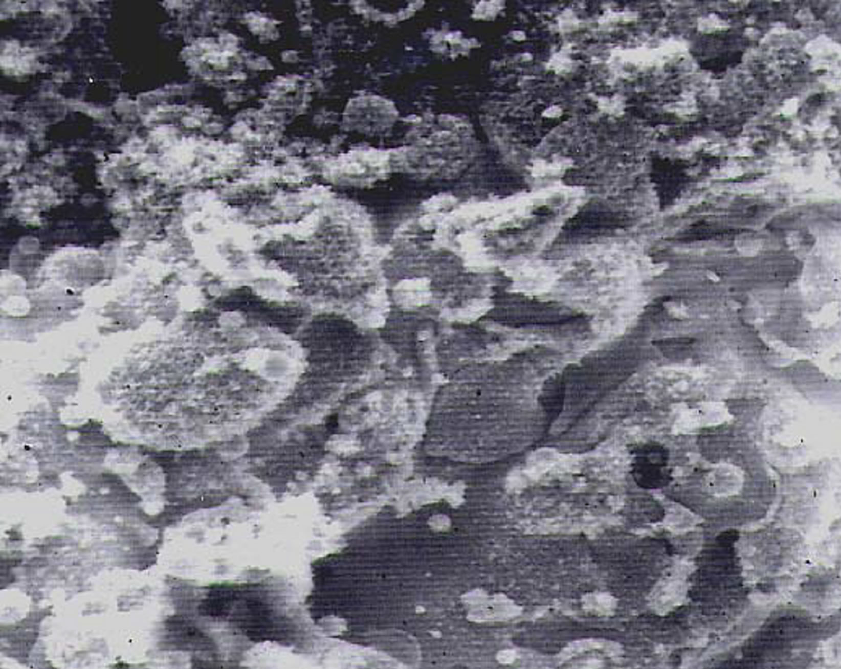 (c)
(c)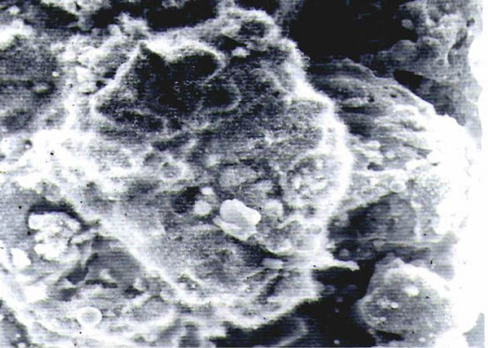 (d)
(d)
Figure 3. Surface morphology of red mud + 30% fly ash coatings deposited at (a) 6 KW; (b) 9 KW; (c) 12 KW and (d) 16 KW operating power level.
is a drastic reduction in cavity regions which might be due to solidification of molten or semi molten particles forming flattened regions and reducing inter particle mismatch or porosity.
For the coating deposited at highest power level, i.e., at 16 KW (Figure 3(d)), the amount of porosity appears to have increased again. Particles are fused together to form larger chunks with cavities at the inter boundary regions. Some smaller particles are also noticed, which might have resulted due to fragmentation of bigger ones during spraying.
The results obtained from the measurement of interface bond strength of various coatings reveal that, with addition of fly ash, there is an improvement in adhesion strength of red mud coatings; with the maximum bond strength of ≈13.78 MPa obtained for coatings deposited at 12 KW. Hence the surface morphology of the coatings deposited at 12 KW for different feed materials (i.e., red mud + 50% fly ash, red mud + carbon, red mud +5% aluminum) are compared in Figures 4(a)-(c) respectively. For the coatings made with 50% fly ash addition shows flattened regions (of particles or grains) and with some cavities at inter particle boundary space, which might have been caused due to improper selection of powder feed rate. There can also be possibilities (for such cavity regions) for the molten particles to coagulate together before solidification and reducing the surface area due to surface tension force and have flattened while impacting the substrate, resulting formation of inter particle boundary cavitation. When carbon is mixed with red mud for coating deposition (Figure 4(b)), it shows a different structure. Most of the particles have fused to form elongated shaped structures. Flattened areas are clearly visible, but with a good amount of cavities at inter particle boundaries. When aluminum is added to red mud for coating deposition, as shown in Figure 4(c), a great change in the coatingmorphology is found. Most of the grains are equalaxed type and are flattened with better inter particle adhesion. This might have been originated from melting of aluminum powders during spraying (which remain molten till reaching the substrate). Also addition of aluminum to red mud might have helped in joining of molten and semi molten particles during in flight traverse as aluminum would remain in molten state
 (a)
(a) (b)
(b)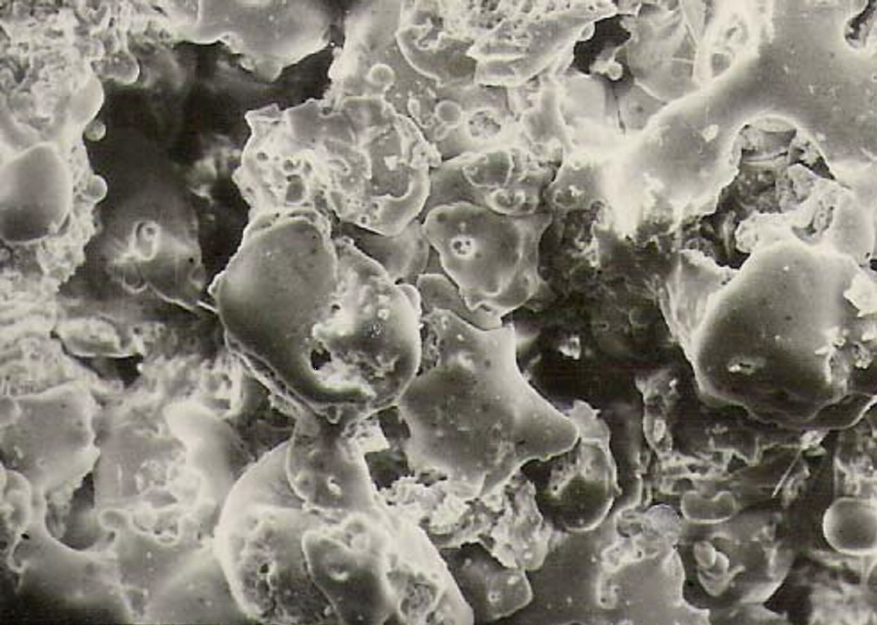 (c)
(c)
Figure 4. Surface morphology of coatings (a) red mud + fly ash; (b) red mud + carbon; and (c) red mud + aluminum deposited at 12 KW power level.
for a longer time even after leaving the plasma jet. In this case, amount of cavitation is also less, as compared to the cases with feed materials.
3.2. Analysis of Erosion Wear behavior
Figure 5 presents a typical erosion curve for different red mud coatings at 90˚ angle of impact. It is seen that initially the cumulative coating mass loss increases rapidly and later on becomes almost stagnant. This trend is observed in case of all the four coatings (made with the plasma torch operating at input power levels of 6, 9, 12 and 16 KW respectively Figures 6-8 show the erosion wear rates of these coatings for 30˚, 60˚ and 90˚ impact angles respectively. Similarly, erosion rates of coatings made with red mud premixed with 30% fly ash and with 5% aluminum are presented in Figures 9 and 10 respectively. It is evident from these figures that a transient regime in the erosion process exists, during which the incremental erosion rate decreases monotonically down to a constant steady state value. This constant value is referred to as the steady state erosion rate.
The decrease in the wear rate of various plasma sprayed coatings with erosion time (or erodent dose) has been reported and the incremental erosion rate curves start with a high rate at the first measurable amount of erosion and then decreases to a much lower steady state value.
This trend is found in case of all coatings subjected to erosion test at various impact angles. This can be attributed to the fact that the fine protrusions on the coating parts are relatively loose and can be removed with less energy than what would be necessary to remove a similar part from the bulk of the coating. Consequently, the initial wear rate is high. With increasing exposure time the rate of wear starts decreasing and in the transient erosion regime, a sharp drop in the wear rate is obtained. As the coating surface gradually gets smoothened, the rate of erosion becomes steady.
Figure 11 illustrates the effect of impact angle on the mass loss of various coatings subjected to solid particle
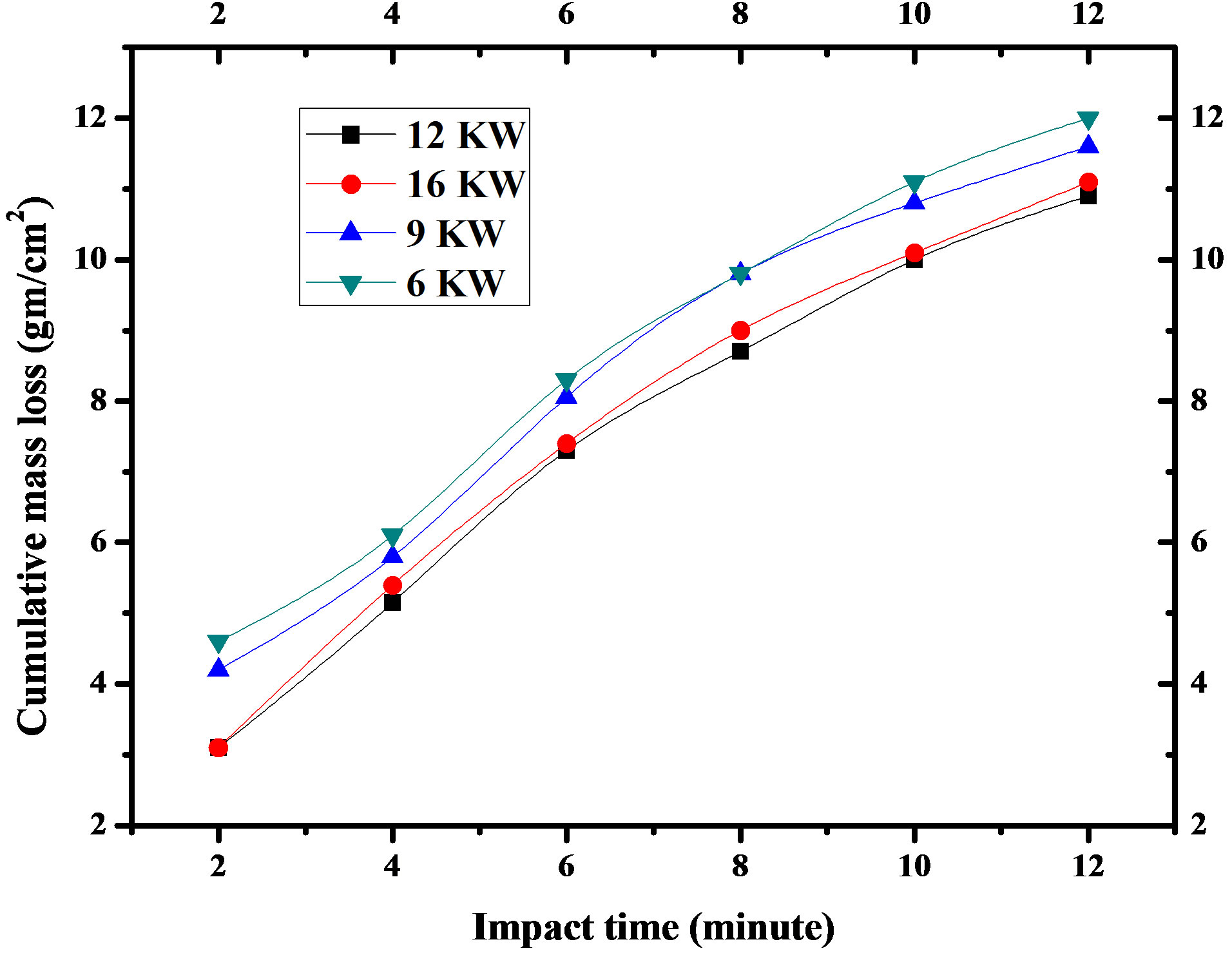
Figure 5. Cumulative mass loss of red mud coatings made at different operating power levels with 90˚ angle of impact.
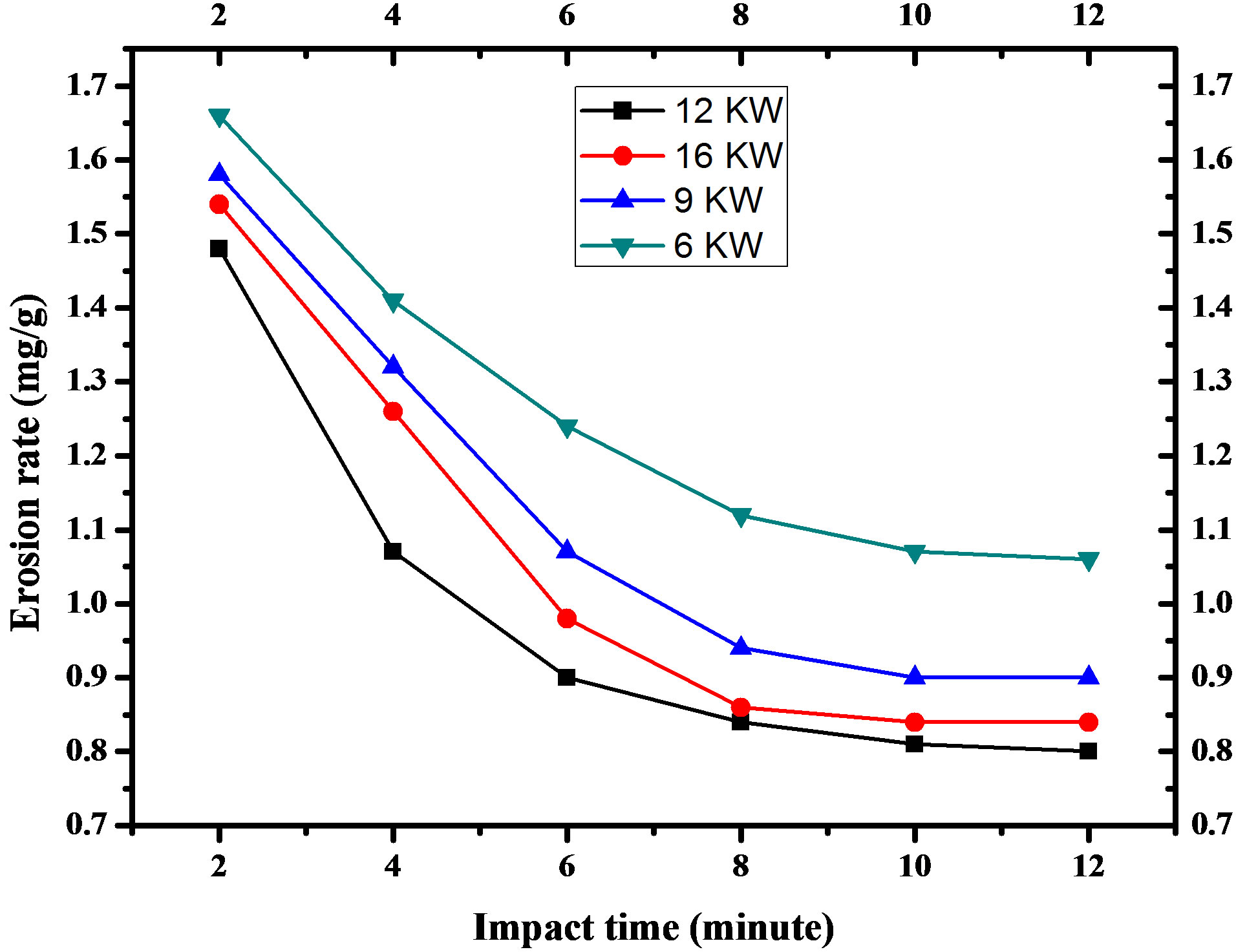
Figure 6. For red mud at 30˚ angle of impact.
erosion. The erosion results for coatings of different materials deposited at 12 KW operating power of the plasma torch at impact angles of 30, 60 and 90 degrees are shown. Mass loss is measured after the samples are exposed to the erodent stream for 12 minutes. It is seen from the graph that irrespective of the feed material, the
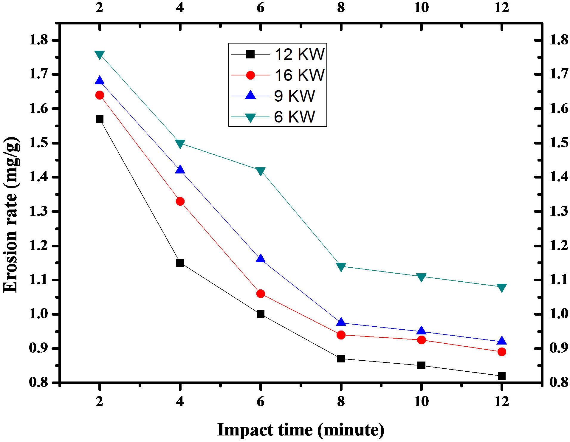
Figure 7. For red mud at 60˚ angle of impact.
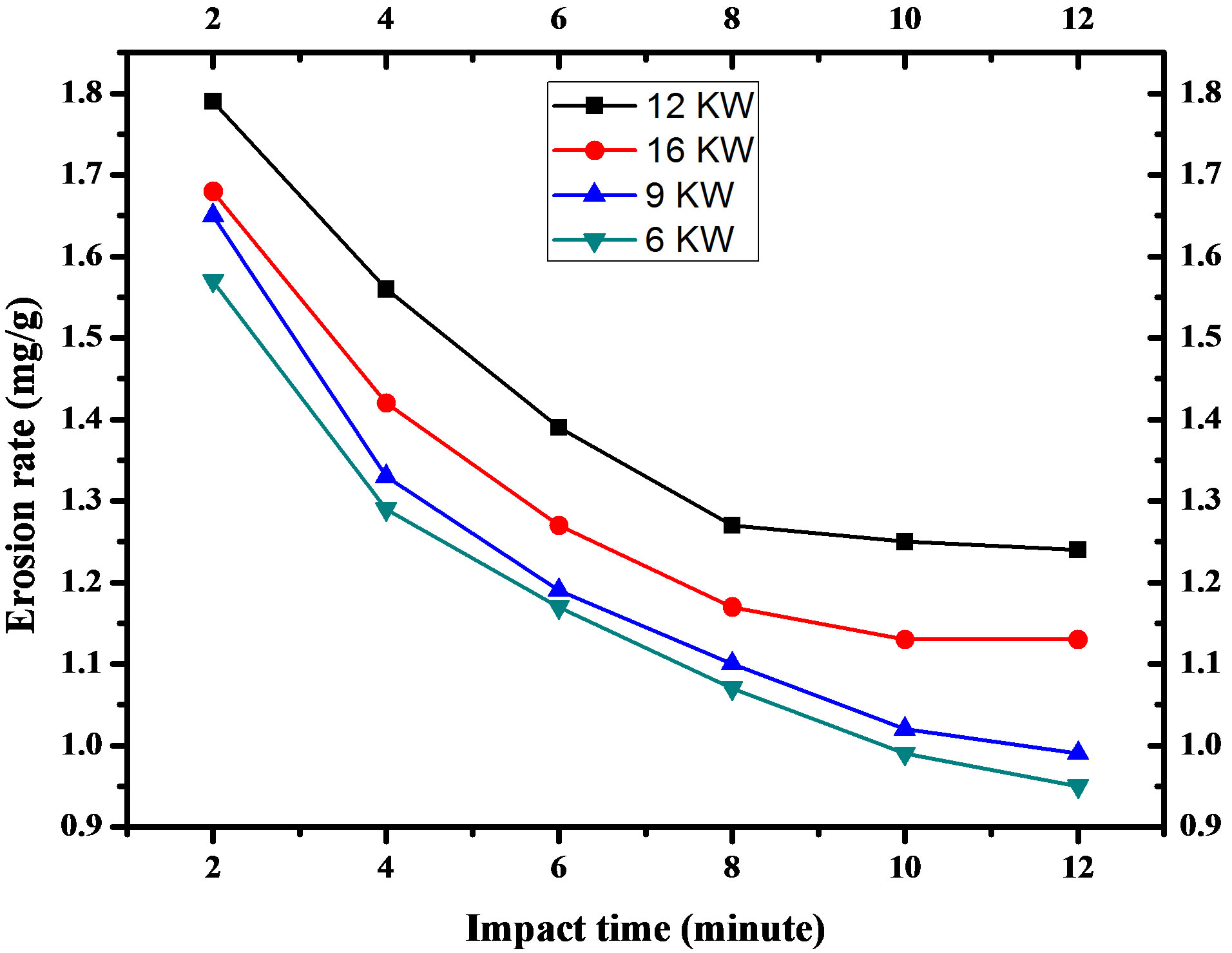
Figure 8. For red mud at 90˚ angle of impact.
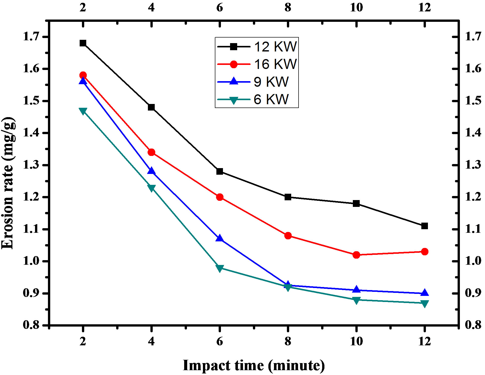
Figure 9. Variation of erosion wear rate of red mud (70%) and fly ash (30%) coatings deposited at 6, 9, 12 and 16 KW With time for 90˚ angle of impact.
erosion mass loss is higher at larger angle of impact and
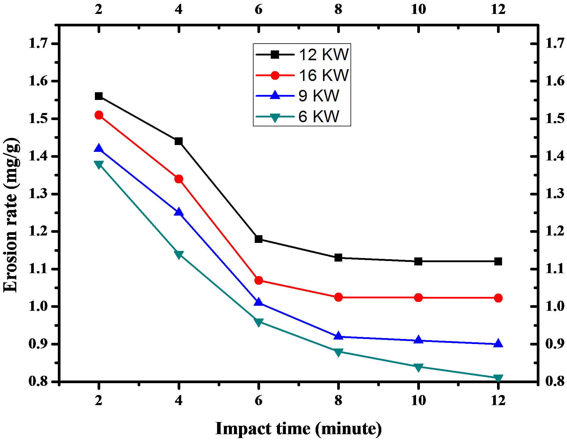
Figure 10. Variation of erosion wear rate of red mud (95%) and aluminum (5%) coatings deposited at 6, 9, 12 and 16 KW With time for 90˚ angle of impact.
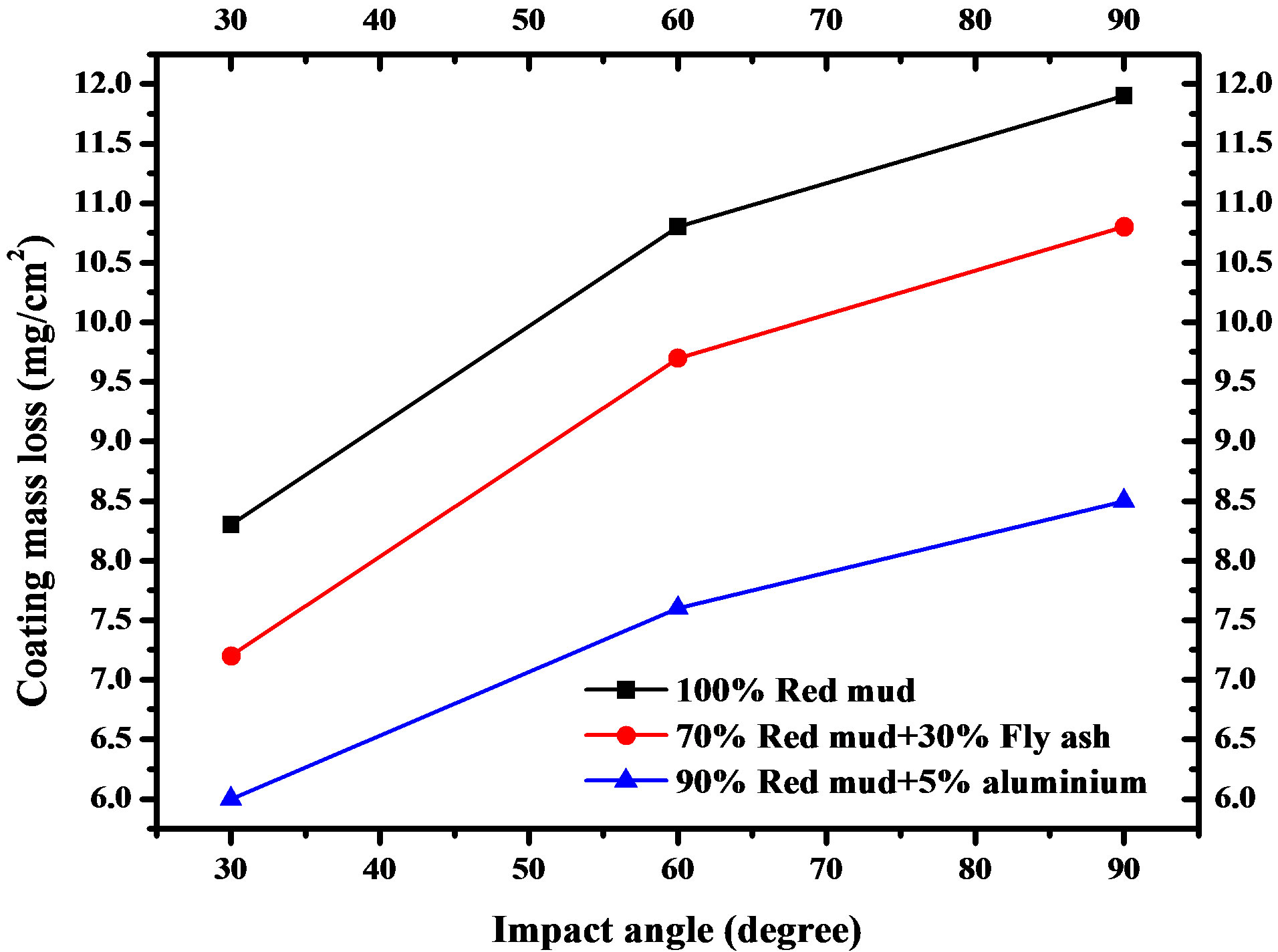
Figure 11. Variation of cumulative mass loss of different coatings made at 12 KW with angle of impact for impact time 12 minutes.
the maximum erosion takes place at impact angle of 90˚.
The results obtained in the present work show that for 90˚ impact angle, red mud coating loses 11.96 mg per every cm2 area in 12 minutes while the mass loss is only 8.34 mg/cm2 in case of impact angle 30˚. These values are 10.85 mg/cm2 and 7.21 mg/cm2 for red mud + fly ash coating, 8.89 mg/cm2 and 5.98 mg/cm2 for red mud + aluminum coating respectively. This variation of erosion wear loss confirms that the angle at which the stream of solid particles impinges the coating surface influences the rate at which the material is removed. It further suggests that, this dependency is also influenced by the nature of the coating material. The angle of impact determines the relative magnitude of the two components of the impact velocity namely, the component normal to the surface and parallel to the surface. The normal component will determine how long the impact will last (i.e., contact time) and the load. The product of this contact time and the tangential (parallel) velocity component determines the amount of sliding that takes place. The tangential velocity component also provides a shear loading to the surface, which is in addition to the normal load that the normal velocity component causes. Hence as this angle changes the amount of sliding that takes place also changes as does the nature and magnitude of the stress system. Both of these aspects influence the way a coating wears. These changes imply that different types of material would exhibit different angular dependency.
4. CONCLUSION
It is concluded from the present study that red mud the waste generated from alumina plants is eminently coat able on metal substrates employing thermal plasma spraying technique. Coatings made with red mud posses desirable coating characteristics and have ample resistance to wear. Therefore, red mud can be a substitute for conventional plasma spayed ceramic coatings. Coating morphology for red mud is largely affected by the torch input power. During plasma spraying of red mud, phase transformation and inter oxide formation are observed. The present work leaves a wide scope for future investigators to explore many other aspects of red mud coatings. Further investigation can be done to study the effect of operating power level of the plasma torch on coating adhesion strength, deposition efficiency and coating hardness. Evaluation of thermal stability of these coatings may be done to find high temperature applications. Sliding wear behavior under different operating condition may be investigated to identify suitable application areas. Post heat treatment of these coatings may also be done to study further improvement in coating qualities and properties.
REFERENCES
- Gieger, G. (1992) Ceramics coatings enhance material performance. American Ceramic Society Bullet, 71, 1470- 1481.
- Mendelson, M.I. (1978) Theoritical evaluation of wear in plasma-sprayed TiO2 against grey iron. Wear, 50, 71-83. HUdoi:10.1016/0043-1648(78)90246-6U
- Fernandez, J.E., Wang, Y., Tucho, R., Martin-Luengo, M.A., Gancedo, R. and Ricon, A. (1996) Friction and wear behavior of plasma sprayed Cr2O3 coatings against steel in a wide range of sliding velocities and normal loads. Tribology International, 29, 333-343. HUdoi:10.1016/0301-679X(96)00061-8U
- Wei, J. and Xue, Q. (1996) The friction and wear properties of Cr2O3 coating with aqueous lubrication. Wear, 199, 157-159. HUdoi:10.1016/0043-1648(95)06846-5U
- Mohanty, M., Smith, R.W., DeMonte, M., Celis, J.P. and Lugscheider, E. (1996) Sliding wear behavior of thermally sprayed 75/25 Cr2C3/NiCr wear resistant coatings. Wear, 198, 251-266. HUdoi:10.1016/0043-1648(96)06983-9U
- Asanabe, S. (1987) Applications of ceramics for tribological components. Tribology International, 20, 355-364. HUdoi:10.1016/0301-679X(87)90064-8U
- Heiman, R.B. (1996) Plasma-spray coating: Principle and application. Wiley-VCH, Weinheim.
- Budinski, K.G. (1988) Surface engineering for wear resistance. Prentice Hall, New Jersey.
- Stratford, K.N. (1984) Coatings and surface treatments for corrosion and wear resistance. Corrosion Engineering, Science and Technology, Birmingham.
- Li, J.F., Ding, C.X., Huang, J.Q. and Zahang, P.Y. (1997) Wear mechanism of plasma sprayed Cr3C2-NiCr against TiO2 coating. Wear, 211, 177-184. HUdoi:10.1016/S0043-1648(97)00109-9U
- Angle, P.A. (1976) Impact wear of materials. Elsevier, New York.
- Tilly, G.P. (1979) Erosion caused by impact of solid particles. In: Scott, D., Ed., Treatise on Materials Science and Technology, Vol. 13: Wear. Academic Press, New York, 287-320.
- Field, J.E., Gorham, D.A., Hagan, J.T., Matthewson, M.J., Swain, M.V. and van der Zwaag, S. (1979) 5th international conference on erosion by liquid and solid impact. Cavendish Laboratory, University of Cambridge, Cambridge.
- Field, J.E., Gorham, D.A., Hagan, J.T., Matthewson, M.J., Swain, M.V. and van der Zwaag, S. (1987) 7th international conference on erosion by liquid and solid impact. Cavendish Laboratory, University of Cambridge, Cambridge.
- Evans, A.G. (1979) Impact damage mechanism: Solid projectile. In: Preece, C.M., Ed., Treatise on Materials Science and Technology, Vol. 16: Materials Erosion, Academic Press, New York, 1-67.