Engineering
Vol.10 No.06(2018), Article ID:85676,12 pages
10.4236/eng.2018.106025
Designing a New Design of a Loading Cylinder for Pneumomechanical Spinning Machines
Mirzaev Otabek Abdukarimovich1, Akhmedov Kamol Ibragimovich1, Sarimsakov Olimjon Sharipjanovich2
1Tashkent Institute Textile and Light Industry, Tashkent, Uzbekistan
2Namangan Institute of Engineering and Technology, Namangan, Uzbekistan

Copyright © 2018 by authors and Scientific Research Publishing Inc.
This work is licensed under the Creative Commons Attribution International License (CC BY 4.0).
http://creativecommons.org/licenses/by/4.0/


Received: February 18, 2018; Accepted: June 26, 2018; Published: June 29, 2018
ABSTRACT
The article explores the issue of designing a new design of a loading cylinder with a casing filled with vulcanized rubber for pneumomechanical spinning machines. The theoretical calculation of the deformed state of a cylindrical shell filled with vulcanized rubber is given. Deflections and stresses in the rubber layer are determined, which we use approximately for the Ritz methods. The theory of the radial and axial moving rubber layer was analyzed. The specific energy of deformation of a cylindrical layer of a compound cylinder is determined. The statics of the case and the loading cylinder of spinning machines are thoroughly studied.
Keywords:
Rubber, Moving, Euler Equalization, Ritz Method, Radial Directions, Cylinder, Young’s Module

1. Study of the Characteristic of Stretching Unfilled Rubber
As a rule, rubber differs from other structural materials by its ability to be stretch. Figure 1 shows the stretching curve of a specimen filled with rubber from natural rubber obtained in [1] [2] [3] [4] from which it can be seen that the sample can be stretched without breaking up to a tenfold initial length. In this case, the sample can be stretched almost to destruction without significant residual deformations. The experiments show that when the rubber is deformed its volume remains practically unchanged. This regularity is confirmed by the graphs shown in Figure 2, obtained by experiments in [1] [5] [6] [7] .
It can be seen from the curves that before deformation, the change in volume is within the limits of the accuracy of the measurements and
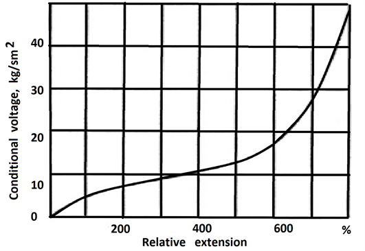
Figure 1. Characteristic of the stretching of unfilled rubber.
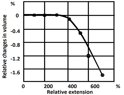
Figure 2. Changes in the volume of stretching rubber out natural rubber according to Holtaand Makferson.
for large deformations the volume of the sample decreases. In connection with this, the volume of rubber can be neglected for small values of its strain. Thus, for small deformations, according to Hooke’s law for linearly elastic materials, the Poisson’s ratio will be , and Young’s module can be adopted (G-shear modulus of rubber material). In this case, the mechanical property of the rubber material is determined only through the Young’s modulus E or shear modulus G. If we denote by , , -axial, , and -shear deformations in polar coordinates, then the specific strain energy, taking into account the condition of absence of volume deformation will be [8] .
(1)
The consistency of the volume of rubber must be taken into account not only when calculating, but also when designing rubber products. If this property is not taken into account, then the rigidity of the rubber will be very high, and become inefficient for carrying out the corresponding technological task.
Consider the problem of deformation of a metal cylindrical shell filled with a layer of rubber when it rotates at a constant angular velocity (Figure 3).
Let l denote the length of the cylinder, R0 and R the internal and external radii of the rubber layer, the thickness of the shell through h, the density of the rubber and the shell material, respectively, through and . We establish the origin of coordinates in the middle of the cylinder and direct the 0z axis along the axis of the cylinder. In the absence of external forces in the transverse direction, the 0z axis is the axis of symmetry. We denote by and the radial and axial displacements in an arbitrary section of the layer, the angular displacement will then be zero. To determine the strains and stresses in the rubber layer, we use approximately the Ritz method.
2. Radial and Axial Displacement of the Rubber Layer of the Composite Feed Cylinder
To this end, it is seen that the cross-section of the layer before and after deformation remains flat, and during the deformation process the axial displacement depends only on the coordinate, then the deformations of the cross sections of the layer are determined by the formulas
, , , , (2)
The displacements of the shell along the radius and the axis of rotation, respectively, will be denoted by and . Since the volume of the rubber layer is constant, condition, from which, in view of (2), it follows that
(3)
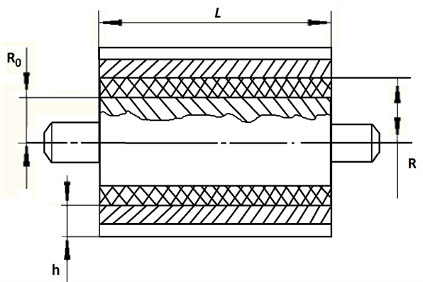
Figure 3. Feed-in cylinder with resilient hobs.
According to the assumed assumptions, it has assumed and integrate equation (3) with condition at , equals
(4)
It has shown and from (4) that it is established the connection between the functions и
(5)
The radial displacement layer and deformation layer with allowance for (4) and (5) are expressed in terms function u by formulas
(6)
, ,
, (7)
The components of the stress tensor will be equal to
, , , (8)
By supplying deformation expressions from (7) in (1), it has determine the specific strain energy of the cylindrical layer
(9)
Integrating over the cross section, we find the strain energy per unit length of the cylindrical layer
(10)
It has proved that the process of shell deformation takes place due to the action of the force of its interaction with a cylindrical layer which magnitude is proportional to the difference between the radial displacements of a shell and a surface of the rubber layer and centrifugal force
(11)
where
k―coefficient of elastic connection between the shell and rubber layer, determined experimentally. The magnitude (per unit length of the cylinder) of these forces is expressed by the formula
The total energy of the system will be
(12)
Taking u variable function, using the variational principle, the Euler equation is
the expression in the last equation is
(13)
where
,
,
Equation (13) contains unknown displacement of the shell for the determination of which, is used in the membrane theory of a cylindrical shell [5] . In the case under consideration, the relationship between deformation and forces are determined by means of formula
, , (14)
where and ―Young’s modulus and Poisson’s ratio for the shell material, force
, ―are expressed by the equations
(15)
(16)
From the Equation (15) it is clearly seen that , ―acting at the edges of shell force. Equations (14), taking into account expressions and are given to species
The last dependences are reduced by the form
, (17)
where , ,
Equation (11) after excluding the displacement of the shell with the aid of (17) reduces to the form
(18)
here ,
The general solution of Equation (18) proves the symmetry form can be represented in the form ( )
(19)
where A―arbitrary constant. The axial displacement of the layer is determined by solving the Equation (5), which proves the symmetry form
3. Graphic Dependencies of Cylinder Rotation on Its Radial and Axial Displacement
To determine an arbitrary constant A it has given two cases of fulfillment of boundary forms in sections
1) Cross-sections free from stress, i.e. . According to formulas (8), it fallows at
The solution of Equation (18) which proves these forms
,
The radial and axial displacements of the layer along the length of the cylinder according to formulas (6) and (19) are distributed according to the laws
(20)
(21)
It follows from formula (2) that, due to the assumed incompressibility condition, the axial movement of the rubber does not depend on the radial coordinate.
Figure 4 shows the distribution curves of the radial displacement of the layer for two values of the cylinder rotation at different distances from the axis of the cylinder. It is seen that as the distance and displacement increase. A zone with a constant value of displacement is formed along the cylinder.
Figure 5 shows the distribution of the axial displacement of the layer along the axis of the cylinder for two values of the cylinder’s rotation: the graph on the left side with the rotation speed of the cylinder n = 8.5 turn/of minutes, and on the
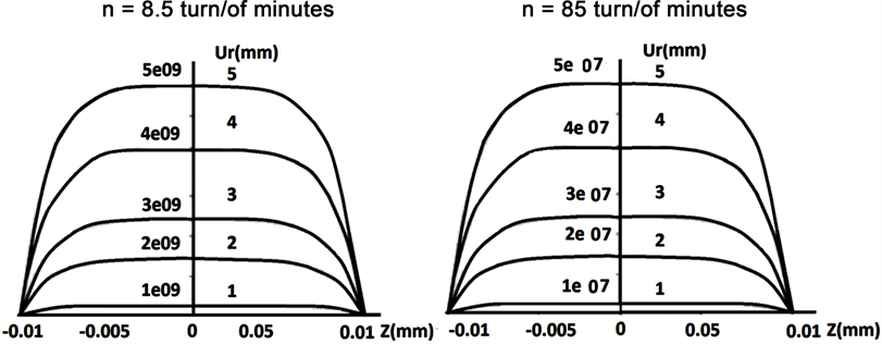
Figure 4. Distribution of radial displacement of the layer along the axis of the cylinder for two values of the cylinder rotation n at various distances from its center : 1― , 2― , 3― , 4― , 5― .
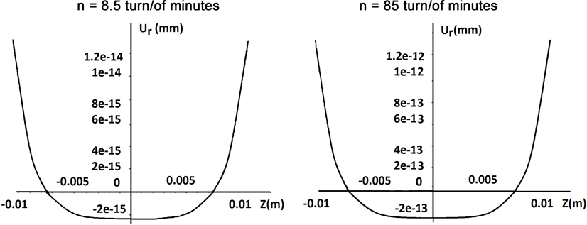
Figure 5. Distribution of the axial displacement of the layer along the axis of the cylinder for two values of the cylinder rotation n.
right―n = 85 turn/of minutes. The displacement has a parabolic character of the change, that is, at the center of the axis the displacement has a minimum value and with an increase in the coordinate the displacement sharply increases in accordance with the power law. In this case, a large number of revolutions lead to a smaller displacement.
Figure 6 and Figure 7 show similar curves for the distribution of the axial displacement of the rubber layer (Figure 6) for two values of the cylinder rotation. From the analysis of the curves it follows that the radial and axial displacements of the rubber layer for the case under consideration have the same order and practically insignificant, therefore their deformation can be neglected.
2) The ends of the cylindrical rubber layer (section ) stationary in the longitudinal direction, which corresponds to the contact of the end of the cylindrical layer with a stationary smooth disk (flange)
in (at)
The solution of Equation (19) with respect to , satisfying these conditions can be represented in the form
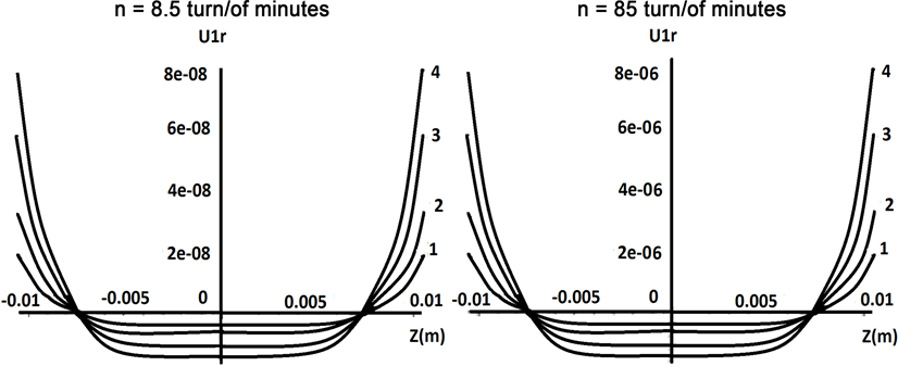
Figure 6. The distribution of the radial displacement of the layer along the axis of the cylinder for two values of the cylinder rotation n at various distances from its center : 1― , 2― , 3― , 4― , 5― .
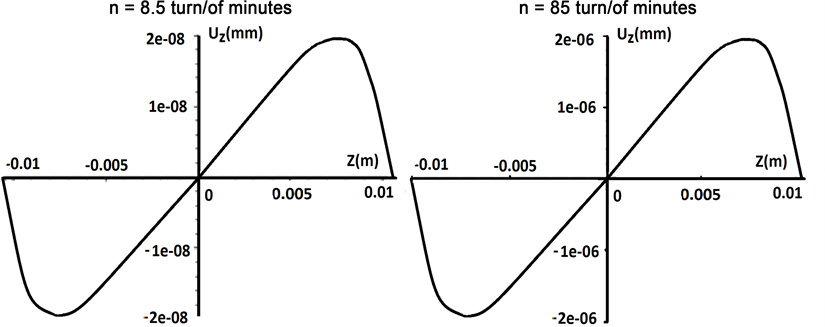
Figure 7. Distribution of the axial displacement of the layer along the axis of the cylinder for two values of the cylinder rotation n.
(22)
The radial displacement of the layer is expressed by formula (4)
(23)
Using the dependences (17), it is determined the radial and derivative with respect to the coordinate of the axial displacement of the shell
(24)
(25)
Let is consider the first case of free ends of a layer from a force where the displacements of the cross sections of the layer are determined by formulas (20) and (21). Movements of the shell are calculated using dependences (24) and (25)
(26)
(27)
From the analysis of the obtained formulas it follows that the axial displacement of the shell turns in the center due to the observance of the symmetry condition and assumes maximum values (with opposite signs) at the edges of the shell. Two types of fulfillment of the boundary condition at the edges of the shell in the axial direction.
1) The shell edges in the axial direction are free, then it should be assumed
Then in the formulas (20) and (21) it is necessary to assume .
The shell interpolations are calculated from formulas
(28)
(29)
Curves for changes in the radial displacement of the shell are shown in Figure 8. It is evident that, due to the high rigidity of its material, the movement of the shell at the contact boundary is much lower than the displacement of the rubber layer.
Analogous curves for the distribution of the axial displacement of the shell are shown in Figure 9. It is evident that the nature of the distribution of the axial displacements of rubber layer and shell differ significantly from each other. In this case, the movement of the shell by an order of magnitude (102 - 103 times) less than moving the layer.
2) The edges of shell in the axial direction are fixed. Then setting in formula (27) and taking expression , it is formulated an equation for determining the quantity
From this equation, it follows the value
(30)
where , it can be seen that
Since the edges of the shell in this case under consideration are in a compressed state, it is necessary to require that condition , from where follows
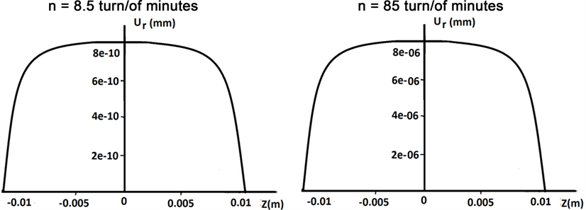
Figure 8. The distribution of the radial displacement of the shell along the axis of the cylinder for two values of the cylinder rotation n.
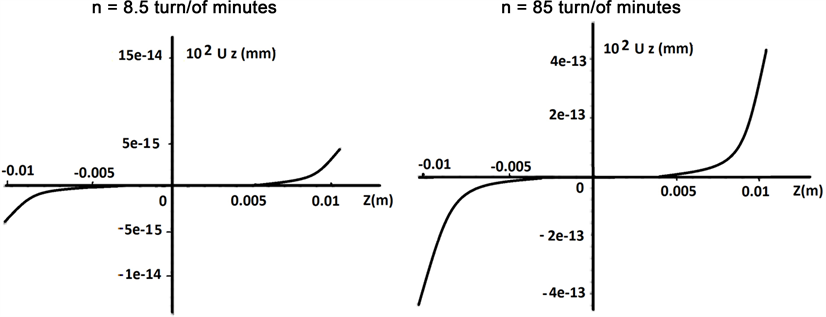
Figure 9. Distribution of axial movement of the shell along the axis of the cylinder for two values of the cylinder rotation n.
. (31)
Inequality (31) in the determines the radius values R and coefficient k, where the shell will be in a compressed state. With values , lying on the curve , loss of stability of the shell occurs.
For the selected values of the task parameters, the value has order .
Therefore, in this case the second case is practically not realized.
In the second case, when boundary conditions are satisfied at the ends of the rubber layer, the movement is determined by formulas
(32)
(33)
It can be seen from formula (33) that the axial movement of the shell at the edges becomes zero only in the absence of an axial force . This case can be realized by contacting the ends of the rubber layer with a fixed flange, and the edges of the shell remain free. In this case, in the formulas (22), (23), (32) and (33) it is necessary to assume .
Figure 10 and Figure 11 show the distribution of radial and axial displacements of the shell for two values of the angular velocity rotation of the cylinder in rpm.
When the axial displacement edges of shell do not vanish. It is possible that there is no movement of shell in the radial direction. Assuming in formula (28) , we find the value of the axial force in which the shell
will not mix in the radial direction
From this equality, it follows the quantity:
Where
4. Conclusions
1) Theoretical distributions of the radial moving of layer have being studied for two values of turn cylinder in different distances from the axis to cylinder.
2) It is possible to improve process parameters feed in pneumomechanic spinning
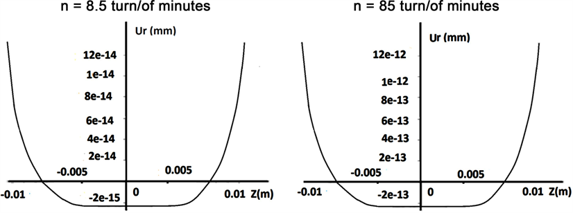
Figure 10. The distribution of the radial displacement of the shell along the axis of the cylinder for two values of the cylinder rotation n.
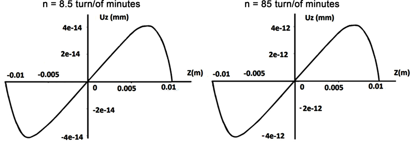
Figure 11. The distribution of the axial displacement of the shell along the axis of the cylinder for two values of the cylinder rotation n.
machines.
3) The given diminishes such as damages of fibers in are feeding zone.
4) The graphs of the distribution for the radial displacement of the layer for two values of cylinder rotation with different distances from the axis to the cylinder are presented.
Cite this paper
Abdukarimovich, M.O., Ibragimovich, A.K. and Sharipjanovich, S.O. (2018) Designing a New Design of a Loading Cylinder for Pneumomechanical Spinning Machines. Engineering, 10, 345-356. https://doi.org/10.4236/eng.2018.106025
References
- 1. Ponomarev, S.D., Biderman, V.L, Likharev, K.K., et al. (2014) Calculations on durability in Mechanical Engineering. State Scientific and Technical Publishing Houses of Machine-Building Literature, Moscow.
- 2. Muradov, R. (2015) Bases of Increase of Efficiency of the Device for Pneumatic Transportation of Cotton. Monograph, Namangan.
- 3. Skalak, R. (1957) Longitudinal Impact of a Semi-Infinite Circular Elastic Bar. Journal of Applied Mechanics, 79, 59-64.
- 4. Sneddon, I.N. and Tait, R.J. (1963) The Effect of Penny-Shaped Crack on the Distribution of Stress in a Long Circular Cylinder. International Journal of Engineering Science, 1, 391-409. https://doi.org/10.1016/0020-7225(63)90016-8
- 5. Flugge, V. (2014) Statics and Dynamics of Shells. Springer, Berlin.
- 6. Hobson, G. and Born, J.S. (2014) Tables of Self-Equilibrating Function. J. Math. and phys., Liberek, Chehiya.
- 7. Horvay, G. (1953) The End Problem of Rectanqular Strip. Journal of Applied Mechanics, 20, 87-94.
- 8. Zhumaniyazov, K.Zh., Juraev, A.J., Gafurov, K.G., Matismailov, S.L., Mirzaev, O.A. and Anatoliy, D. (2014) Patent of UZ on Utility Model. FA 00688. “Feeding Cylinder of Spinning Devices” Based on MKK-1.