Engineering
Vol.07 No.05(2015), Article ID:56598,12 pages
10.4236/eng.2015.75022
Modelling Dam Break Evolution over a Wet Bed with Smoothed Particle Hydrodynamics: A Parameter Study
Patrick Jonsson, Pär Jonsén, Patrik Andreasson, T. Staffan Lundström, J. Gunnar I. Hellström
Department of Engineering Sciences and Mathematics, Luleå University of Technology, Luleå, Sweden
Email: patrick.jonsson@ltu.se, par.jonsen@ltu.se, patrik.andreasson@ltu.se, staffan.lundstrom@ltu.se, gunnar.hellstrom@ltu.se
Copyright © 2015 by authors and Scientific Research Publishing Inc.
This work is licensed under the Creative Commons Attribution International License (CC BY).
http://creativecommons.org/licenses/by/4.0/


Received 25 April 2015; accepted 22 May 2015; published 25 May 2015
ABSTRACT
When investigating water flow in spillways and energy dissipation, it is important to know the behavior of the free surfaces. To capture the real dynamic behavior of the free surfaces is therefore crucial when performing simulations. Today, there is a lack in the possibility to model such phenomenon with traditional methods. Hence, this work focuses on a parameter study for one alternative simulation tool available, namely the meshfree, Lagrangian particle method Smoothed Particle Hydrodynamics (SPH). The parameter study includes the choice of equation-of-state (EOS), the artificial viscosity constants, using a dynamic versus a static smoothing length, SPH particle spatial resolution and the finite element method (FEM) mesh scaling of the boundaries. The two dimensional SPHERIC Benchmark test case of dam break evolution over a wet bed was used for comparison and validation. The numerical results generally showed a tendency of the wave front to be ahead of the experimental results, i.e. to have a greater wave front velocity. The choice of EOS, FEM mesh scaling as well as using a dynamic or a static smoothing length showed little or no significant effect on the outcome, though the SPH particle resolution and the choice of artificial viscosity constants had a major impact. A high particle resolution increased the number of flow features resolved for both choices of artificial viscosity constants, but at the expense of increasing the mean error. Furthermore, setting the artificial viscosity constants equal to unity for the coarser cases resulted in a highly viscous and unphysical solution, and thus the relation between the artificial viscosity constants and the particle resolution and its impact on the behavior of the fluid needed to be further investigated.
Keywords:
SPH, Dam Break, Smoothed Particle Hydrodynamics

1. Introduction
In Sweden, hydropower plays a significant role in the supply of energy and it generates roughly 45% (66.0 TWh in 2011) of the total electricity power production [1] . The first larger hydropower plant in Sweden commenced its operation for almost 100 years ago and the latest was put into service in the 1970s. Hence, most of the hydropower plants in Sweden are old, which has initiated a number of projects on refurbishments. Due to the deregulated energy market, hydropower plants are more and more run at off design conditions. Consequently, to have an optimal hydropower that, for instance, can run at the best efficiency point when the winnings are high, the plants must be modernized and adapted to the energy market. Other key aspects are new requirements on renewable and “green” energy sources. This makes the prospect of redesigning old hydropower stations even higher. Finally, the demand on hydropower as a short term regulating source is increasing to take care of more frequent and larger fluctuations in the energy system, mostly due to the on-going expansion of wind power. Regarding the Swedish hydropower sector as a whole focus is set on the service and administration as well as refurbishments of existing plants, to meet the new demands. To assess hydraulic properties in these projects, physical scale models are often used. Performance, accuracy and reliability of mathematical models are in these cases considered to be too poor. Hydropower hydraulics is characterized by large scales and flow rates. The geometry is usually partly formed by nature, i.e. to some extent chaotic at a scale of roughness. Furthermore, highly aerated and disturbed free surface flows are frequently encountered, for instance, in spillway channel flows and in energy dissipaters. This constitutes significant mathematical simulation challenges. Thus, there is a need of computationally robust and reliable numerical methods to handle these fundamentally complex problems. Modelling of highly disturbed aerated free surface flows is complex when grid based method is used [2] . Severe problems with mesh entanglement and determination of the free surface have been encountered [3] . The meshfree, Lagrangian particle based method Smooth Particle Hydrodynamic (SPH), has shown to be a good alternative to grid based methods to overcome such problems [4] [5] . The technique was first proposed independently by [6] [7] in the late seventies to solve astrophysical problems in a three-dimensional open space. Today, the SPH method has been applied to a number of fields and problems [5] and the maturity of the method has increased significantly. Thus, SPH was chosen as the computational method in the present work. In the SPH method, the fluid domain is represented by a set of non-connected particles which possess individual material properties such as density, velocity and pressure [8] . Besides representing the problem domain and acting as information carriers, the particles also act as the computational frame for the field function approximations. As the particles move with the fluid, their material properties change as a function of time and spatial co-ordinate due to interactions with neighboring particles. A major advantage of SPH is that the method is mesh-free, and thus considerable time is saved as compared with methods that need a predefined mesh. However, as the SPH is relatively unexplored as compared with traditional finite volume method (FVM) and finite element method (FEM) methods, there are some areas that still need considerable attention. For instance, wall boundary conditions are generally difficult to set in SPH as they do not appear in a natural way within the SPH formalism. Furthermore, the SPH method is typically slower computational wise since the time step depends on the speed of sound and the explicit integration techniques used. The idealized dam break problem, where a given volume of initially stationary water is released onto a dry channel bed by a sudden removal of a gate, is a well-studied problem (e.g. [9] -[11] ). After the gate has been removed, a negative surge propagates upstream and a dam break wave moves rapidly downstream. If, however, the dam break wave propagates over a wet bed (an initial fluid layer at rest), the flow field will become considerably different, see for instance [12] and [13] . Reference [13] studied the influence of adding a polymer in order to reduce the turbulence drag using a dam break setup. However, clean water test was conducted as well and the experimental results had been used by many authors as a validation test case such as [14] -[16] . The SPH European Research Interest Community (SPHERIC) has adopted the work by [13] , and digitized wave profiles, wave velocity data and snapshots are available at wiki.manchester.ac.uk/spheric. The aim of this paper is to study the effects of several test parameters when applied to the SPHERIC test case based on the work by [13] of dam break evolution over a wet bed. The test parameters are the equation-of-state, the artificial viscosity constants, using a dynamic or a static smoothing length, the SPH particle resolution and the FEM mesh scaling as thin finite shell elements are used as solid wall boundaries.
2. Method
2.1. Governing Equations
The superscripts α and β are used to denote coordinate directions and the subscripts i and j denotes particle indices. The continuity and momentum equations can be written in the SPH formalism according to,
 (1)
(1)
 (2)
(2)
where  is the density, mj is the particle mass, g is the acceleration due to gravity and xi and
  is the position and velocity vector respectively.
  is the total stress tensor and
 (3)
(3)
In Equation (3), dim is the number of space dimensions and  is the derivative of the function used to define the kernel function W, i.e.
 (4)
(4)
and h is the smoothing length. The commonly used cubic B-spline kernel is obtained by choosing  as,
as,
 (5)
(5)
where C is a constant of normalization defined for one-, two- and three-dimensional spaces as: C1D = 3/2, C2D = 45/14π and C3D = 9/4π. In Equations (3)-(5), R is the normalized distance between two particles, i.e.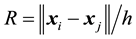 . The total stress tensor
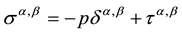
  in the momentum equation (Equation (2)) is made up from two parts, the isotropic pressure p and the deviatoric viscous stress
 , according to
 (6)
(6)
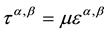
The NULL material model will be applied that defines the deviatoric viscous stress as [17] ,
 (7)
(7)
where  is deviatoric strain rate. By setting the dynamics viscosity
  to zero the total stress tensor reduces to the isotropic pressure which is defined by an equation-of-state (EOS). In literature, several EOSs can be found but in the present work the Gruneisen, Linear Polynomial and the Morris EOS are considered only. The Gruneisen EOS employs the cubic shock velocity-particle velocity and defines the pressure for compressed materials as [17]
 (8)
(8)
and for expanded materials as,
 (9)
(9)
where S1, S2 and S3 are coefficients of the slope of the us-up curve, us and up are the chock and particle velocity respectively. The variable c0 is the intercept of the curve corresponding to the adiabatic speed of sound, γ0 is the Gruneisen gamma,  is the first volume correction to γ0, E0 is the initial internal energy and
  where
where  is the initial density. Properties and constants for water given by [18] are applied, see Table 1. The Linear Polynomial EOS is defined as [17] ,
 (10)
(10)
References [19] and [20] used the following expressions for the constants in Equation (10),
 (11)
(11)
where c0 in Equation (11) is the adibatic speed of sound and , where
  is the initial density. Reference [20] used k = 2 and
 . The Morris EOS [21] defines the pressure as,
 (12)
(12)
which can be obtained by setting the constants  and
and  in the Linear Polynomial EOS. The artificial viscosity proposed by [22] is implemented as,
 (13)
(13)
where
 (14)
(14)
q1 and q2 are constants and  and
and  are the distance and velocity vector, respectively. Over bars denote average values. If the smoothing length h is dynamic an average value is used, i.e.
 . The
. The  is used to avoid the denominator to go to zero. According to [22] , the linear term associated with q1in the artificial viscosity expression produces both bulk and shear viscosity. The second quadratic term is incorporated to handle high Mach number shocks and is intended to suppress particle penetrations [22] and [8] . Furthermore, the values of the constants q1 and q2 are according to [14] problem dependent. In literature, many authors suggest setting q2 to zero and q1 between 0.01 and 0.1 [23] and [24] . However, [8] states that the values of q1 and q2 are usually set around unity. The impact of the choice of the constants will be another parameter to be studied in the present work. With the reduction of the total stress tensor, the inclusion of the artificial viscosity term together with the symmetric properties of the
  term, the momentum equation (Equation (2)) reduces to the familiar expression,
 (15)
(15)
A first order time integration scheme is applied and the time step is determined according to [25] as,

Table 1. Gruneisen EOS properties and constants for water [18] .
 (16)
(16)
where CCFL is the Courant number usually set to unity. The smoothing length h is either static or dynamic. For the dynamic case h is obtained from,
 (17)
(17)
For numerical reasons, a minimum and maximum value is imposed on the smoothing length, i.e. Hminh0 < h < Hmaxh0. In the present study, Hmin and Hmax were set equal to 0.5 and 1.5 respectively while h0 is the initial smoothing length given by , where d0 is the initial distance between particles. The impact on the results from using a static or dynamic smoothing length will also be studied in the current study.
2.2. Boundary Conditions
Solid wall boundaries are modelled as rigid shell finite elements and the coupling between the boundaries and the SPH-particles are governed by a penalty based “node to surface” contact-algorithm [26] . This is a so-called one-way contact where the SPH particles are defined as the “slave side” and the FEM elements as the “master side”. In applying the penalty method, the slave nodes are checked for penetration through the master surface. If a slave node has penetrated, an interface spring is placed between the master surface and the node. The spring stiffness is chosen approximately in the order of magnitude of the stiffness of the interface element normal to the interface. The resultant force applied to the SPH particle in the normal direction of the FEM element is proportional to the amount of penetration. The wall boundaries used here can be compared with the Lennard-Jones- type boundary condition [24] where a central force is applied to a fluid particle. However, the normal component is considered only. Hence, the boundary condition used here is truly frictionless. For more information regarding the contact algorithm see [17] .
2.3. Geometrical Setup
To validate the SPH model experiment, the SPHERIC Benchmark test case of dam break evolution over a wet bed is used. Numerous authors have adopted this test case for validation proposes, e.g. [14] -[16] . The test case is based on the experimental work by [13] where water initially stored in a tank is released through a gate into a prefilled rectangular channel. The schematic arrangement and geometry is illustrated in Figure 1.
In the experiment by [13] , several tank and channel depths were investigated. However, in the present work only one combination of tank and channel depth were considered, namely the tank depth LTD = 0.15 m and channel depth LCD = 0.018 m. The tank length LTL = 0.38 m was set as in the experiment and the channel length LCL = 1.62 m was smaller than in the experiment (LCL = 9.55 m) in order to reduce the overall number of particle and hence computational time. According to [13] , a propagating bore develops after the removal of the gate. The stationary water in the channel resists the oncoming water and, as a consequence, a unstable “mushroom-like” wave forms and breaks in both forward and backward directions. In the experiment, the kinetic energy was usually enough to build up several breaking events until a smooth propagating bore was formed. Two CCD- cameras recorded the events, thus digitized snapshots, wave profile data and average wave front velocities is available for comparison. Here, wave profile is compared only. According to [2] , a general difference of approximately 0.043 s is observed between experiments and SPH simulations, thus this time shift is accounted for in

Figure 1. Schemetic arrangement and geometry for the dam break test case.
the result section. The gate velocity was constant and measured to 1.5 m/s. According to the Benchmark test case instruction, it is vital to include the gate movement in simulations.
2.3. Numerical Setup
As stated above, the three EOSs including different values of the artificial viscosity constants q1 and q2 are to be tested and compared with experimental results. Thus, six cases is set up, see Table 2. Furthermore, for each case additional parameters were considered. Firstly, the spatial resolution of the SPH particles which was defined by dividing the channel depth LCD, here defined as the characteristic length scale of the problem, by 4, 5, 6 and 10. All SPH particles were initially placed on a structured grid with zero initial velocity. Secondly, the scaling of the FEM boundaries was tested where the side of a FEM element was set equal to 2x, 1x and 0.5x the initial interparticle spacing. Finally, the dynamic (D) and static (S) smoothing length was compared. All parameters are summarized in Table 3.
The initial density  of the SPH particles was set equal to 1000 kg/m3 and all simulations were stopped at 0.488 s due to the time shift proposed by [2] . As the tank and channel depths was fixed at 0.15 m and 0.018 m respectively, the total number of SPH particles depend on the resolution only and ranges from about 4550 to 28600. A total of 144 simulations were conducted using the nonlinear finite element code LSTC LS-DYNA v. 971 R7.0.0 on multicore Linux workstations.
2.4. Post Processing
The post processing method used in this work incorporates the detection of the free surface as well as interpolation of data. The method is divided into two steps. Firstly, all nodes representing the boundary must be detected and secondly a Delaunay triangulation and Barycentric interpolation is performed, for a detailed description of Delaunay triangulation and Barycentric interpolation see [27] [28] and [29] . The boundary node identification technique is based on the “ARC” method presented in [30] . Thus, a boundary node is defined as a node with a non-overlapped part of its circumference. For these nodes the non-overlapped circumference is seeded with “dummy” which can be considered as the free-surface. The boundary node identification and especially the seeding of “dummy” nodes is crucial when arbitrary free-surfaces are to be detected. This is due to the Delaunay triangulation method which impose that the outer boundary is always convex, better known as the convex hull. The dummy nodes and the triangulation can be seen in Figure 2. Finally, the Barycentric interpolation using the triangulation onto a structured grid is performed. Where Barycentric interpolation f for an arbitrary interpolation point is defined as
 (18)
(18)
where bx is the barycentric coordinate and fx are the function values such as velocity at the triangle vertices. As
Table 2. Test case setup, EOS and artificial viscosity constants.
Table 3. Additional parameters tested for each case, SPH resolution, FEM scaling and smoothing length behavior, static (S) and dynamic (D).

Figure 2. Delaunay triangulation (black lines) with SPH particles (red circles) and dummy nodes (blue +).
data is mapped to a structured grid, traditional techniques for data visualization such as streamline plotting can then be used. Apart from data visualization, the post processing method can be used to statistically quantify the difference between numerical and experimental results. By imposing both the numerical and experimental results on the same grid the non-overlapped grid points can be identified. The error is here defined as number of non-overlapped grid points divided by the total number of points in the experiment for each time step. The mean error is then the average of all time step errors. Non-overlapped grid points can be seen as an area and hence when the non-overlapped area goes to zero the mean error goes to zero as well.
3. Results and Discussion
The post processing method described in the section above was used to visualize the results. To the left in Figure 3, the absolute velocity field from one SPH case together with the digitized experimental data points (red) of the wave profile for the successive time steps is shown. Note that the time step given includes the time shift proposed by [2] . To the right in Figure 3, the dummy nodes (red) representing the free surface together with 35 randomly distributed streamlines (blue) are shown. The data is taken from the D12 case using the Gruneisen EOS with artificial viscosity constants q1 and q2 set equal to unity. One of the most significant discrepancies when comparing the experimental and numerical results is that the wave front obtained from the SPH simulation is ahead of the experimental wave front, see Figure 3. This is evident for all studied cases and especially evident in the early stages when the “mushroom” jet mentioned by [13] starts to form and break. The numerical over prediction of the speed of the wave front is not isolated to the early stages as the predicted secondary splash in the later stages is ahead of the experimental results and the splash height is over predicted. The secondary splash is resolved in LCD/10 and to some extent in the LCD/6 cases only. One possible explanation that the SPH wave front is ahead of the experiments is due to the frictionless contact between the SPH particles and the FEM mesh, i.e. the free-slip boundary condition. There is a possibility to include a friction force in the contact formulation. However, the proposed friction formulation available is not applicable for these types of problems [17] . However it may be possible to implement the dynamic particle boundary condition without major alteration to the code (LS-DYNA). Crespo et al. (2008) used the dynamic particle boundary condition and obtained good results with no tendency of the SPH wave front to be ahead of the experimental results. No tests using the dynamic particle in LS-DYNA has been conducted in present work. All boundary conditions suffer from one or several drawbacks and further research is needed. In order to better refer to the different flow features in the later stages of the dam break evolution, the domain is divided into four zones, see Figure 4.
Having these zones in mind, Figures 5-8 show the effects of particle resolution on the outcome for the three EOSs and artificial constants q1 and q2. Dummy nodes are used to visualize the free surface and the
Absolute Velocity Field [m/s] and Streamlines―Gruneisen q1 = 1 q2 = 1 D12

Figure 3. Absolute velocity field [m/s] together with experimental data (left) and dummy nodes and streamlines (right).

Figure 4. The later stages of the dam break evolution divided into four zones.

Figure 5. Comparison of experimental (grey) and numerical results. Case D1 (LCD/4), Gruneisen, Linear Polynomial and Morris EOS and artificial viscosity constants; q1 = 1, q2 = 1 (blue) and q1 = 0.1, q2 = 0 (red).

Figure 6. Comparison of experimental (grey) and numerical results. Case D2 (LCD/5), Gruneisen, Linear Polynomial and Morris EOS and artificial viscosity constants; q1 = 1, q2 = 1 (blue) and q1 = 0.1, q2 = 0 (red).

Figure 7. Comparison of experimental (grey) and numerical results. Case D2 (LCD/6), Gruneisen, Linear Polynomial and Morris EOS and artificial viscosity constants; q1 = 1, q2 = 1 (blue) and q1 = 0.1, q2 = 0 (red).

Figure 8. Comparison of experimental (grey) and numerical results. Case D2 (LCD/10), Gruneisen, Linear Polynomial and Morris EOS and artificial viscosity constants; q1 = 1, q2 = 1 (blue) and q1 = 0.1, q2 = 0 (red).
shaded grey area is the experimental results. Furthermore, the choice of setting q1 = 1 and q2 = 1 is shown in blue and q1 = 0.1 and q2 = 0 in red respectively. Few flow features are visible for the case with lowest resolution (LCD/4), see Figure 5. The mushroom jet is almost not detected and zone four is not resolved at all. The simulations seem to behave too stiff to capture the significant flow features, regarding both the combinations of the artificial constants q1 and q2. When increasing the resolution to LCD/5 (Figure 6), few flow features are seen for cases with artificial viscosity constants sett equal to unity. For the other choice, more features are visible such as a minor breaking wave. However, neither the secondary splash nor zone four is detectible with this resolution. Regarding the cases with resolution LCD/6 the mushroom jet is more pronounced than in the cases with lower resolution, see Figure 7. Breaking wave and secondary splash as well as the initial stages of zone four are visible for all EOSs using artificial constants set equal to q1 = 0.1 and q2 = 0. For the cases with finest resolution (LCD/10) most of the flow features shown in the experiment are now visible in the numerical results for both choices of the artificial viscosity constants, see Figure 8. Thus, the resolution of the SPH particles has a major impact on the outcome. Generally, a good agreement between simulations and experimental data for zone one being closest to the dam is shown, see Figures 5-8. The bump in the second zone stems from the mushroom jet that broke down in the upstream direction. Although the bump often appears in the simulations the horizontal position of the bump is generally poorly predicted. Cases with low resolution of the SPH particles and artificial constants set equal to unity seems to be unable to resolve the bump as exemplified in Figure 5. The third zone or the secondary splash zone show large differences between the different cases, compare Figure 5 and Figure 8. The final zone, zone four, is resolved for LCD/10 and to some extent in the LCD/6 cases, see Figure 7 and Figure 8. The dynamic versus a static smoothing length as well as the scaling of the FEM mesh showed no significant effects on the results.
As shown above there is a qualitative agreement between simulations and experiments if the set-up is fine enough. Using the method proposed in the post-processing section a quantitative comparison can also be carried out in the form of the mean error that is summarized for all cases in Figure 9. The error for all cases is within 5% of each other and showing a total of roughly 15% to 20% discrepancy between experimental and numerical results. Three significant trends are evident in Figure 9. Firstly, the major difference between the six cases is the choice of artificial viscosity coefficients q1 and q2 not the EOS. Selecting q1 and q2 equal to unity seems to produce the better result. However, as can be seen in Figure 5 and Figure 6 for the two lower resolutions, this choice of constants results in a highly viscous and unphysical solution, i.e. the artificial viscosity term is greatly over predicted. For the two finest resolutions, the contrary seems to be true, i.e. a more dynamic and fluid like behavior is obtained. In the authors opinion, the lower error obtained by setting q1 and q2 equal to unity is due to

Figure 9. The calculated mean error for each EOS and artificial viscosity constant setup.
the highly viscous solution which reduces the wave front velocity and hence lowering the mean error. This makes it cumbersome to find a good relation of spatial resolution and artificial viscosity constants to obtain a trustworthy solution. Secondly, the results connected to the LCD/10 cases or the case with the highest resolution seems to produce the worst results. This is in sharp contrast to the expected outcome, as generally more nodes in any numerical method should produce a better result and also the qualitative investigation indicated this. One plausible explanation to this behavior is that more features are resolved using more particles such as the breaking wave and zone four. Also, the height of the secondary splash produced mainly in the LCD/10 cases are generally over predicted thus increasing the number of none overlapping grid points, i.e. increasing the mean error, as can be seen in Figure 8. Thirdly, all EOSs produce similar results which are expected as the density differences seen in the simulations are very small. However, the density differences are not small enough and unphysical pressure overestimation and large pressure oscillations are obtained ( Pa), especially close to wall boundaries as well as near the free-surface. It is likely that the over prediction of pressure is due to the speed of sound c0 which was set equal to the physical speed of sound of 1484 m/s. Usually, c0 is set equal to at least 10 times the expected maximum velocity in the flow [24] [31] . Initial tests with reduced speed of sound
  were performed, where Href is the maximum water height in the tank (Href = 0.15 m) as according to [14] . However, severe particle collapse and contact instabilities were obtained and, hence, the physical speed of sound was used. Generally, the pressure oscillations near wall boundaries and free surfaces can be avoided by use of either density filters or correction of the kernel and/or kernel gradient. Considerable efforts have been devoted to overcome these problems in the SPH research community [4] . Several corrections and filtering techniques have been proposed and are available in literature, see for instance [32] .
In the zeroth order Shepard density filter, the simplest and quickest type of density filter, oscillations are smoothed out by filtering density and then re-assigning a new density to each particle [33] -[35] . Kernel and kernel gradient correction techniques are generally included to handle the truncated kernel function close to free- surfaces and boundaries where conditions of consistency and normalization fail [32] [34] [36] [37] . Furthermore, the development of a truly incompressible SPH (ISPH) solver have shown great promise in estimation of pressure and show less oscillations, see for instance [16] . As with boundary conditions no filtering or correction techniques are currently implemented in LS-DYNA and the effects of such methods are not possible to test at this point.
4. Conclusion
The two dimensional (2D) SPHERIC Benchmark test case of dam break evolution over a wet bed has been used to investigate the impact of several parameters when performing free surface flow simulations. The choice of EOS, the artificial viscosity constants, a dynamic versus a static smoothing length, SPH particle resolution and the FEM mesh scaling of the boundaries were investigated. The numerical results showed generally a tendency to be ahead of the experimental results, i.e. to have a greater wave front velocity. This was argued to be an effect of using a frictionless contact algorithm between the SPH particles and the FEM boundaries. The choice of EOS, FEM mesh scaling as well as using a dynamic or a static smoothing length showed little or no significant improvement to the result. However, all EOSs showed larger than physical pressure levels in the order of 106 Pa and large pressure oscillations. This is believed to be an effect of not reducing the speed of sound in the calculations, which is usually done. The SPH particle resolution and the choice of artificial viscosity constants had a major impact. The method used for comparing numerical and experimental results showed increased mean error for both highly resolved cases and artificial viscosity constants set equal to 0.1 and 0. However, by visual observation, it was noted that increasing the number of particles representing the system increased the number of flow features resolved and that a highly viscous solution was obtained by setting the artificial viscosity constant to unity. Thus, the relation between the artificial viscosity constants and the particle resolution and its impact on the behavior of the fluid needed to be further investigated.
Acknowledgements
The research presented was carried out as a part of “Swedish Hydropower Centre―SVC”. SVC has been established by the Swedish Energy Agency, Elforsk and SvenskaKraftnät together with Luleå University of Technology, The Royal Institute of Technology, Chalmers University of Technology and Uppsala University. www.svc.nu
References
- Energi, S. (2012) The Electricity Year and Operations. http://www.svenskenergi.se/Global/Statistik/El%C3%A5ret/Sv%20Energi_el%C3%A5ret2012_ENG.pdf
- Violeau, D. (2012) Fluid Mechanics and the SPH Method: Theory and Applications. Oxford University Press, Oxford. http://dx.doi.org/10.1093/acprof:oso/9780199655526.001.0001
- Scardovelli, R. and Zaleski, S. (1999) Direct Numerical Simulation of Free-Surface and Interfacial Flow. Annual Review of Fluid Mechanics, 31, 576-603. http://dx.doi.org/10.1146/annurev.fluid.31.1.567
- Gomez-Gesteria, M., Rogers, B.D., Dalrymple, R.A. and Crespo, A.J.C. (2010) State-of-the-art of Classical SPH for Free-Surface Flows. Journal of Hydraulic Research, 48, 6-27. http://dx.doi.org/10.1080/00221686.2010.9641242
- Monaghan, J.J. (2012) Smoothed Particle Hydrodynamics and Its Diverse Applications. Annual Review of Fluid Mechanics, 44, 323-346. http://dx.doi.org/10.1146/annurev-fluid-120710-101220
- Lucy, L.B. (1977) A Numerical Approach to the Testing of the Fission Hypothesis. The Astronomical Journal, 82, 1013-1024. http://dx.doi.org/10.1086/112164
- Gingold, R.A. and Monaghan, J.J. (1977) Smoothed Particle Hydrodynamics: Theory and Application to Non-Spherical Stars. Monthly Notice of the Royal Astronomical Society, 181, 375-389. http://dx.doi.org/10.1093/mnras/181.3.375
- Liu, G.R. and Liu, M.B. (2003) Smoothed Particle Hydrodynamics: A Meshfree Particle Method. World Publishing Co. Pte. Ltd., Singapore. http://dx.doi.org/10.1142/9789812564405
- Ritter, A. (1892) Die Fortpflanzung der Wasserwellen. Vereine Deutcher Ingenieure Zeitswchrift, 36, 947-954.
- Schoklitsch, A. (1917) Über Dambruchwellen. Sitzungberichten der Königliche Akademie der Wissenschaften, 126, 1489-1514.
- Whitham, G.B. (1955) The Effects of Hydraulic Resistance in Dam-Break Problem. Proceedings of the Royal Society of London A, 227, 399-407. http://dx.doi.org/10.1098/rspa.1955.0019
- Stansby, P.K., Chegini, A. and Barnes, T.C.D. (1998) The Initial Stages of Dam-Break Flow. Journal of Fluid Mecha- nics, 374, 407-424. http://dx.doi.org/10.1017/S0022112098009975
- Jánosi, I.M., Jan, D., Szabó, K.G. and Tél T. (2004) Turbulent Drag Reduction in Dam-Break Flows. Experiments in Fluids, 37, 219-229. http://dx.doi.org/10.1007/s00348-004-0804-4
- Crespo, A.J.C., Gómez-Gesteria, M. and Dalrymple, R.A. (2008) Modeling Dam Break Behaviour over a Wet Bed by SPH Technique. Journal of Waterway, Port, Coastal, and Ocean Engineering, 134, 313-320. http://dx.doi.org/10.1061/(ASCE)0733-950X(2008)134:6(313)
- Gomez-Gesteira, M., Crespo, A.J.C., Rogers, B.D., Dalrymple, R.A., Dominguez, J.M. and Barreiro, A. (2012) SPHysics―Development of a Free-Surface Fluid Solver―Part 2: Efficiency and Test Cases. Computers and Geosciences, 48, 300-307. http://dx.doi.org/10.1016/j.cageo.2012.02.028
- Lee, E.-S., Moulinec, C., Xu, R., Violeau, D., Laurence, D. and Stansby, P. (2008) Comparisons of Weakly Compressible and Truly Incompressible Algorithms for the SPH Mesh Free Particle Method. Journal of Computational Physics, 227, 8417-8436. http://dx.doi.org/10.1016/j.jcp.2008.06.005
- LS-DYNA Keyword User’s Manual (2012) Livermore Software Technology Corporation (LSTC), Version 971 R6.1.0. Vol. 1 and 2.
- Boyd, R., Royles, R. and El-Deeb, K.M.M. (2000) Simulation and Validation of UNDEX Phenomena Relating to Axisymmetric Structures. Proceedings of the 6th International LS-DYNA users conference, Dearborn, 9-11 April 2000, 21-36.
- Johnson, A.F. and Holzapfel, M. (2006) Numerical Prediction of Damage in Composite Structures from Soft Body Impacts. Journal of Material Science, 41, 6622-6630. http://dx.doi.org/10.1007/s10853-006-0201-x
- Selezneva, M., Stone, P., Moffat, T., Behdinan, K. and Poon, C. (2010) Modeling Bird Impact on a Rotating Fan: The Influence of Bird Parameters. Proceedings of the 11th International LSDYNA Users Conference, Dearborn, 6-8 June 2010, 37-46.
- Morris, J.P., Fox, P.J. and Zhu, Y. (1997) Modeling Low Reynolds Number Incompressible Flows Using SPH. Journal of Computational Physics, 136, 214-226. http://dx.doi.org/10.1006/jcph.1997.5776
- Monaghan, J.J. (1992) Smoothed Particle Hydrodynamics. Annual Review of Astronomy and Astrophysics, 30, 543-574. http://dx.doi.org/10.1146/annurev.aa.30.090192.002551
- Dalrymple, R.A. and Rogers, B.D. (2006) Numerical Modeling of Water Waves with the SPH Method. Costal Engineering, 53, 141-147. http://dx.doi.org/10.1016/j.coastaleng.2005.10.004
- Monaghan, J.J. (1994) Simulating Free Surface Flows with SPH. Journal of Computational Physics, 110, 399-406. http://dx.doi.org/10.1006/jcph.1994.1034
- Hallquist, J.O. (2006) LS-DYNA Theory Manual. Livermore Software Technology Corporation (LSTC), Livermore.
- Jonsén, P., Pålsson, B.I. and Häggblad, H.-Å. (2012) A Novel Method for Full-Body Modeling of Grinding Charges in Tumbling Mills. Minerals Engineering, 33, 2-12. http://dx.doi.org/10.1016/j.mineng.2012.01.017
- Berg, M., van Kreveld, M., Overmars, M. and Schwarzkopf, O. (2000) Computational Geometry: Algorithms and Applications. 2nd Edition, Springer, Berlin. http://dx.doi.org/10.1007/978-3-662-04245-8
- Ungar, A.A. (2010) Barycentric Calculus in Euclidean and Hyperbolic Geometry―A Comparative Introduction. World Scientific Publishing Co. Pte. Ltd., Singapore.
- Hellström, J.G.I., Frishfelds, V. and Lundström, T.S. (2010) Mechanisms of Flow-Induced Deformation of Porous Media. Journal of Fluid Mechanics, 664, 220-237. http://dx.doi.org/10.1017/S002211201000368X
- Dilts, G.A. (2000) Moving Least-Squares Particle Hydrodynamics II: Conservation and Boundaries. International Journal for numerical methods in engineering, 48, 1503-1524. http://dx.doi.org/10.1002/1097-0207(20000810)48:10<1503::AID-NME832>3.0.CO;2-D
- Monaghan, J.J. and Kos, A. (1999) Solitary Waves on a Cretan Beach. Journal of Waterway, Port, Coastal and Ocean Engineering, 125, 145-155. http://dx.doi.org/10.1061/(ASCE)0733-950X(1999)125:3(145)
- Bonet, J. and Lok T.-S.L. (1999) Variational and Momentum Preservation Aspects of Smoothed Particle Hydrodyna- mic Formulations. Computer Methods in Applied Mechanics and Engineering, 180, 97-115. http://dx.doi.org/10.1016/S0045-7825(99)00051-1
- Colagrossi, A. and Landrini, M. (2003) Numerical Simulation of Interfacial Flows by Smoothed Particle Hydrodyna- mics. Journal of Computational Physics, 191, 448-475. http://dx.doi.org/10.1016/S0021-9991(03)00324-3
- Belytschko, T., Krongauz, Y., Dolbow, J. and Gerlach, C. (1998) On the Completeness of Meshfree Particle Methods. International Journal for Numerical Methods in Engineering, 43, 785-819. http://dx.doi.org/10.1002/(SICI)1097-0207(19981115)43:5<785::AID-NME420>3.0.CO;2-9
- Dilts, G.A. (1999) Moving-Least-Square-Particle Hydrodynamics―I. Consistency and Stability. International Journal for Numerical Methods in Engineering, 44, 1115-1155. http://dx.doi.org/10.1002/(SICI)1097-0207(19990320)44:8<1115::AID-NME547>3.0.CO;2-L
- Vila, J.P. (1999) On Particle Weighted Methods and Smoothed Particle Hydrodynamics. Mathematical Models and Methods in Applied Science, 9, 161-209. http://dx.doi.org/10.1142/S0218202599000117
- Chen, J.K. and Beraun J.E. (2000) A Generalized Smoothed Particle Hydrodynamics Method for Nonlinear Dynamic Problems. Computer Methods in Applied Mechanics and Engineering, 190, 225-239. http://dx.doi.org/10.1016/S0045-7825(99)00422-3