Engineering
Vol. 5 No. 9 (2013) , Article ID: 36182 , 9 pages DOI:10.4236/eng.2013.59086
Development of Optimal Structural System for Hybrid Cable-Stayed Bridges Using Ultra High Performance Concrete
Structural Engineering Research Division, Korea Institute of Construction Technology, Goyang, Republic of Korea
Email: lagoon@kict.re.kr, *yjkim@kict.re.kr, wjchin@kict.re.kr, hiyoon@kict.re.kr
Copyright © 2013 Hee Seok Kim et al. This is an open access article distributed under the Creative Commons Attribution License, which permits unrestricted use, distribution, and reproduction in any medium, provided the original work is properly cited.
Received July 15, 2013; revised August 15, 2013; accepted August 22, 2013
Keywords: Hybrid Cable-Stayed Bridge; Ultra High Performance Concrete (UHPC); Optimal Structural System; Durability
ABSTRACT
This study developed an optimal structural system for the hybrid cable-stayed bridge expected to have a durable lifetime of 200 years and of which major structural members are made of ultra high performance concrete (UHPC) with 200 MPa-class compressive strength. This innovative cable-stayed bridge system makes it possible to reduce each of the construction and maintenance costs by 20% compared to the conventional concrete cable-stayed bridge by improving significantly the weight and durability of the bridge. Therefore, detail design is carried out considering a real 800 m cable-stayed bridge and the optimal structure of the hybrid cable-stayed bridge is proposed and verified.
1. Introduction
Recently, the construction market of long-span bridges in Korea has been boosted owing to the change in the land development paradigm. However, the Korean technological level related to long-span bridges remains still immature resulting in a strong reliance on advanced countries’ core technologies for the construction of longspan bridges. Therefore, need is to implement R&D dedicated to long-span bridges to prevent further outflow of the national wealth and reduce the national budget expenditure.
In the case of cable-stayed bridge as one of the representative types of long-span bridges, concrete cablestayed bridges are known to be economically efficient for main spans running between 200 m and 400 m but can also be economically competitive in various aspects for spans longer than 400 m according to the selective exploitation of the materials. The construction of an economically efficient long-span bridge is primordially relying on the reduction of the weight. To that goal, considerable solutions can be reducing the weight of concrete itself or achieving lightweight structure by the reduction of the size through the use of concrete with higher strength. To date, efforts have been ceaselessly exerted to develop lightweight concrete to reduce the weight of concrete itself and applications on structural members are being under consideration. Besides, for the solution using concrete with higher strength, the Korea Institute of Construction Technology has secured original technology related to ultra high performance concrete (UHPC) with 200 MPa-class compressive strength and durable lifetime of 200 years [1-3]. However, the application of the developed UHPC to hybrid cable-stayed bridge is subordinated to the overcoming of the generally recognized limitations of concrete cable-stayed bridges, which have been rarely applied in Korea, together with the establishment of practical technologies of UHPC. To complicate this situation, the absence of cable-stayed bridge erected using UHPC wherever in the world necessitates the development of sectional shapes and structural systems fitted to UHPC for the application of this new material to the complex cable-stayed bridge structure and the establishment of component technologies and integrated technology enabling to secure structural safety and economic efficiency.
As a cable-stayed bridge having its main structural members made of UHPC with compressive strength of 200 MPa and durable lifetime of 200 years, the hybrid cable-stayed bridge system to be developed in this study is an innovative cable-stayed bridge system providing reduction of each the construction and maintenance costs by 20% compared to the conventional concrete cablestayed bridge by improving significantly the weight and durability of the bridge. Therefore, detail design is carried out considering a real 800 m cable-stayed bridge to derive the optimal structural system of the hybrid cablestayed bridge. Thereafter, the so-derived optimal system is checked for each construction stage and its stability is verified so as to develop the technology for UHPC cablestayed bridge.
2. Derivation of the Optimal Structural System for the Hybrid Cable-Stayed Bridge
This study developed the optimal structural system for the reduced-cost and long-life hybrid cable-stayed bridge with main span 800 m using UHPC in order to construct original and economically efficient long-span bridges relying on our domestic technology.
The structural parameters influencing the performance of a cable-stayed bridge are more diversified than those of a common girder bridge. The performance, aesthetics and economic efficiency of the entire structural system depends on the structural system determined by each of these parameters. Even if there are no unique structural parameters, the values of the optimal structural parameters tend to vary sensitively according to the materials of the stiffening girder affecting directly the ratio of the permanent loads to the live loads.
In order to derive the optimal structural system fitted to the UHPC hybrid cable-stayed bridge, parametric analysis is conducted for the major parameters including the cable spacing, the side span length ratio and height of the pylons. The optimal structural system is finally derived by assessing the structural and economic efficiencies.
2.1. Parametric Evaluation for the Cable Spacing
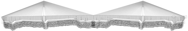
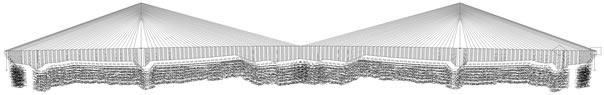
The spacing of the main cables has critical influence not only on the structural efficiency during construction and in the completed system but also on the appearance of the bridge. In this evaluation, the main cables are realistically arranged at spacing of 7.0 m, 10.5 m and 14.0 m (Figures 1 to 3). Structural analysis is performed for the whole system considering each spacing to compare the stresses developed in the girder with regard to the loads governing the design that are the permanent loads, the live loads and the replacement and breakage of cables and determine the appropriate spacing of the cables. Since this evaluation focuses on the effects of the external forces, the prestressing tendons inside the cross-section of the hybrid cable-stayed bridge are not included in
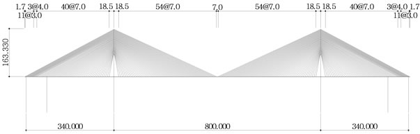
Figure 1. Cable spacing of 7.0 m.
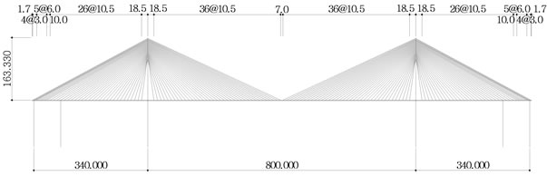
Figure 2. Cable spacing of 10.5 m.
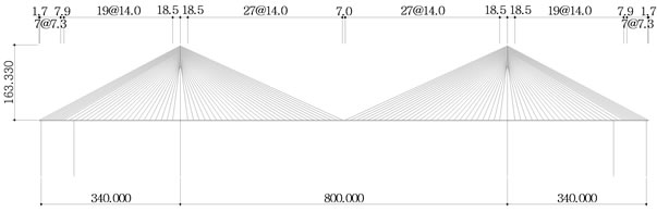
Figure 3. Cable spacing of 14.0 m.
the models as being corresponding to internal forces.
The amount of cables used in each spacing is presented in Figure 4, where the X axis represents the cable spacing. In Figure 4, the values of percentage were calculated relatively on the basis of the amount of the cable at cable spacing 10.5 m. It is known that the total weight of the cables in a cable-stayed bridge does not vary with shorter spacing. In this evaluation, the change is seen to be less than 2%. However, this observation holds only for the amount of cables but does not consider the increase of the number of anchors with the shortening of the cable spacing, which affects the economic efficiency of the bridge.
Tables 1 and 2 arrange the stresses developed in the upper girder under the application of the load combinations involving the permanent and live loads as principal loads, and the replacement and breakage of cable. The compressive stresses occur at the pylon whereas the tensile stresses occur at the center of the main span. Under the combination of the principal loads, the stress developed in the upper girder experiences insignificant change according to the variation of the cable spacing but appears to increase with longer cable spacing under the cable replacement and breakage combinations. The compressive stress at the whole remains below the allowable stress while the tensile stress in the top chord exceeds the allowable stress in all cases indicating the need for strengthening by prestress.
Figure 5 plots the amounts of tendons to be arranged
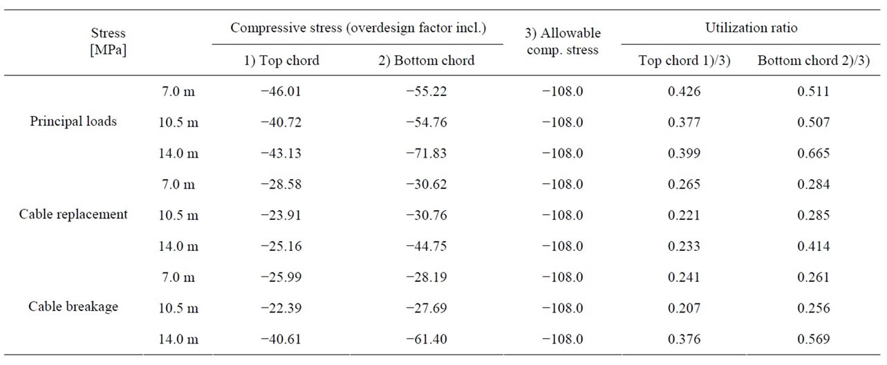
Table 1. Compressive stress by allowable stress combination (pylon).
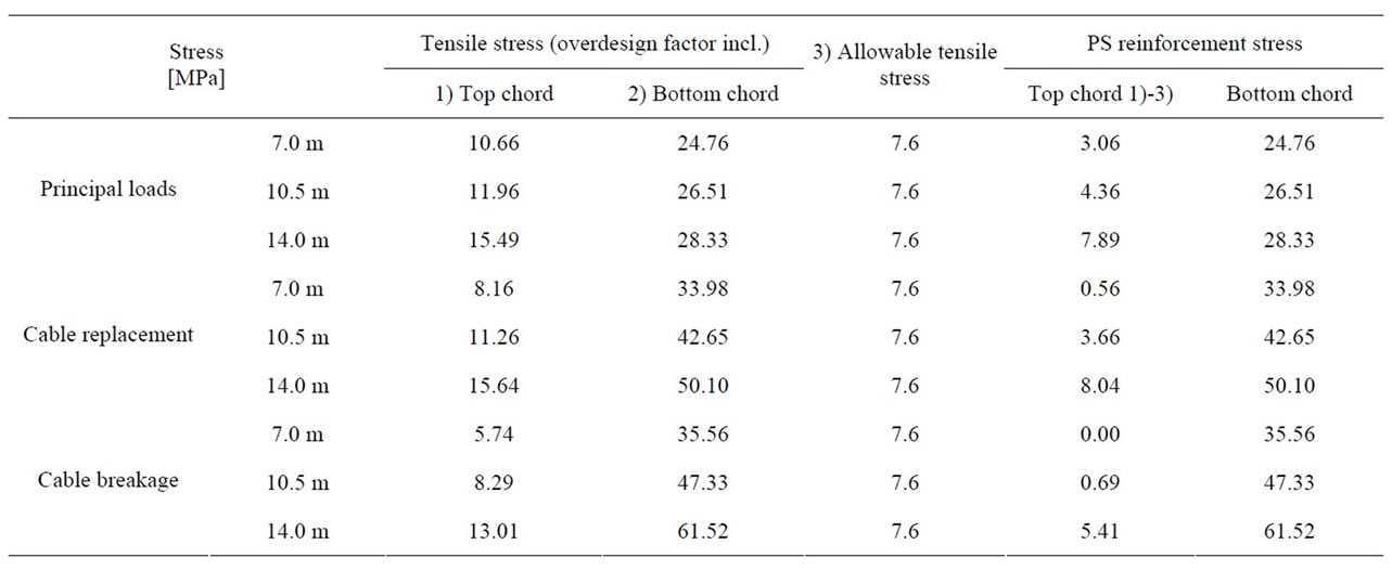
Table 2. Tensile stress by allowable stress combination (center of main span).
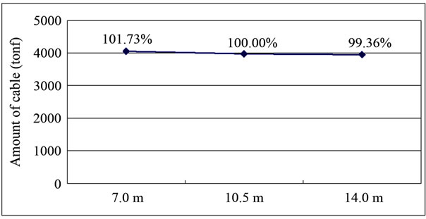
Figure 4. Amount of cables per cable spacing.
in the cross-section exceeding the allowable tensile stress per cable spacing of the hybrid cable-stayed bridge. These amounts are computed assuming that the tendons installed at mid-span will resist axially by being arranged at the centroid of the cross-section. For the cable spacing of 14.0 m, the prestress stress to be introduced in the up-
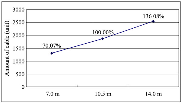
Figure 5. Amount of tendons required per cable spacing.
per girder reaches a high value of 53.52 MPa, which represents a surplus in steel wires of 36% compared to the 10.5 m cable spacing. Following, the additional arrangement of steel wires all along the stiffening girder to prepare for extreme events will cause not only the increase of the construction cost but also the extension of the construction period.
Figure 6 compares the construction cost according to the cable spacing for the amount of tendons shown in Figure 5 as the sum of construction costs of the upper girder, steel wires, cables (including the anchorages) and pylons. The results indicate that the cable spacing of 10.5 m is the most cost efficient but with a benefit below 1%.
2.2. Check of Side Span Length Ratio
Determining the length of the main span is the most important process in the design of the cable-stayed bridge. However, the structural behavior of the whole system varies according to the length of the side spans even if the length of the main span has been decided. This side span length ratio is also influencing significantly the economic efficiency. In this study, the side span length ratio is determined by examining the stresses developed in the girder and the negative reactions occurring in the piers by performing analysis of the whole system subjected to the permanent loads and live loads as the loads governing the design for the cases where the length of the main span is fixed to 800 m and the side span length ratio is 0.4 (320 m), 0.425 (340 m) and 0.5 (400 m).
Figure 7 plots the amount of cable per side span length ratio. It can be seen that the amount of cable increases with larger side span length ratio due to the resulting increase of the length of the whole system. In addition, the amount of cable increases also when the side span length ration decreases because of the increase of the prestress force of the anchor cables needed to control the displacement of the pylons.
The side span length ratio of the cable-stayed bridge has direct effect on the negative reactions occurring at the anchor piers. Even if the small negative stresses do not provoke particular problem in the case of large side span length ratio, counter weight or tie down should be considered in such case. From the examination results, the occurrence of negative reactions at side span length ratio smaller than 0.45 necessitates the consideration of countermeasures (Figure 8).
Tables 3 and 4 arrange the stresses developed in the upper girder under the application of the load combinations involving the principal loads that are the permanent and live loads. It can be observed that the stresses developed in the upper girder subjected to the principal load combination increase with larger side span length ratio and, consequently increase the use of tendons.
Figure 9 plots the amount of tendons necessary per side span length ratio and shows that the required amount of tendons increases with larger side span length ratio.
Table 5 lists the construction cost computed per side span length ratio for the amount of tendons of Figure 9.
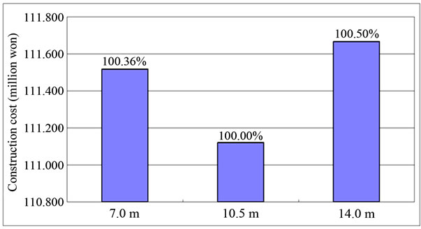
Figure 6. Construction cost per cable spacing.
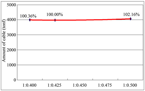
Figure 7. Amount of cable per side span length ratio (ton).
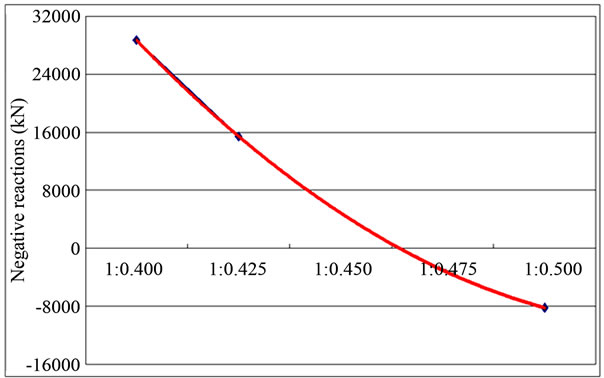
Figure 8. Negative reactions developed per side span length ratio (kN).
Here, the construction cost is the sum of the construction costs of the upper girder, steel wires, cables and pylons. It can be seen that the most economically efficient case corresponds to the side span length ratio of 0.425.
2.3. Check with Respect to Pylon’s Height
The span-to-rise ratio as the ratio of the ratio of the pylon’s height to the length of the main span is an important factor affecting not only the structural efficiency but also the aesthetical appearance of the bridge. In this check, the appropriate span-to-rise ratio is determined by examining the stresses developed in the girder and the
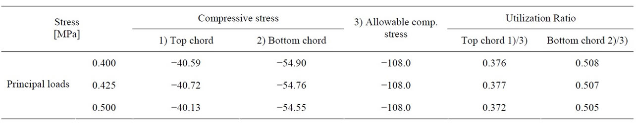
Table 3. Compressive stress by allowable stress combination (pylon).
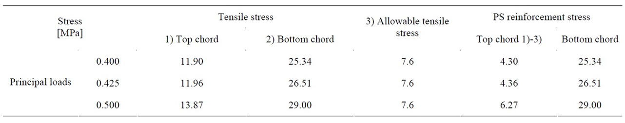
Table 4. Tensile stress by allowable stress combination (center of main span).
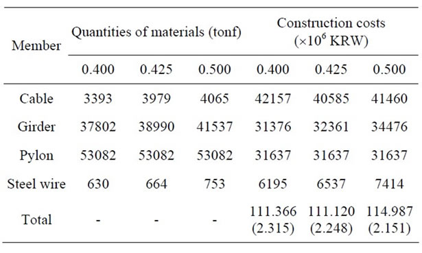
Table 5. Quantities of materials and construction costs per side span length ratio.

Figure 9. Amount of tendons per side span length ratio.
sectional forces occurring at the bottom of the pylons by performing analysis of the whole system subjected to the permanent loads and live loads as the loads governing the design for the cases where the length of the main span is fixed to 800 m and varying the height of the pylon.
Figure 10 plots the amount of cables required per span-to-rise ratio. The length of the cables increases with smaller span-to-rise ratio due to the resulting increase of
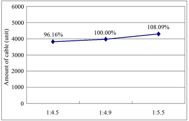
Figure 10. Amount of cables per span-to-rise ratio (ton).
the pylon’s height but the efficiency of the cables increases and reduces the amount of cables.
Even if the structural efficiency of the cables appears to be outstanding for higher pylons in the cable-stayed bridge, the quantities of materials required for the pylons increases resulting in longer construction period. Moreover, higher slenderness ratio of the pylon means also vulnerability to buckling and increase of the moment magnification factor at the bottom of the pylon, which finally results in the increase of the cross-section of the pylon. From Figure 11, the buckling safety factor falls down to 1.09 for the span-to-rise ratio of 1:4.5 and indicates that the overall cross-section of the pylon should be increased.
Tables 6 and 7 arrange the stresses developed in the upper girder under the application of the load combinations involving the principal loads that are the permanent and live loads. The stresses in the upper girder subjected to the principal load combination do not exhibit significant difference according to the span-to-rise ratio. Figure 12 plots the amount of tendons necessary per span-to-rise
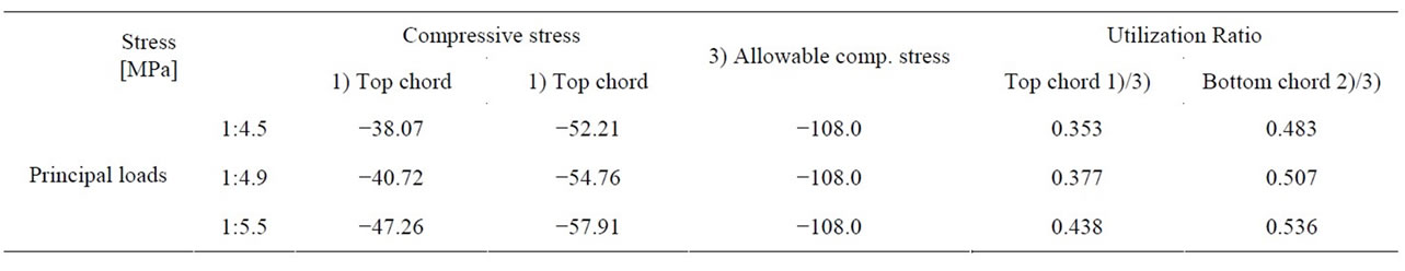
Table 6. Compressive stress by allowable stress combination (pylon).
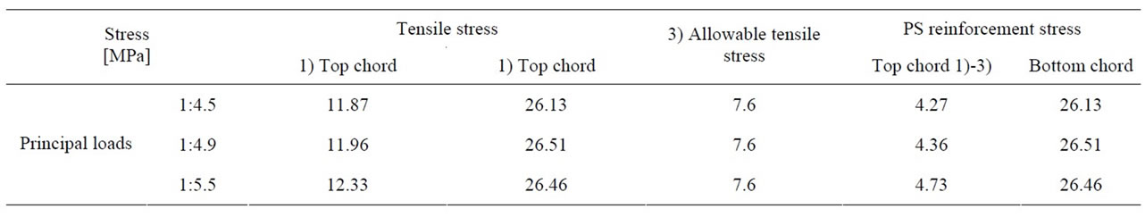
Table 7. Tensile stress by allowable stress combination (center of main span).
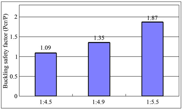
Figure 11. Check of buckling of pylon according to span-torise ratio.
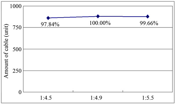
Figure 12. Amount of tendons per span-to-rise ratio.
ratio and shows that the span-to-rise ratio of 1:4.5 requires the smallest amount of tendons.
Table 8 lists the construction cost computed per spanto-rise ratio for the amount of tendons of Figure 12. Here, the construction cost is the sum of the construction costs of the upper girder, steel wires, cables and pylons. It can be seen that the most economically efficient case corresponds to the span-to-rise ratio of 1:4.9.
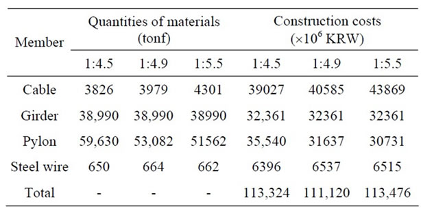
Table 8. Quantities of materials and construction costs per span-to-rise ratio.
2.4. Derivation of Optimal Structural System: Super Bridge 800
Based on these parametric analysis results, a cable spacing of 10.5 m is selected for Super Bridge 800, the hybrid cable-stayed bridge using UHPC girder (Figure 13). The superstructure is an edge girder with depth of 1.735 m and tapered cross beams with height varying from 1.735 m to 3.0 m (Figure 14). One cross-beam with sag of 3.5 m is disposed in each segment. The cables disposed at spacing of 10.5 m are planned to be tensioned after the installation of 3 segments. One segment weighs approximately 1100 kN.
3. Structural Check of Super Bridge 800
3.1. Check Per Construction Stage
The objective of the construction stage analysis is to verify the constructability of the structure and to verify if safety is secured during the erection. Considering the criteria related to the safety of the structure, the appropriateness of the management of the construction equipment and erection sequence as well as the eventual utilization of construction facilities like construction bent and
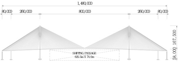
Figure 13. Super Bridge 800.
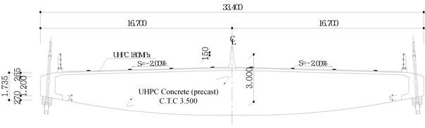
Figure 14. Standard cross-section.
the selection of the position at which they will be used are determined and verified by means of the construction stage analysis.
During the erection, the cable-stayed bridge system is featured by the nonlinearities of the cables, stiffening girder and pylons which turn to behave nearly linearly in the completed structure. Therefore, the ranges of the member forces to occur under the load combinations in the completed system are selected at first and considered during the construction stage analysis to verify the tension of the cables at completion. The final tensioning of the cables is obtained through repetitive calculations to put the member forces within the allowable ranges by varying the tension of the cables during the erection.
The analysis was performed by dividing the construction into 280 successive steps. The analysis of the completed system was conducted considering all the member forces at completion and 10,000 days after completion. It was assumed that, when a construction stage was involving several processes, these processes were implemented concurrently.
Figure 15 represents the sectional forces in the girder during the closure of the central span at step 126. Figure 16 shows the sectional forces in the girder during the application of the secondary permanent loads at step 126.
When the length of the cantilever is the longest, known as the most dangerous case during the erection just before the closure of the side spans, safety check during the erection is performed considering all the loads provoking unbalanced moments in the girder. Table 9 arranges the check results relative to the allowable stresses under the application of these unbalanced loads during the erection.
3.2. Check for Cable Replacement and Breakage
The cable replacement is normally checked under the condition that one design lane at proximity of the rele-
 (a)
(a)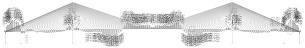 (b)
(b)
Figure 15. Section forces at step 126 (at closure of central span). (a) Axial forces; (b) Moments.
 (a)
(a) (b)
(b)
Figure 16. Section forces at step 126 (at application of secondary permanent loads). (a) Axial forces; (b) Moments.
vant cable is controlled but all the lanes are loaded considering the vehicle for replacement. The tension of the cables is obtained first with respect to the load combinations. Thereafter, this tension is applied inversely to the structural system to simulate the removed cable [4,5]. The final tension is finally computed by adding the tension of the cable corresponding to the load combination and the additional tension caused by the replacement. Table 10 lists the stresses developed during the replacement of cable.
For the cable breakage analysis, the relevant cables are selected at proximity of the sections of the stiffening girder and at several points considered to be vulnerable. The vulnerable sections are positioned at 4 locations that are the cables closest to the pylons, the cables at midspan and 3/4 span and the central span. Since the time needed for cable breakage is in direct correlation with the impact, the check assumes that sudden cable breakage during a period of 0.01 sec to provide conservative results. The damping of the structure is assumed to be 0.02 [6]. Table 11 lists the dynamic analysis results according to the positions of the vulnerable sections.
3.3. Wind Stability Check
The structural safety of the structure is verified during the erection and at completion considering the dynamic wind load effect by means of buffeting analysis for Super Bridge 800. Structural safety is checked by proposing the installation of wind stabilizing cables during the construction stage known to be the most vulnerable to dynamic wind loading.

Table 9. Check of allowable stresses during the application of unbalanced loads.
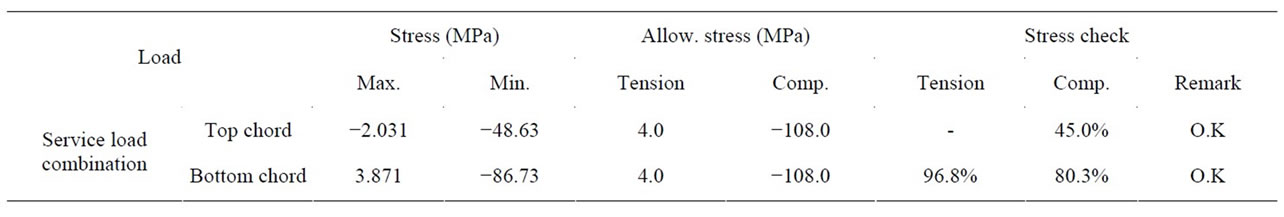
Table 10. Check of allowable stress during cable replacement.
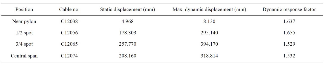
Table 11. Dynamic analysis results at cable breakage.
The static three-force components and flutter coefficients determined through 2-dimensional wind tunnel test are applied to evaluate the dynamic wind load effect. It is verified that the stiffening girder and pylons of the completed system secure structural stability and serviceability to dynamic wind load. The results of the dynamic wind load check for the main span before closure reveal that the stiffening girder and pylons secure the structural stability for the vertical vibrations as a system where the side spans are closed, and do not need particular vibration control measures. For the structural system before closure of the side spans, it appears that vibration control should be applied for the stiffening girder since the girder in cantilever state during the construction is vulnerable to vertical vibrations caused by the dynamic wind loading. Therefore, wind stabilizing cables are proposed.
Here, the wind cables shall be initially prestressed during the installation to prevent any loss of the tension. The proposed installation of the wind cables plans to cross the cables at 60.5 m with reference to the pylon and dispose the vertical wind cables on the side spans and main span at 12.5 m and 186.5 m with reference to the pylon. The check for this proposal verified that the stiffening girder and pylons secured the structural stability through this solution.
4. Conclusion
This study developed an optimal structural system for the hybrid cable-stayed bridge having its main structural members made of UHPC with compressive strength of 200 MPa and durable lifetime of 200 years. The optimal structural system was derived by conducting analyses related to the cable spacing, side span length ratio and pylon’s height, and the derived structural system was verified to secure stability through structural checks. In addition, calculations showed that Super Bridge 800 developed in this study involved amounts of 57,949 tonf and 985 tonf of UHPC and steel wires, respectively. The computation of the costs based on these material quantities and unit prices of 2010 revealed that the construction cost reduced by about 23.3% compared to Incheon Bridge, a cable-stayed bridge of identical size completed in 2009 in Korea and that Super Bridge 800 secures significant cost competitiveness.
5. Acknowledgements
This work was supported by the “Development of accelerated construction technologies for high pylons” project of the Super Long Span Bridge R&D Program. The authors express their gratitude for the support.
REFERENCES
- Korea Institute of Construction Technology, “Development of Design and Construction System Technology for Hybrid Cable Stayed Bridge,” KICT 2009-102, 2009.
- Korea Institute of Construction Technology, “Development of Design and Construction System Technology for Hybrid Cable Stayed Bridge,” KICT 2010-088, 2010.
- Korea Institute of Construction Technology, “Development of Design and Construction System Technology for Hybrid Cable Stayed Bridge,” KICT 2011-076, 2011.
- Ministry of Construction and Transportation, “Highway Bridge Design Code,” 2005.
- Korean Society of Civil Engineers, “Design Guidelines for Cable-supported Steel Bridges,” 2007.
- C. H. Lee, W. J. Chin, E. S. Choi and Y. J. Kim, “An Experimental Study on the Joints in Ultra High Performance Precast Concrete Segmental Bridges,” Journal of the Korea Concrete Institute, Vol. 23, No. 2, 2011, pp. 235-244. doi:10.4334/JKCI.2011.23.2.235
NOTES
*Corresponding author.