Engineering
Vol.5 No.10A(2013), Article ID:37393,7 pages DOI:10.4236/eng.2013.510A005
A New Approach for Converting Renewable Energy to Stable Energy
1Electrical Power and Machines, Faculty of Engineering, Zagazig University, Zagazig, Egypt
2Electrical and Computer Engineering, Higher Technological Institute, 10th of Ramadan City, Egypt
Email: m_mtalaat@zu.edu.eg, Reda.Edris@gmail.com
Copyright © 2013 Mohamed Talaat et al. This is an open access article distributed under the Creative Commons Attribution License, which permits unrestricted use, distribution, and reproduction in any medium, provided the original work is properly cited.
Received June 9, 2013; revised July 9, 2013; accepted July 16, 2013
Keywords: Renewable Energy; Stable Energy; Energy Stored; Wind Farm; Solar Energy; Application of Renewable Energy
ABSTRACT
A renewable energy plant which relies on wind speed or solar insolation is unreliable because of the stochastic nature of weather patterns. It is theorized that by using multiple renewable energy plants in separate areas of a region, the different weather conditions might approach a probabilistically independent relationship. The goal of this paper is to utilize the power system technology to help disseminate wind and solar power systems to get a stable energy. A new approach to get appropriate stable energy is achieved by using the interrupted energy that obtained from wind farm and solar insolation. This is achieved by lifting water to a higher level with appropriate pumps and storing it in the form of potential energy. Then a stable energy is obtained by reliving water to the lower level. In this paper, the efficiency obtained from the renewable energy is compared with that obtained from traditional ones. An experimental model to simulate the process of converting the renewable energy to a stable energy is presented. The obtained results from experimental model explained that the renewable energy can be converted to a stable one with high efficiency.
1. Introduction
Renewable energy sources, such as wind and solar, have vast potential to reduce dependence on fossil fuels and greenhouse gas emissions in the electric sector. Climate change concerns, state initiatives including renewable portfolio standards, and consumer efforts are resulting in increased deployments of both technologies. Both solar PV and wind energy have variable and uncertain sometimes referred to as “intermittent” output, which are unlike the dispatchable sources used for the majority of electricity generation [1-2].
The variability of these sources has led to concerns regarding the reliability of an electric grid that derives a large fraction of its energy from these sources as well as the cost of reliably integrating large amounts of variable generation into the electric grid [3-5]. Because the wind doesn’t always blow and the sun doesn’t always shine at any given location, there has been an increased call for the deployment of energy storage as an essential component of future energy systems that use large amounts of variable renewable resources. However, this often-characterized “need” for energy storage to enable renewable integration is actually an economic question [2,4].
To determine the potential role of storage in the grid of the future, it is important to examine the technical and economic impacts of variable renewable energy sources. It is also important to examine the economics of a variety of potentially competing technologies including demand response, transmission, flexible generation, and improved operational practices. While there are clear benefits of using energy storage to enable greater penetration of wind and solar, it is important to consider the potential role of energy storage in relation to the needs of the electric power system as a whole [2,5].
In this paper, the role of energy storage in the electricity grid has been explored, focusing on the effects of variable renewable sources (primarily wind and solar energy), a new technique of simulation like FEM and CSM are used to simulate the field and energy [6-7]. The goal is to utilize and forecast the power system technology [8] to help disseminate wind and solar power systems to get a stable energy. This is achieved by lifting water and storing electrical energy in the image of potential energy to lift water to a higher level with appropriate pumps then obtain a stable energy by releasing electricity impulsively water to the lower level. The current role that energy storage plays in meeting the varying electricity demand is important. The impact of variable renewable on the grid is then discussed, including how these energy sources will require a variety of enabling techniques and technologies to reach their full potential. Finally, the potential role of several forms of enabling technologies including energy storage has been evaluated.
2. Energy Storage Technologies
A variety of technologies are available for storage of energy in the power system [9,10]. When identifying the most relevant storage solutions it is necessary to include considerations on many relevant parameters, such as: cost, lifetime, reliability, size, storage capacity and environmental impact. All these parameters should be evaluated against the potential benefits of adding storage in order to reach a decision on which type of storage should be added. There may also be cases where the value of adding storage is not large enough to justify such an investment.
Energy storage technologies for power applications can be divided according to the form of energy stored: Mechanical, electro-chemical, electromagnetic, or thermal storage.
Mechanical storage includes pumped hydro storage, CAES and flywheels. Electrochemical storage includes all types of batteries and fuel cells, and electromagnetic storage includes super capacitors and superconducting magnetic energy storage. Each technology has certain attributes with regard to for example storage capacity, power, reaction time and cost [10].
Figure 1 shows some of the most relevant storage technologies, grouped according to the form of stored energy as well as energy storage capacity. The medium capacity storage technologies seem very relevant for storage in relation to wind power. The medium capacity storage technologies are primarily batteries and flow batteries, which all have the advantage in relation to wind power plants that they are modular and scalable.
2.1. High-Energy Batteries
For many batteries, there is considerable overlap between energy management and the shorter-term applications discussed previously. Furthermore, batteries can generally provide rapid response, which means that batteries “designed” for energy management can potentially provide services over all the applications and timescales discussed.
Several battery technologies have been demonstrated or deployed for energy management applications. In addition to the chemistries discussed previously, the commercially available batteries targeted to energy management include two general types: high-temperature batteries and liquid electrolyte flow batteries.
2.2. Pumped Hydro Storage (PHS)
Pumped hydro is the only energy storage technology deployed on a gigawatt scale in the United States and worldwide. Many of the sites store 10 hours or more, make the technology useful for load leveling. PHS is also used for ancillary services. PHS uses conventional pumps and turbines and requires a significant amount of land and water for the upper and lower reservoirs. PHS plants can achieve round-trip efficiencies that exceed 75% and may have capacities that exceed 20 hours of discharge capacity. Environmental regulations may limit large-scale above-ground PHS development. However, given the high round-trip efficiencies, proven technology, and low cost compared to most alternatives, conventional PHS is still being pursued in a number of locations.
2.3. Compressed Air Energy Storage (CAES)
CAES technology is based on conventional gas turbine
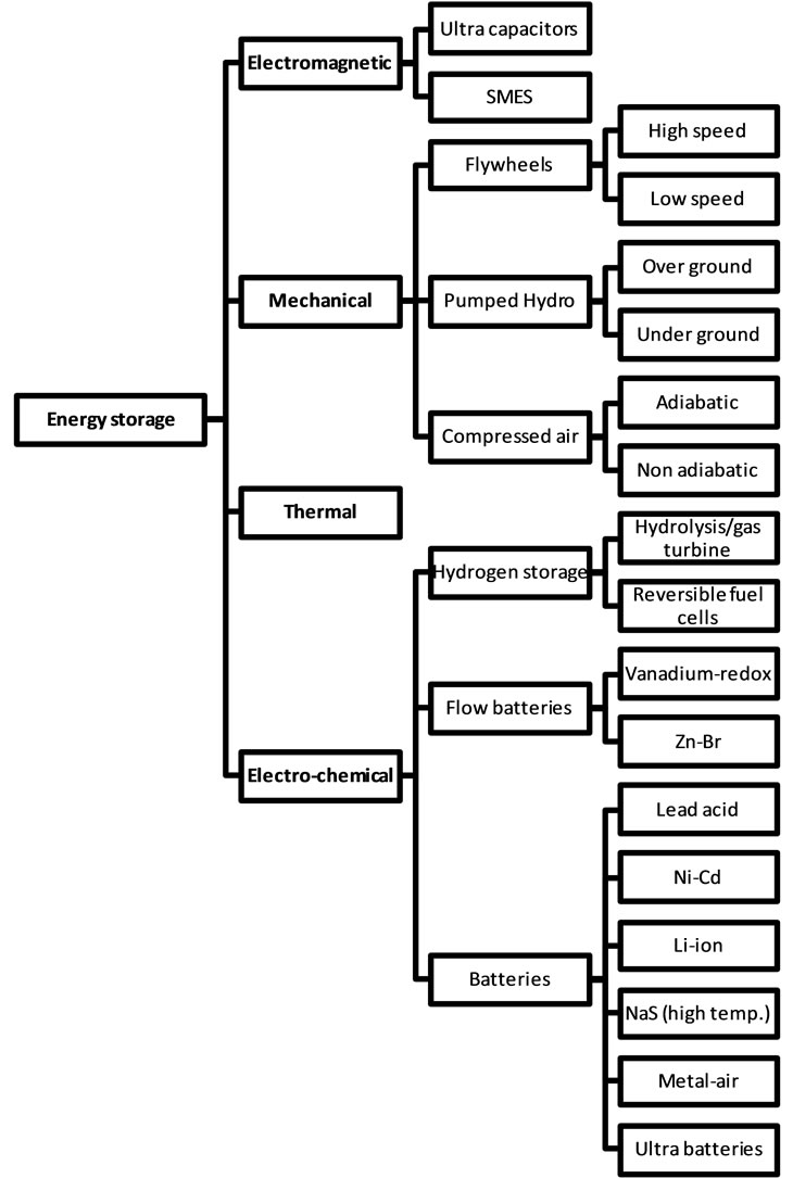
Figure 1. Energy storage technologies grouped according to form of energy as well as energy storage capacity. Typical timescales have been indicated [10].
technology and uses the elastic potential energy of compressed air. Energy is stored by compressing air in an airtight underground storage cavern. To extract the stored energy, compressed air is drawn from the storage vessel, heated, and then expanded through a high-pressure turbine that captures some of the energy in the compressed air. The air is then mixed with fuel and combusted, with the exhaust expanded through a low-pressure gas turbine. The turbines are connected to an electrical generator.
The primary disadvantages of CAES are the need for an underground cavern and its reliance on fossil fuels. Alternative configurations for CAES have been proposed using manufactured above-ground vessels, new turbine designs to reduce fossil fuel use, or designs that re-use the heat of compression and avoid fuel use altogether.
2.4. Thermal Energy Storage
Thermal energy storage is sometimes ignored as an electricity storage technology because it typically is not used to store and then discharge electricity directly. However, in some applications, thermal storage can be functionally equivalent to electricity storage. One example is storing thermal energy from the sun that is later converted into electricity in a conventional thermal generator. Another example is converting electricity into a form of thermal energy that later substitutes for electricity use such as electric cooling or heating.
In the low capacity end, ultra capacitors may be of relevance in relation to wind power conditioning. Hydrogen fuel cells may also be relevant, both as mediumand high capacity storage.
Due to short-term energy market closure delay, dispatch levels of wind farm-energy storage system should be decided according to wind power LF [8]. The forecast accuracy and dispatch strategy are both of importance to energy storage sizing. Next, wind power forecast method and the dispatch strategy for minimizing size of energy storage system will be studied.
The low capacity storage technologies seem less relevant in relation to overall improvement of wind energy quality because of high cost pr. unit stored energy and relatively short storage time scale. The very high capacity technologies, PH storage and CAES, involve large investments and civil engineering efforts, as well as special requirements with regard to placement. But these technologies may well be the best solution in relation to large scale storage, where a few major energy storage facilities ensure overall power system stability. Especially in cases where hydro-electric plants with unused storage capacity already exist, large benefits may be obtained by combining them with wind power plants.
3. Mathematical Model
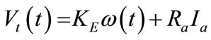
The PM DC motor is the one that is most commonly used in PVPS. It does not need field current and the magnetic field is provided separately by the permanent magnet. When a voltage Vt is applied at time t across the armature winding including an inductance La and resistance Ra. Then the relationship between Vb La and Ra can be expressed as.
 (1)
(1)
where; Ia is the motor current and Eb is the internally induced voltage by the motor. Which is proportional to motor rotational speed  (red/sec) such that,
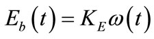 (2)
(2)
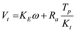
where; KE is the voltage constant in V.sec/red. Combining Equations (1) and (2) gives
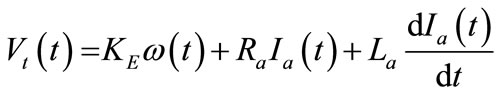 (3)
(3)
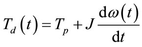
The motor develops an electric torque Td which basically depends on the motor current
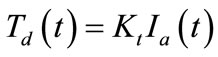 (4)
(4)
where; Kt is the torque constant (N·m/A).
The lead torque is the pump torque Tp which depends on the pump type, as will be seen later .If the motor pump coupling losses are neglected, the dynamic equation of the motor and load is,
 (5)
(5)
where; J is the moment of inertia of motor-pump system (N·m·sec2/red). Combining Equations (4) and (5) gives,
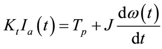 (6)
(6)
The two first order differential Equations (3) and (6) represent the dynamic model of the system. The dynamic performance can be obtained by solving these equations numerically to obtain the instantaneous values of the motor current and speed.
Under steady sate conditions Equations (3) and (6) become.
 (7)
(7)
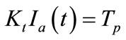 (8)
(8)
Equations (7) and (8) represent the mathematical model of the system under steady conditions. The solution of these equations at any climatic conditions gives the operating parameters of the motor current and speed.
 (9)
(9)
The torque constant
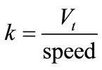 (10)
(10)
Hence the torque is 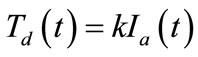 and the output power is given as
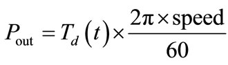 (11)
(11)
4. Experimental Model
An experimental model was established to simulate the mechanism of utilize the energy from wind farm and solar energy and convert this energy to a stable energy using a water pump see Figure 2.
A model of wind turbine or photovoltaic cell was connected to a DC pump through a PLC device. The DC pump was 24 V and 400 mA. The pump received the interrupted energy from wind if it was active or PV cell if it was active, the activation decided through the PLC sensor device. The water pump using these interrupted energy to left the water to a high tank, which use this water as a hydraulic high dam to convert this energy to a stable energy.
The performance of the wind turbine observation depends on the amount of emf produced with variable speed of wind. Also the characteristics of the DC pump depend on the amount of current taken from pump at each speed to lift the water to high tank.
A new microcontroller circuit is designed for measuring the values of current, voltage, and speeds, see Figure 3.
5. Results
The torque constant according to Equation (10) is given as
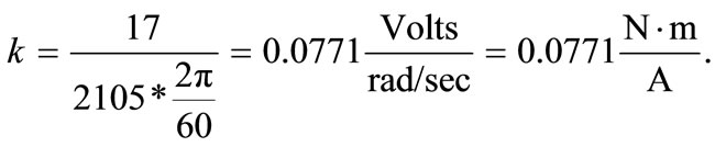
where, Vt = emf – armature drop = 24 – 7 = 17 Volts, and the corresponding angular speed is given as 2105 rpm, as given from Table 1 at no load of pump.
The voltage output from wind turbine, and the current delivered to the pump at different speed of wind are given in Table 2. Also the torque calculated from Equation (4), and the calculated powers from Equation (11) are calculated in the same table.
Figure 4 shows the variation of output voltage from wind turbine with wind speed at no load. Also Figure 5 shows the variation of delivered current to the DC pump with each wind turbine speed.
The variation of output torque with output current of wind turbine is shown in Figure 6. Also Figure 7 shows the variation of DC pump current with wind turbine speed. Figure 8" target="_self"> Figure 8 gives the variation of wind efficiency with wind speed.
Finally, the overall efficiency of the wind and pump is calculated and shown in Figure 9, which gives a stable power.
6. Discussion
Tables 1 and 2, also Figures 4-7 show that the energy obtained from the wind turbine with no load or to the DC pump is not stable and interrupted, so a curve fitting is
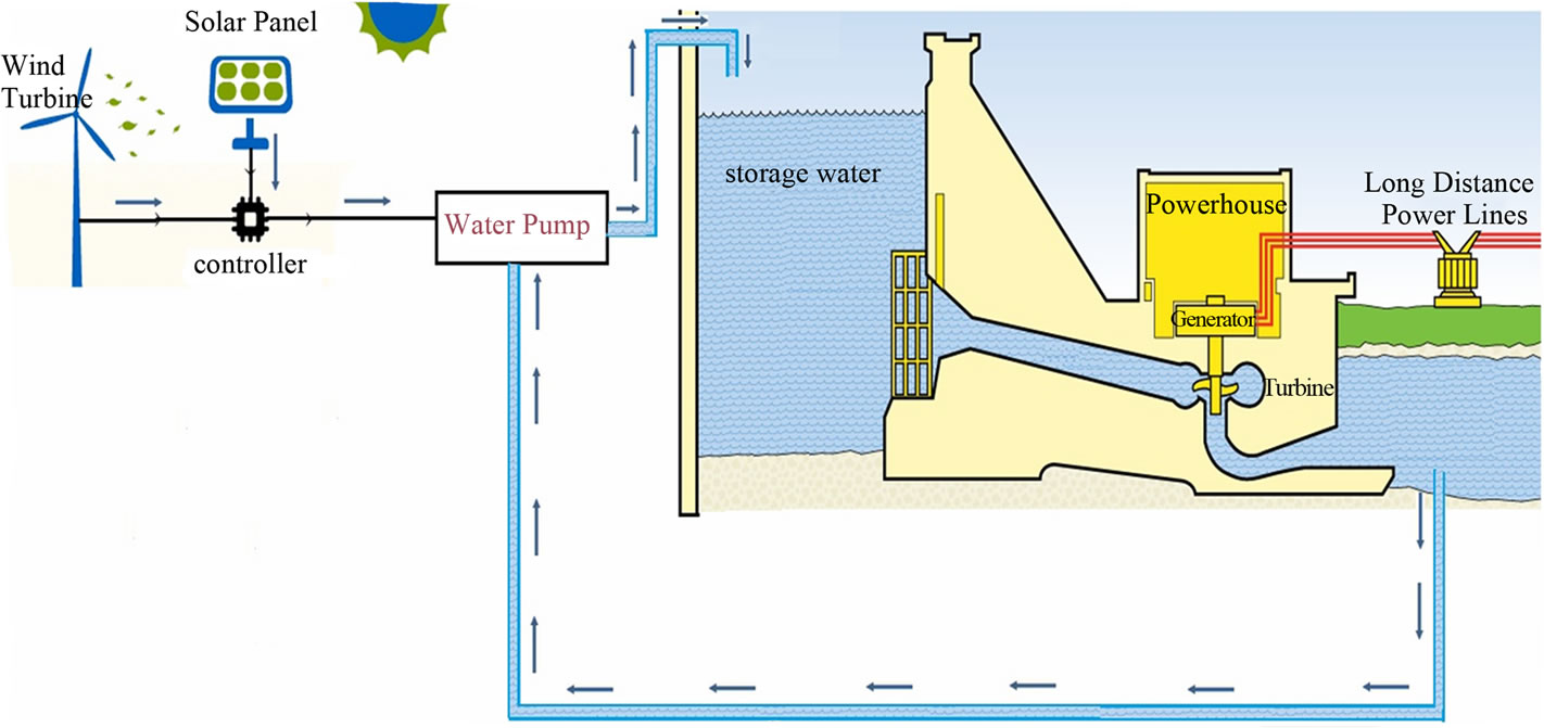
Figure 2. Energy storage simulation from wind and solar.
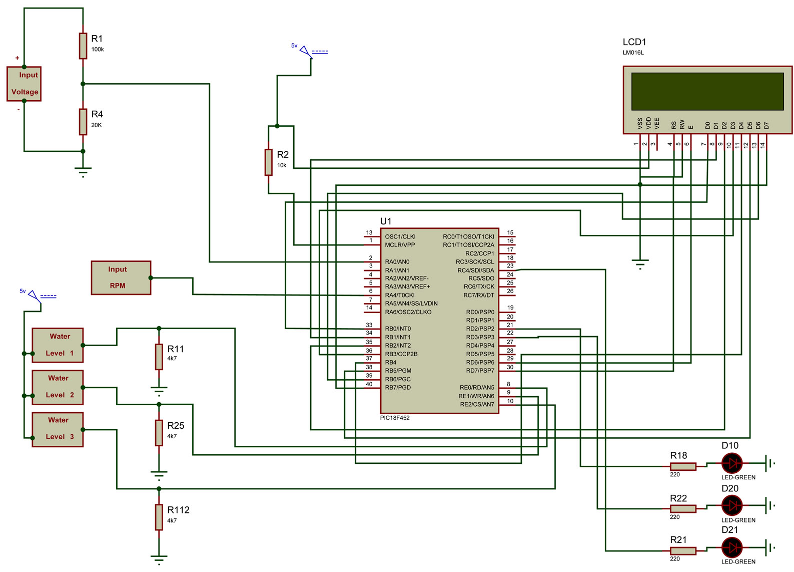
Figure 3. Microcontroller circuit used for measuring voltage, current, and speed.
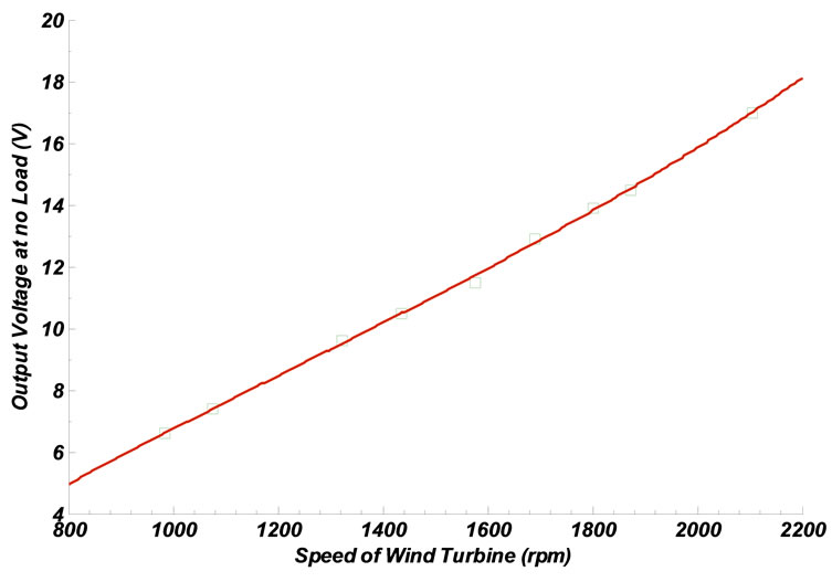
Figure 4. Variation of output no load voltage with wind turbine speed.
used to get a stable curve. Also Figure 8 explained that the variation of efficiency of wind with wind speed is not stable. So instead to use this unstable energy for power generation which will be unstable also, the new technique uses this unstable energy for lifting the water to high tank to generate a stable energy, according to Figure 9 the overall efficiency gives a stable energy.
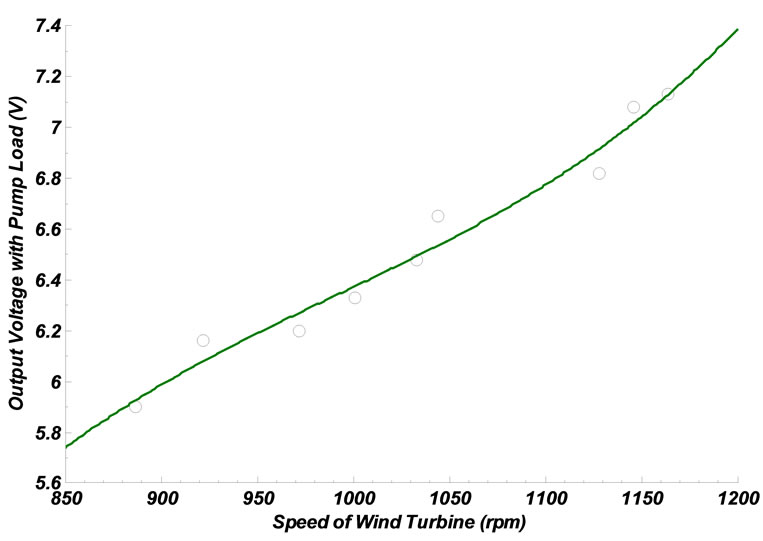
Figure 5. Variation of output voltage with wind turbine speed.
7. Conclusion
An experimental model to simulate the process of converting the renewable energy to stable energy is presented. A new approach to get appropriate stable energy is achieved by using the interrupted energy that obtained from wind farm and solar insolation. This is achieved by
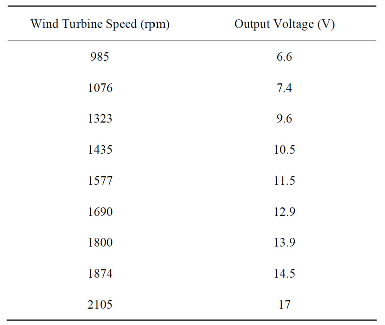
Table 1. Variation of output voltage with wind turbine speed at no load.
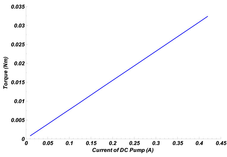
Figure 6. Variation of output torque with output current.
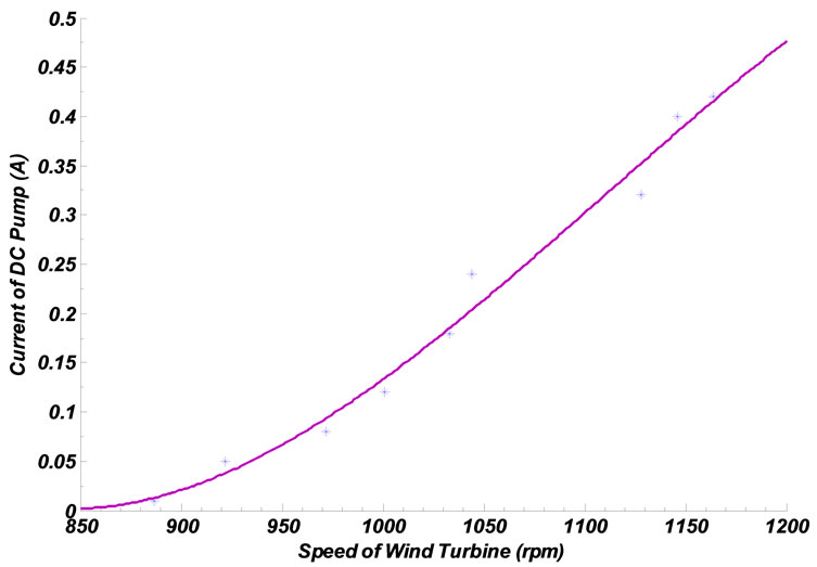
Figure 7. Variation of DC pump current with wind turbine speed.
lifting water and store electrical energy in the image of potential energy to lift water to a higher level with appropriate pumps then obtain a stable energy by releasing
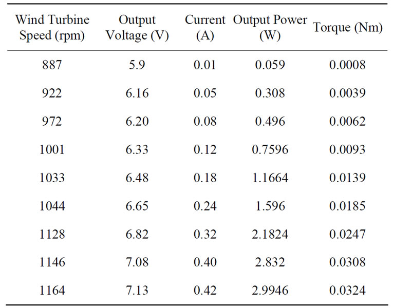
Table 2. Variation of delivered current to DC pump with wind turbine speed.
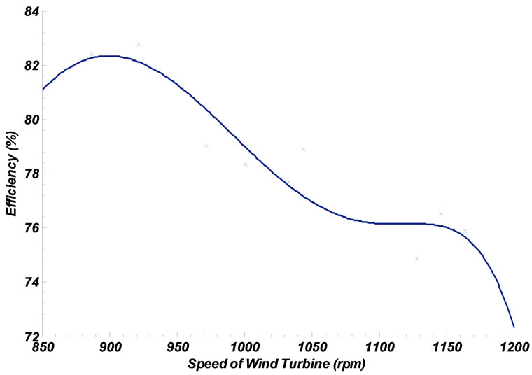
Figure 8. Variation of wind efficiency with wind turbine speed.
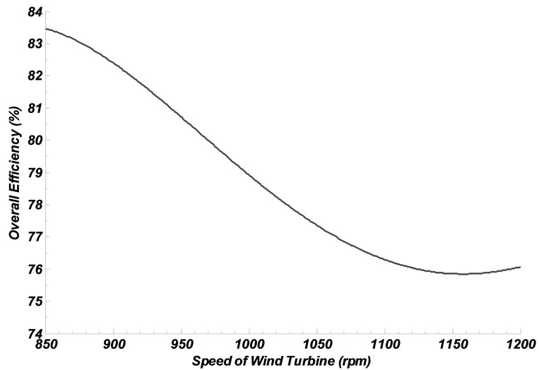
Figure 9. Variation of overall efficiency with wind turbine speed.
electricity impulsively water to the lower level. The obtained results from experimental model explained that the renewable energy can be converted to a stable one with high efficiency.
REFERENCES
- World Wind Energy Association, “Highlights of the World Wind Energy Report,” 2009. http://www.wwindea.org/home/index.php
- “The Role of Energy Storage with Renewable Electricity Generation,” Technical Report NREL/TP-6A2-47187, 2010. http://www.osti.gov/bridge
- L. L. Freris, “Wind Energy Conversion Systems,” Prentice Hall, Upper Saddle River, 1990.
- B. C. Ummels, E. Pelgrum and W. L. Kling: “Integration of Large-Scale Wind Power and Use of Energy Storage in the Netherlands’ Electricity Supply,” IET Renewable Power Generation, Vol. 2. No. 1, 2008, pp. 34-46.
- E. Spahic, G. Balzer, B. Hellmich and W. Münch, “Wind Energy Storages—Possibilities,” IEEE PowerTech, 2007.
- M. Talaat and A. El-Zein, “A Numerical Model of Streamlines in Coplanar Electrodes Induced by Non-Uniform Electric Field,” Journal of Electrostatics, Vol. 71, No. 3, 2013, pp. 312-318. http://dx.doi.org/10.1016/j.elstat.2012.12.034
- M. Talaat, “Charge Simulation Modeling for Calculation of Electrically Induced Human Body Currents,” IEEE Annual Report Conference on Electrical Insulation and Dielectric Phenomena CEIDP, West Lafayette, 17-20 October 2010, pp. 644-647.
- M. A. Farahat and M. Talaat, “The Using of Curve Fitting Prediction Optimized by Genetic Algorithms for Short- Term Load Forecasting,” International Review of Electrical Engineering (IREE), Vol. 7, No. 6, 2012, pp. 6209- 6215.
- M. Swierczynsky, R. Teodorescu, C. N. Rasmussen, P. Rodriguez and H. Vikelgaard, “Storage Possibilities for Enabling Higher Wind Energy Penetration,” EPE Wind Energy Chapter Symposium, Stafford, 15-16 April 2010.
- C. N. Rasmussen, “Energy Storage for Improvement of Wind Power Characteristics,” IEEE PowerTech, Trondheim, 2011.
Nomenclature A
PV: Photovoltaic FEM: Finite Element Methods CSM: Charge Simulation Method LF: Load Forecasting CAES: Compressed Air Energy Storage PH: Pumped Hydro PM: Permanent Magnet PHS: Pumped Hydro Storage PVPS: Photovoltaic Pump Storage