Engineering
Vol. 5 No. 8 (2013) , Article ID: 35531 , 11 pages DOI:10.4236/eng.2013.58079
Effect of Zinc Galvanization on the Microstructure and Fracture Behavior of Low and Medium Carbon Structural Steels
1Nucor Steel Corporation, Marion, USA
2Nucor Steel Corporation, Decatur, USA
3Mechanical Engineering Department, Tuskegee University, Tuskegee, USA
Email: ignatius.okafor@nucor.com, ron.omalley@nucor.com, aglanh@mytu.tuskegee.edu
Copyright © 2013 Ignatius C. Okafor et al. This is an open access article distributed under the Creative Commons Attribution License, which permits unrestricted use, distribution, and reproduction in any medium, provided the original work is properly cited.
Received May 1, 2013; revised June 1, 2013; accepted June 8, 2013
Keywords: Galvanized Steel; Liquid Metal Embrittlement; Microstructure; Elemental Mapping; Fracture Resistance; etc.
ABSTRACT
Microstructure and fracture behavior of ASTM 572 Grade 65 steels used for wind tower applications have been studied. Steels of two carbon level chemistries designed for this grade were used in the study. Fracture toughness of the steels was studied using 3-point bend test on samples coated with zinc and not coated with zinc. Lower carbon steel showed higher resistance to fracture than medium carbon steel after zinc galvanization. SEM study suggests that zinc and zinc bath additives that migrated to crack tips are responsible for the loss in ductility. The phenomenon of Liquid Metal Embrittlement (LME) is suggested to have taken place. Zinc bath additives traced at crack zones are suggested to have migrated at the zinc galvanizing temperatures.
1. Introduction
Hot-dip galvanizing is one of the most efficient and economic ways of protecting steel from corrosion. This has been the most common practice for almost a century as it is safe and meets resource preservation for the steel industry. Hot-dipping uses a “dip and drain” method accompanied by standard practices which include design adjustments and size restrictions to galvanize the steels [1-3]. These standards provide better galvanizing techniques throughout the world to protect almost all structural steels. However, during the past decade or so, many reports [4-7] have revealed cracking in hot galvanized construction or structural steels. This cracking has occurred after galvanizing prior cold formed, welded and or prior flame cut steels. The phenomenon behind this was variously reported as liquid metal embrittlement (LME), liquid metal assisted cracking (LMAC) or liquid metal induced cracking (LMIC) [4-7].
In this phenomenon the ductility of a solid metal becomes drastically reduced after surface contact with liquid metals that often have lower melting point/solidification temperatures than the solid metal. A glimpse at the numerous conclusions of a few researchers [8-12] leads to the following summary:
• embrittlement due to zinc have been reported to occur most frequently after dip galvanizing oxy-fuel cut, welded or sharply cold formed parts;
• zinc, like lead, bismuth, antimony and tin, are known to cause grain boundary separation in a form described as intergranular;
• in each situation the fractures are the result of, or at the location of some thermal or cold forming process, and almost always start from a stress riser such as sharp corners or pre-existing micro-cracks;
• upon examining the fracture surface it contains zinc or zinc reaction products; and
• while it is understood that materials that form intermetallic compounds normally do not experience liquid metal embrittlement, some researchers believe that the impurities (like tin and lead) in the coating material may be responsible for the contamination.
In his monumental work on this phenomenon, Kinstler [13] reported fewer but similar findings that are associated with LMAC. He concluded that:
a) the fractures are often intergranular;
b) the fractures occur at or result from some thermal or cold working process; and c) the fracture surface was coated with zinc or zinc reaction products.
However, earlier in the century a major study [11] had reported that most construction steels retained their mechanical and dynamic properties after hot dip galvanizing. These two opposing views naturally led to numerous studies in galvanizing related cracking in structural steels. Kinstler [14] gives an excellent review and documents most of these studies.
More importantly, the effect of zinc bath chemistry and steel chemistry on the processing of the zinc galvanization has a profound role. Elements such as silicon, manganese and phosphorus present in steel can accelerate the Zn-Fe reaction but, can result in a non uniform coating to brittle and non adherent coating. Also, nitrogen, which is easily diffusible, can accelerate aging under the thermal transient and can degrade the mechanical properties of the galvanized steels. Lead, commonly found in the zinc ores, has a concentration of about 1% in the galvanizing bath and enhances drainage of the molten zinc [15], thus improving uniformity of the coatings. Bismuth has similar characteristics as lead. Aluminum on the other hand adds brightness to the outer layer; nickel, tin, vanadium and titanium are beneficial to retarding the enhanced reactivity of zinc to steel; tin, acts to enhance drainage. The addition of tin and bismuth in the bath can be understood by the fact that these elements are rejected by the growth of the intermetallics and form a film around them and wet the steel. However, when a crack is present, these elements quickly reach the crack along with zinc and create a tin and bismuth rich, zinc poor composition [16].
The International Lead Zinc Research Organization sponsored experimental programs that are noteworthy [15]. The unpublished works of Kinstler on Cope cracking in galvanized structural beams and some others [17- 19] led the way towards creating more understanding of this phenomenon. In 2004, The American Institute of Steel Construction (AISC) spear headed a project to collect as much information as possible on this phenomenon [20].
Our interest in this work derived from two cases;in one a customer reported severe cracking in A572 Grade 65 material used for wind tower applications; and in the other, an ultra high strength steel (HSS) hollow tubing (Figure 1) used for structural applications cracked, after the material had been zinc galvanized. Material from the same heat of both materials had been sold to a second customer, but no such problems were detected after identical treatment. In consequence a second steel chemistry was designed to counter this phenomenon. This paper reviews only one material (A572 Grade 65 steel) for the current study. This new chemistry and the original chemistry were used to study this phenomenon. The research for the other material (HSS steel tubing) is currently undergoing study and results will be presented in a following paper.
2. Materials and Experimental
Two chemistries of grade X65 steel (one low carbon and the other medium carbon) used in this work were supplied by Nucor Steel Tuscaloosa. Table 1" target="_self"> Table 1 shows the steel chemistries.
The materials were supplied in the form of flat plates from which blanks were cut with their axis oriented along the rolling direction for the fabrication of fracture 3-point bend test specimens. The carbon content of the samples was specifically chosen to study the significance, if any, of carbon difference and effect of carbon equivalence (CeV).
Two sets of samples were cut from each grade. For ease of identification the low carbon grade plates were designated A and B while the medium carbon plates were designated as C and D. For each plate set (A and B; and C and D) respectively samples were further designated as parent (P) or galvanized (G) to further distinguish each sample’s experience or treatment. A set of 12 sample pieces were cut from each plate set A, B, C and D. Six pieces of each 12 set were parent (P) and the rest galvanized (G).
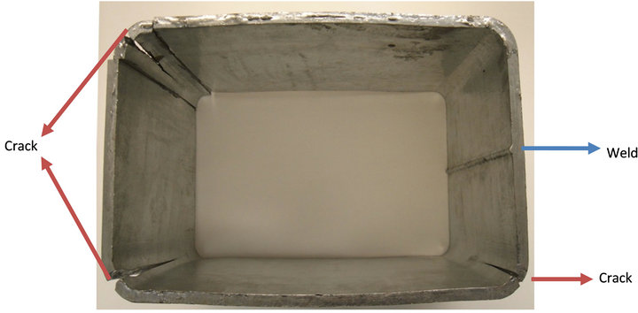
Figure 1. Cracks seen in the galvanized ultra high strength hollow structural steel (HSS) tubing.
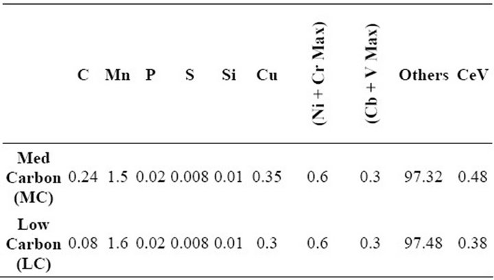
Table 1. Steel chemistries.
2.1. 3-Point Bend Tests
All specimens for 3-point bend tests were taken as described above and cut in the geometry and specimen dimensions shown in Figure 2. These specimens have the nominal dimensions of 75 mm in length with a two-point bottom load span of 63.5 mm. The top load was at the opposite (top side) of the notch. The width of all the specimens was about 12 mm and thickness varied with the respective material. A 60˚ notch of about 5.2 mm was also introduced to one free edge of the sample along the width. The notch depth to sample width (a/W) was approximately 0.4.
Two sets of samples were produced for each carbon level material. One set was tested (3-point bend) as parent (non-zinc galvanized) and the other set tested after zinc galvanizing.
 (1)
(1)
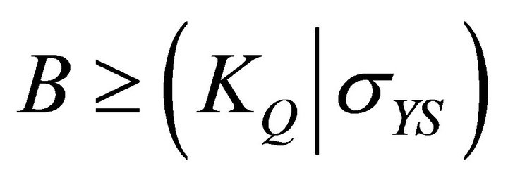
These tests are usually performed in accordance with ASTM E399 (Equation (1)). This test method determines the plane strain fracture toughness (KIc) of the materials. This test is very stringent and a valid test has to satisfy several criteria regarding specimen’s thickness, crack length, and crack length to weight ratio. According to ASTM E399-72 (a/W) is to be within 0.40 ≤a/W ≤ 0.70, and based on the standard, the specimens thickness (B) must be greater than half of the width thickness (W).
Additionally, the test must be in plane strain condition, as plane stress and plane strain conditions vary based on thickness. But the (a/W) ration in this work is just below 0.4. Therefore the data in the tables and figures cannot be used to evaluate the fracture toughness of the material and could only be used for comparison purposes between base metal and zinc galvanized same material.
2.2. Zinc Galvanizing
Test pieces were cleaned with acetone at room temperature, air dried and zinc galvanized by immersion into an industrial zinc bath set up and in use for galvanizing a continuous strip. The bath temperature was about 454.4˚C (850˚F). Each test piece was held in the hot bath
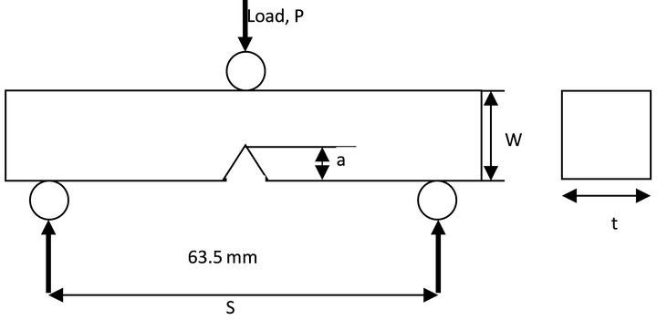
Figure 2. Typical loading configuration and the dimensions of the test specimen.
for a while (about 6 - 8 minutes) to enable sample temperature get to bath temperature.
Flexural 3-point bend tests were conducted on these specimens using a 100 kN load cell equipped with a MTS 810 servo hydraulic material testing system and controlled using MTS TestStar IIs software. The displacement controlled mode was operated with a rate of 0.02 mm/sec. None of the samples were completely broken in half during the 3-point test.
2.3. Optical Microscopy
Two low carbon materials, one plain and the other coated with zinc (by galvanizing) were mounted on a bakelite biscuit and ground to remove all the coated surface (on one sample) and also remove the dimple (necking on both samples) that had occurred in the fracture region during the three point fracture test. About 5 mm (0.196 inch) of material was removed. The material was ground until a completely flat surface was achieved; the mounted samples were then polished on a rotary polisher using the STRUERS Tegra Force-5 on TegraPol-31 rotary wheel. Polishing was done starting with a 320 grit paper for 1 minute, followed by a 9 µm wet pad for 5 minutes, a 3 µm wet pad for 4 minutes and finally a1 µm wet pad for 1 minute. The polisher was equipped to automatically dispense the appropriate micron size polisher solutions after the 320 grit paper. Each polishing stage was followed by washing the sample in running water and cleaning the sample holder in the Tegra Force-5.
Fractured and polished samples were studied with an optical microscope. Specifically, the Olympus GX51 metallurgical microscope was used to study the microstructural features of these materials before and after zinc coating.
2.4. Scanning Electron Microscopy (SEM) Study
Sample pieces from each chemistry were cut from the bend test specimens to include the notch. One piece of the uncoated and one of the coated with Zn (by galvanizing) were both mounted on a Bakelite biscuit and ground to remove the entire coated surface as already described. Figure 3 shows section of the sample that was cut. Figure 4 shows the samples mounted and sitting in the SEM. Focus was on the fractured sections of the samples. Figure 5 shows a typical fracture area on which attention was focused. The fracture morphology of parent (P) and zinc galvanized (G) materials were further studied using the Hitachi 2400 N SEM and ASPEX SEM.
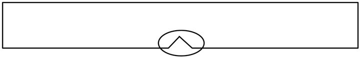
Figure 3. Section of sample that was cut, mounted and used for SEM work.
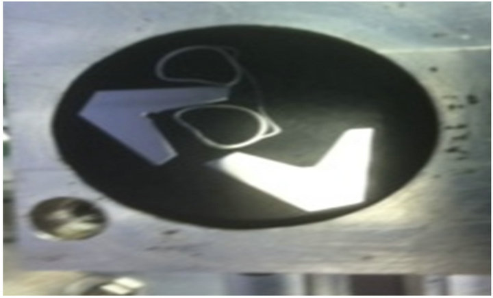
Figure 4. Two “V” shaped samples (one with clip is parent and shiny one is galvanized with coating completely ground off).
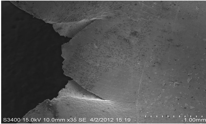
Figure 5. Shows cracked zones of the “V” notch studied for LME cracking.
3. Results and Discussion
3.1. Flexural Behavior of the Parent and Galvanized Low Carbon Steels
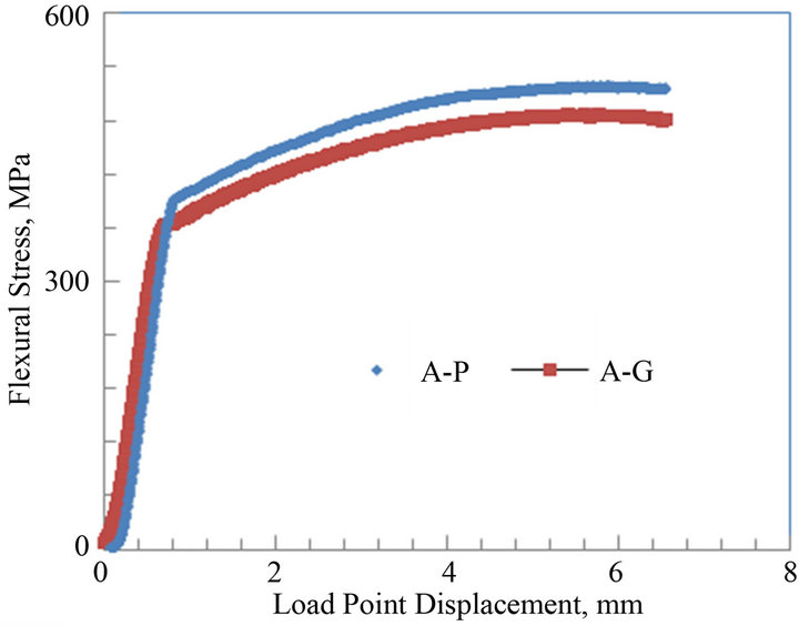
Flexural tests were conducted for both the parent and galvanized low carbon steels on the notched specimens. The plots for flexural stress vs. load point displacement (LPD) for both low carbon steels A and B are shown in Figures 6(a) and (b). The graphs reveal the flexural stress of the notched parent and galvanized low carbon steels A and B. For both parent and galvanized specimens of steels A and B, the graph follows a linear elastic behavior followed by a long non-linear or plastic behavior to failure. The maximum flexural stress of the parent and galvanized low carbon steel A were about 520 and 490 MPa, respectively. For the low carbon steel B, the maximum flexural stress was about 475 for parent and 455 MPa for galvanized, respectively. There was a decrease of 6% in the flexure stress for galvanized steel specimen A when compared to the parent. The flexural stress for the galvanized steel sample B had a decrease of about 4% when compared to the parent sample.
The fracture toughness of the flexural three point bend specimen is calculated based on a general expression. This is used to compare the fracture toughness of the parent and galvanized steel samples. The expression is given as:
 (a)
(a)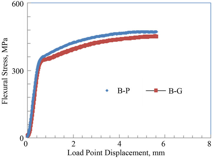 (b)
(b)
Figures 6. Average flexural stress versus load point displacement curves of parent and galvanized low carbon steels: (a) Plate thickness = 9.8 mm; (b) Plate thickness = 6.4 mm.
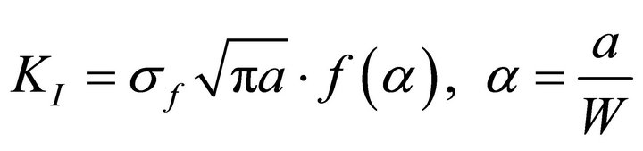 (2)
(2)
where a is the crack length, σf is the residual strength and f(a/W) is a geometrical correction factor. The geometrical correction factor, f(a/W), from the above equation, can be expressed as:
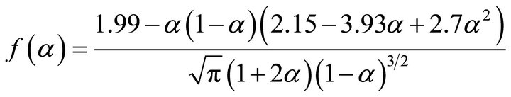 (3)
(3)
In order for the test to be valid for the calculated value 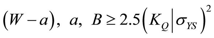 (4)
(4)
 (5)
(5)
However, the specimens’ geometry does not meet the criteria and so the tests fail to be considered as true K1C. The values are therefore considered as apparent fracture toughness KI which were calculated based on the maximum load criteria taken from the fractured specimen.
Table 2 gives the specimen geometry and test results for the parent and galvanized low carbon steels A and B. The average values of KI for the parent and galvanized low carbon steel A were found to be 76 and 71 MPa√m with a standard deviation of ±1.2 and 1.5 MPa√m, respectively. For steel B, the fracture toughness KI values for both parent and galvanized steels were 67 and 63 MPa√m with a standard deviation of ±1.8 and ±1.1 MPa√m, respectively. The toughness values of both galvanized steels A and B showed a decrease of 7% and 6% when compared to their parent counterparts. This shrinkage in the fracture toughness values could be attributed to several possibilities. One known possibility is a result of tensile surface stress created during the hot dipping.
Another reason could be due to the zinc diffusion into the material during the galvanizing treatment, which may have reduced the strength and in turn toughness of the steel samples. A third possibility of hydrogen entrapment has been reported [21].
In hydrogen entrapment it is rationalized that during the hot galvanizing, hydrogen ejected from the steel is held in by the zinc coating. Zinc hot–dip coatings entrap hydrogen at the elevated temperature of the zinc bath 454˚C - 465˚C (~850˚F - 870˚F). It is been proposed [14,21,22] that hydrogen is released from traps during hot-dipping and prevented from escaping by the intermetallic layers that form on the steel surface during coating in the hot bath. The room temperature solubility of 1 atmosphere hydrogen in iron is small, only 8 × 10⁻⁴ ppm. Commercial steels generally contain 0.5 to 5 ppm of hydrogen without any embrittlement; most hydrogen contained in ordinary steel must therefore exist in some chemically combined (trapped) form where it does no harm. This is supported by the fact that delayed failure can be caused by hydrogen concentrations of less than 2 × 10⁻¹ ppm.
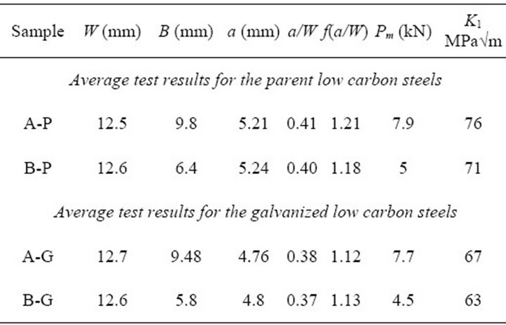
Table 2. Average bend test specimen geometry and test results for low carbon parent and galvanized steels.
3.2. Flexural Behavior of the Parent and Galvanized Medium Carbon Steels
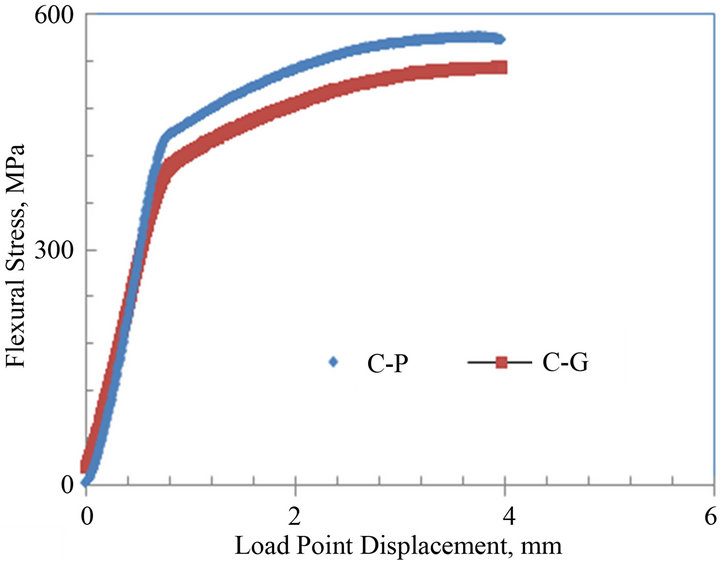
The average flexural stress vs. load point displacement curves of the notched parent and galvanized medium carbon steels C and D are shown in Figures 7(a) and (b). The curves of both steels C and D show both elastic regions followed by plastic or non linear portions representative of ductile fracture. For steel C, the maximum flexural stress for the parent and galvanized specimens were about 575 and 535 MPa, respectively. For steel D, the maximum flexural stress for both parent and galvanized specimens were about 520 and 490 MPa, respectively. The flexural stress for the galvanized specimens had a decrease of about 7% and 6% when compared to their parent counterparts, respectively.
The sample geometry and the average test results for the different specimens tested using the flexural bend test
 (a)
(a)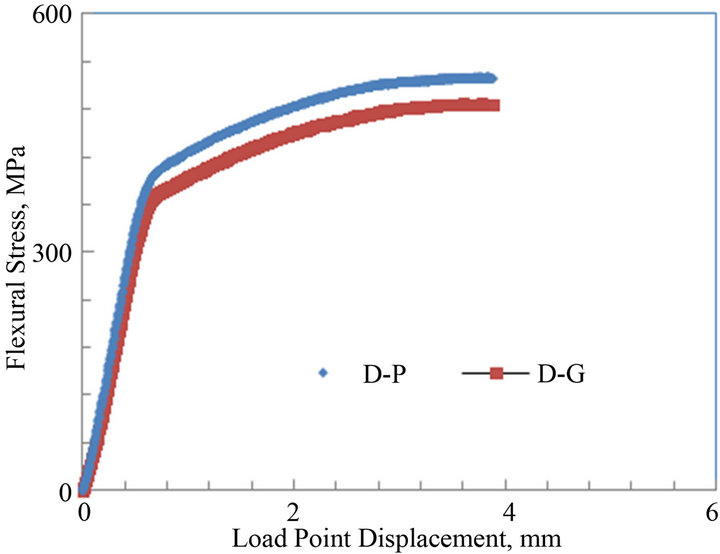 (b)
(b)
Figure 7. Average flexural stress versus load point displacement curves of parent and galvanized medium carbon steels: (a) Plate thickness = 13 mm; (b) Plate thickness = 9.8 mm.
are shown in Table 3. From the table, it can be noticed that the average KI for the parent sample was 84 ± 1.9 MPa√m and 74 ± 2.4 MPa√m for the galvanized. For steel D, the average KI for both parent and galvanized steel specimens were 81 ± 1.1 MPa√m and 70 ± 0.9 MPa√m, respectively. These indicate a decrease of about 12% and 13% in the fracture toughness values of galvanized steels when compared to the uncoated (parent) medium carbon steels C and D. This reduction in the toughness values could be attributed to the zinc galvanizing treatment and other phenomena described earlier in discussing Table 2. Boyd and Hyler [21] in their work on hot zinc coated fasteners found that resistance to crack propagation was reduced and they attributed this to hydrogen phenomenon. This work did not look into hydrogen contribution; it does take a look at the contribution of embrittlement due to zinc and zinc bath alloying elements. Consequently sections of cracked samples were studied under the SEM to find any zinc or zinc bath additives that may have diffused into the cracked zones and so reduced resistance to fracture toughness. Poag and Zervoudis [6] had found that several zinc bath additives were associated with cracking in steel to varying degrees.
3.3. Microstructural Analysis of Low and Medium Carbon Steels (Parent and Galvanized)
The microstructural analysis of the parent and galvanized low carbon steels were done using an optical microscope. The micrographs of the parent low carbon steels A and B taken in the longitudinal direction at 100X magnification are shown in Figure 8. It was found that the low carbon steels A and B showed similar phases in the microstructure. The predominant phase was ferrite, with smaller amounts of pearlite. Steel A seemed to have larger ferrite grains than steel B. The volume fraction of bainitic pearlite increased vice versa (more in B than A).
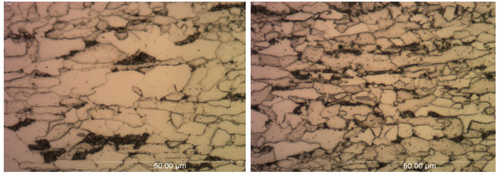
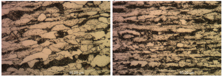
Figure 9 shows the optical micrographs of the parent medium carbon steels C and D taken in longitudinal directions at 100X magnification. These micrographs are
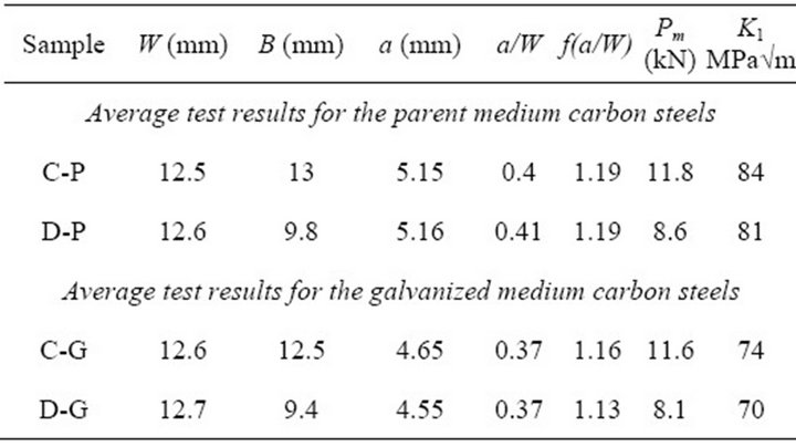
Table 3. Average bend test specimen geometry and test results for medium carbon parent and galvanized steels.
 (a) (b)
Figure 8. Optical micrographs of parent low carbon steels (a) A and (b) B taken in longitudinal direction at 100× magnification.
 (a) (b)
Figure 9. Optical micrographs of parent medium carbon steels (a) C and (b) D taken in longitudinal direction at 100× magnification.
typical ferrite and pearlitic structures. Steel C shown in Figure 9(a) reveals a larger ferrite phase than steel D, which is shown in Figure 9(b). Steel D has a finer grain structure.
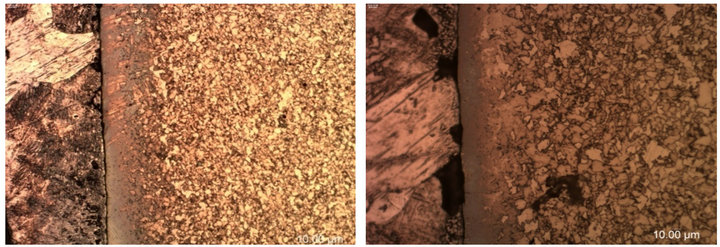
The micrographs of galvanized low carbon steels A and B taken at the notched location are shown in Figure 10. These micrographs show that both steels had dull grey appearance in the middle where the fusion of zinc into the steel occurred. Yeomans [23] explained the dull gray appearance as the result of zeta crystals having grown to the outside of the zinc coating and consuming the pure zinc layer. The coating is non-uniform, poorly adherent and also brittle in nature, as previously reported by Kinstler [13].
3.4. Sensitivity to Liquid Metal Embrittlement
A closer look at the actual differences in the reduction of fracture toughness (KI) between the lower carbon (6% - 7% reduction) and medium carbon steels (12% - 13% reduction) seems to suggest that the lower carbon equivalent (CeV 0.38) of the one could account for the smaller loss of fracture toughness. A research study by Abe [24] established an index of susceptibility for liquid metal embrittlement and suggested a correlation between steel chemistry and zinc bath temperature. Abe et al. suggest a mathematical relation for the susceptibility index (SLM400) as follows:
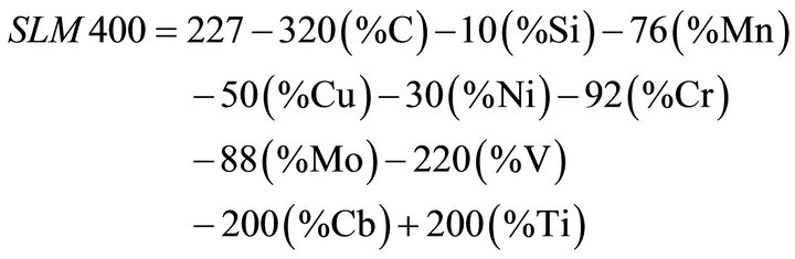 (6)
(6)
 (a) (b)
Figure 10. Optical micrographs of the galvanized low carbon steels (a) A and (b) B taken near the notch location at 20× magnification.
The lower the value of SLM400, the higher the probability a crack will occur during hot dip galvanizing. For ASTM A572 Gr 65 material used in this study and commonly used for transmission structures, an SLM400 value greater than 30 is recommended by Abe et al. [24].The lower the SLM400 number is the higher the chances the material will suffer LME cracking [24]. The low carbon grade in this work has a calculated SLM400 value between 38 and 52, while that of the medium carbon was at about 28. The difference in loss of fracture toughness between the two chemistries could be explained by the SLM400 index.
3.5. SEM Analysis of Parent and Galvanized Low and Medium Carbon Steels
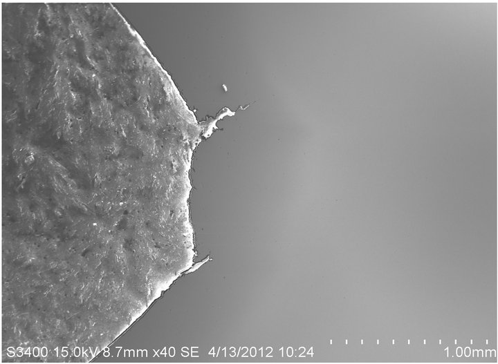
SEM micrographs of the crack regions from the 3-point bend testing for both parent and galvanized low carbon steels are shown in Figure 11. The fracture behavior of the parent sample is shown in Figure 11(a). It shows little crack tip propagation. Figure 11(b), however, obtained for the zinc coated piece, shows a longer crack tip travel on the lower right hand corner and a broader crack opening for the top right hand side. This might be due to the zinc galvanization.
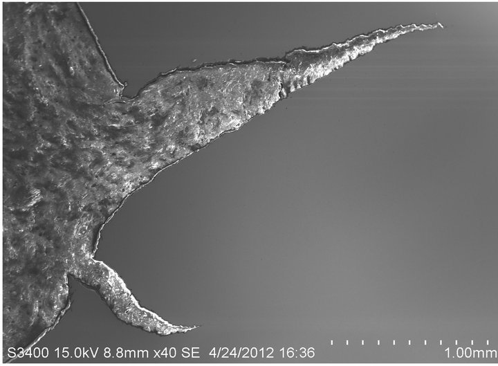
Figure 12 shows micrographs of similar crack region for parent and galvanized medium carbon steel. The galvanized steel micrograph from Figure 12(b) shows more of a contracted crack, or compressed crack, behavior than the parent sample from Figure 12(a). The crack from the parent sample, however, is more relaxed and open. This might be due to the aging response on the surface of the material, where the material behavior is brittle in nature at the surface as the bulk of the steel is not embrittled.
3.6. X-Ray Analysis of Galvanized Low and Medium Carbon Steels
Elemental X-ray analysis was performed on the galvanized low and medium carbon steel crack tips to seek any embrittlement prone elements. X-ray analysis was done using the S-3400 N SEM mounted with an INCA x-act gun. INCA software was used to analyze the results. Over 50 different spectra were taken along the notched
 (a)
(a)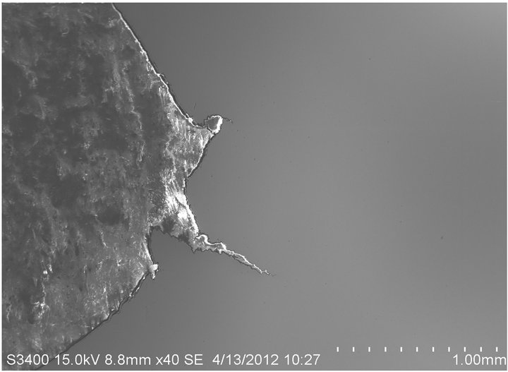 (b)
(b)
Figure 11. SEM micrographs of low carbon (a) parent and (b) galvanized steels showing the cracked region as a result of 3-point bend mechanical test.
and cracked regions to analyze for any presence of zinc and or zinc bath additives. Over 80% of peaks obtained showed clear evidence of presence of zinc as the main constituent element. Other elements such as lead (Pb), antimony (Sb), aluminum (Al), and tin (Sn) were also present. A few typical spectra obtained are shown in Figures 13-16.
3.7. SEM and Elemental Mapping
Using an ASPEX SEM, mounted samples were studied for Zn and Zn bath solution products. Lead (Pb) of up to 1% (Prime Grade, or “PW” zinc) is often found in zinc galvanizing baths. It is a purposeful addition to the bath to enhance drainage of molten zinc to achieve uniform coating. Bismuth (Bi) is also used in place of lead for the same purpose. In recent years tin (Sn) has been found to have such a retarding effect as well. Aluminum is used in zinc baths to enhance “brightness” of the outer zinc coating. It is well known that lead, tin and bismuth have
 (a)
(a)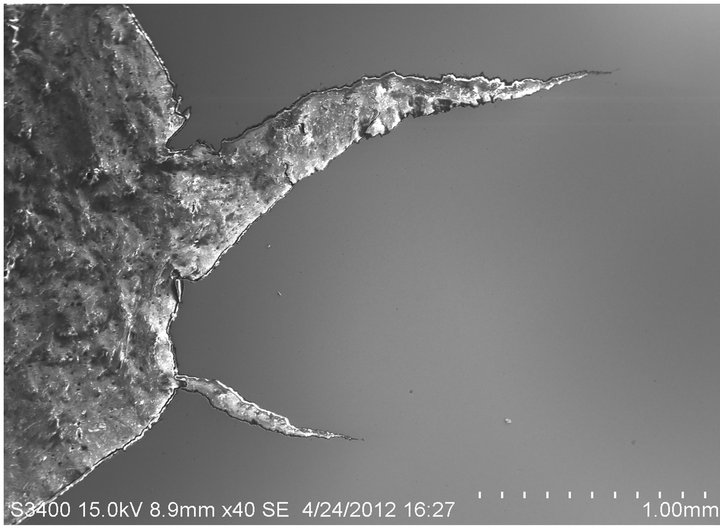 (b)
(b)
Figure 12. SEM micrographs of medium carbon (a) parent and (b) galvanized steels showing the cracked region as a result of 3-point bend mechanical test.
 (a)
(a)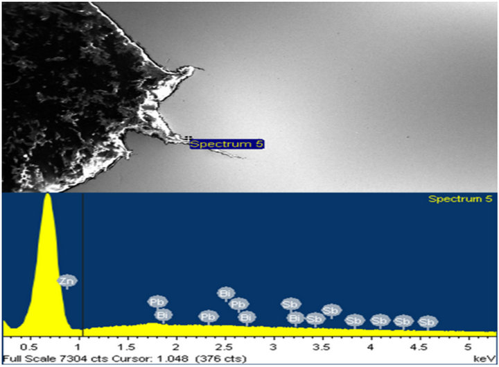 (b)
(b)
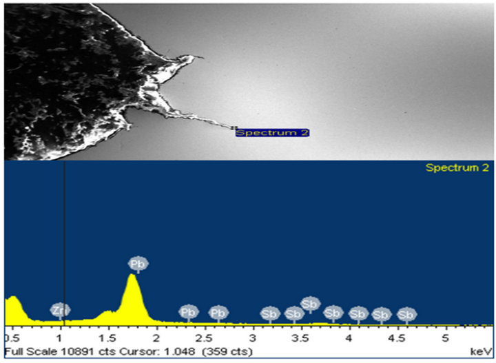
Figure 13. (a) and (b) show the X-ray spectra at locations with Zn, Pb, and Sb peaks around the crack tips.
 (a)
(a)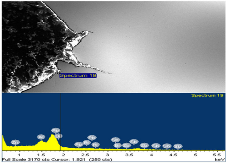 (b)
(b)
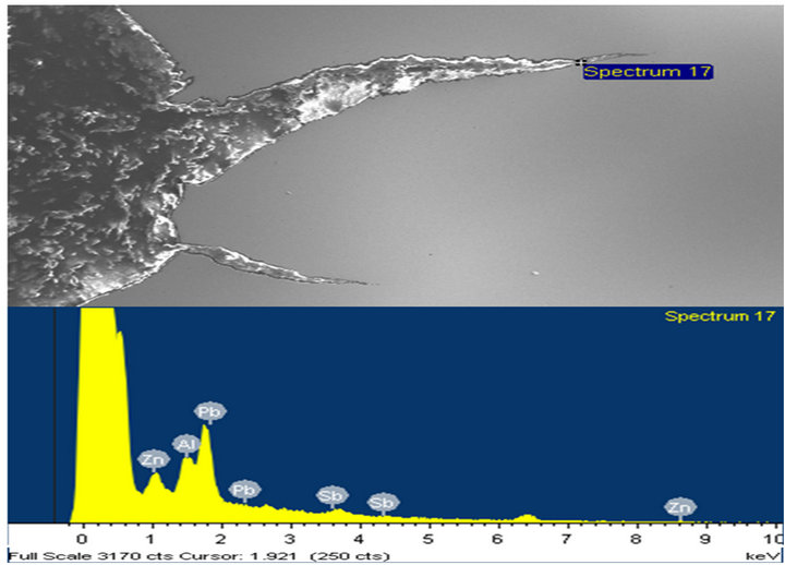
Figure 14. (a) and (b) show the X-ray spectra at locations with more Pb peaks at various points along the crack tip.
 (a)
(a) (b)
(b)
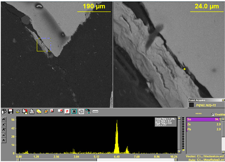
Figure 15. (a) and (b) Show the X-ray spectrums with (a) Sn (94.1), Zn (2.9%) and Pb (2.9%) and (b) Al (41.3%), Zn (34.9%) and Sn (23.9%).
 (a)
(a)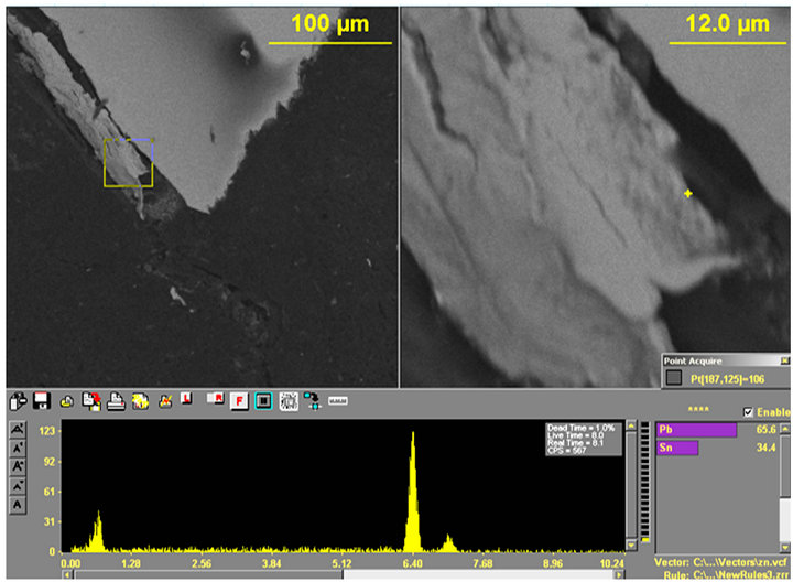 (b)
(b)
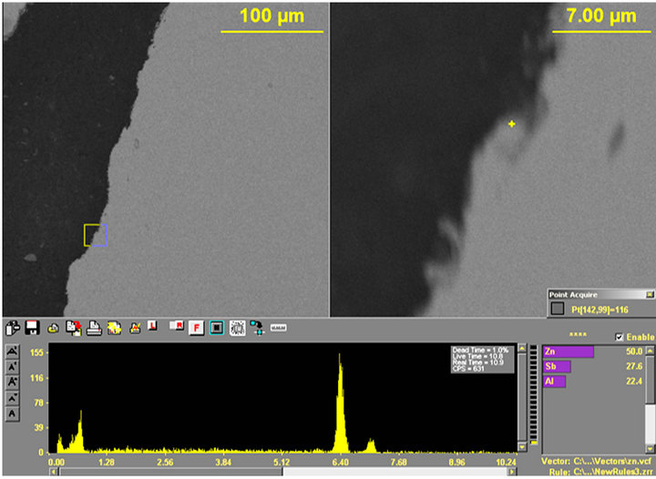
Figure 16. (a) and (b) Show the X-ray spectrums with (a) Zn (50.0%), Sb (27.6%); Al (22.4%) and (b) Pb (65.6%); Sn (34.4%).
lower melting points than zinc.
Consequently the search for the embrittling element often includes these additives which have lower melting pints. Zinc used in North American galvanizing industry follows the ASTM B6 specification and this allows the use of the aforementioned additives.
A brief statement of the mechanism of zinc coating might be pertinent at this stage. In zinc galvanizing, zinc is “consumed” while the typical additives like tin and bismuth are spat out into the bath melt. If zinc enters deformities like an existing crack, void or defect and even a grain boundary in the steel, dilution (spitting out) of the rejected tin and bismuth into the bulk bath is hindered by the distance the metallic additives would have to travel. Consequently the crack or defect will trap these additives. Any detection of the additives therefore gives evidence zinc penetration.
The samples were therefore studied for Bi, Sn, Pb, Sb and Zn. More results are shown in Figures 15 and 16. Notice that several peaks for Sb, Sn, Pb and Zn were found in spite of having thoroughly ground off the coated surface.
The galvanized samples were finally mapped for the said elements as shown in Figure 17. Bright spots indicate the presence and density of such elements present. These findings of several zinc additives in the crack zones are in agreement with the works of several authors [13-27].
3.8. Thermodynamic Considerations—Diffusion
Nicholas et al. [28] showed that preheat temperature affected the adherence of coating (Fe5Si2Al20) on steel substrate and influenced the competitive nucleation and growth kinetics of the adhering phases.
Indeed the authors [28] further reported a decreased interfacial resistance with increase in substrate temperature up to ~450˚C (842˚F). They defined the substrate interface temperature as “the temperature at the time of minimum resistance” and was indicative of the substrate preheat temperature. The authors asserted that the apparent minimum interfacial temperature decreased by an order of magnitude as the temperature was raised from 302˚F - 842˚F (~150˚C to ~450˚C), and thereafter remained constant till about 1112˚F (600˚C). In this work, Zn coating was done at ~850˚F (454.44˚C).
Perhaps the order of magnitude decrease in the apparent minimum interfacial resistance while it resulted in an improved contact of the solid/liquid interface did increase the permeability or diffusivity of the liquid into the solid at those elevated temperatures. In this work zinc and zinc bath additives (Pb, Sn, and Sb) were traced in the cracks. The findings of Nicholas and co-workers [28] confirm that permeation or transport of these elements is thermodynamically possible. Consideration of the kinetics—that is how fast it could occur and also how far the entrapped elements migrated were outside the scope of this work.
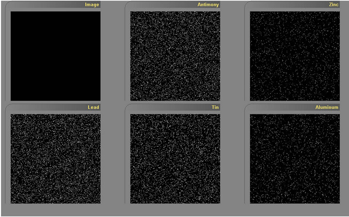
Figure 17. Shows the presence of antimony, zinc, lead, tin and aluminum in the coated but ground and polished sample.
Thermodynamically, Darken [29] demonstrated experimentally that the gradient in chemical potential is the driving force for diffusion. He suggested that the velocity of an atom should be proportional to the force acting on the atom, which in this case is the negative gradient in the chemical potential. He also defined “mobility” as the ratio between velocity and force.
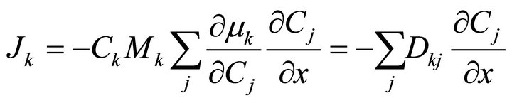
The flux of a component would therefore be written as:
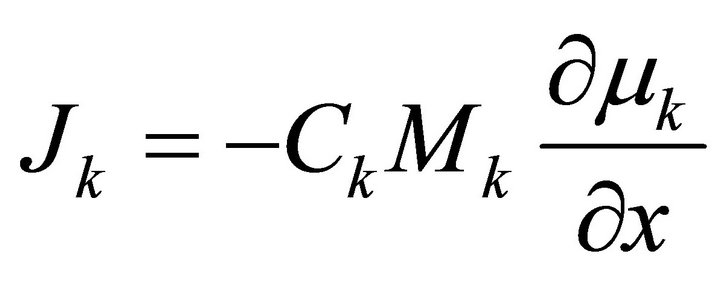 (7)
(7)
where  is the concentration of specie k, (i.e., the number of moles per volume) and µk is the chemical potential of k. Here M is used to denote mobility instead of B used by Darken.
By recalling Fick’s first law and introducing concentration gradient we can write the following for a binary system.
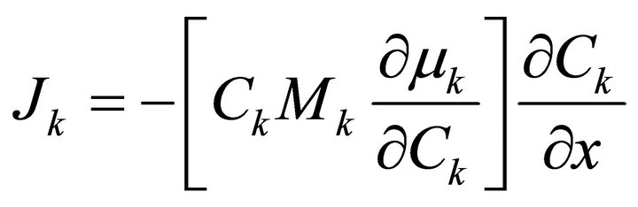 (8)
(8)
For a multi-component system we can write the following.
 (9)
(9)
This requires that we have to introduce several diffusion coefficients to discuss the diffusion of each component. This is the principle of coupling which derives solely from thermodynamic interactions. To overcome this problem some authors (notably, Ågren [30]) have assumed that the variation in mobility M for a specific element in a ternary system is negligible when compared to that element’s mobility in a binary system and can therefore use diffusion data from binary systems to analyze properties for a ternary system.
The purpose of this discussion is to illustrate how the elements Pb, Zn, Bi, Al and Sn picked up in the SEM investigation of our samples (even after 0.2” {~5 mm} of the material was ground off before SEM study) may have migrated to the crack tips. Measurements of diffusivities of those elements in the steel grade used were outside the scope of this study. Even so it becomes clearer that those elements migrated at their own rates (mobilities) at the zinc galvanizing temperatures and eventually contributed to the lower fracture energy reported.
The preceding discussion notwithstanding, it is pertinent to point out that we are aware of previous work [31] to understand the phase transformations that take place at the liquid zinc/steel substrate interface in order to predict and control the microstructure of galvanized coatings. The work acknowledges the difficulty arising from the use of zinc baths with additions of aluminum and substrates that contain deliberately added solute elements to improve substrate steel properties. These difficulties in understanding and the subsequent underlying mechanisms have been best described by Urednicek and Kirklady [32], as related to three main factors 1) Several reactions are occurring at the same time, including (a) wetting of the solid substrate by liquid zinc, (b) dissolution of the steel by the zinc, (c) isothermal solidification of Fe ± Al ± Zn intermetallic compounds, (d) solid state diffusional phase transformations, and (e) solidification of the liquid Zn alloy;
2) The speed of the reactions is very fast and in some cases takes place in less than a second; and 3) The transformation front often becomes unstable and therefore is not governed by simple equilibrium thermodynamics.
Our work has not covered enough ground to dispute these claims, but we agree that thermodynamic considerations are relevant too.
4. Conclusions
A study of liquid metal induced loss of ductility has been completed on two carbon level grade 65 steels.
• The phenomenon is found to affect the steels irrespective of carbon level.
• Lower carbon grade steel lost less (6% - 7%) fracture toughness (KI) than medium carbon steel, which lost 12% - 13%.
• Lower carbon equivalent and higher calculated SLM400 values of the lower carbon steel are suggested to be responsible for the relatively better performance.
• LME seems to follow if stress risers are not removed before steels are zinc galvanized.
• Zinc and associated elements being lower melting elements (than steel) seem to diffuse into the steel at zinc bath galvanizing temperatures.
• Chemical potential difference is suggested to contribute to the driving force for the migration of the embrittling elements.
5. Acknowledgements
The authors wish to thank Nucor Steel Corporation and Tuskegee University for supporting this project through the generosity of Nucor’s NERC Laboratory located at Tuskegee University. The assistance of Mr. Daniel Green of Nucor Tuscaloosa with SEM work and proof reading the material is truly appreciated. The authors wish to thank Nucor Steel Tuscaloosa for supplying the steels used in this study. Kenneth Dawson, undergraduate student in mechanical engineering at Tuskegee University, is acknowledged for assisting in sample preparations.
REFERENCES
- ASTM Standard A123/A123M-09, “Standard Specification for Zinc (Hot-Dip Galvanized) Coatings on Iron and Steel,” ASTM International, West Conshohocken, 2009. doi:10.1520/A0123_A0123M-09
- ASTM Standard A143/A143M-07, “Safeguarding against Embrittlement of Hot-Dip Galvanized Structural Steel Products and Procedure for Detecting Embrittlement,” ASTM International, West Conshohocken, 2007. doi:10.1520/A0143_A0143M-07
- ASTM Standard A385/A385M-11, “Standard Practice for Providing High-Quality Zinc Coatings (Hot-Dip),” ASTM International, West Conshohocken, 2011. doi:10.1520/A0385_A0385M-11
- P. Gordon, “Environmental Sensitivity of Structural Metals: Liquid Metal Embrittlement,” Project Themis, Illinois Institute of Technology, Chicago, 1970.
- R. E. Clegg and D. R. H. Jones, “Liquid Metal Embrittlement in Failure Analysis,” Material Science, Vol. 27, No. 5, 1992. doi:10.1007/BF00726455
- G. Poag and J. Zervoudis, “Influence of Various Parameters on Steel Cracking during Galvanizing,” AGA Tech Forum, Kansas City, October 2003.
- D. G. Kolman, “Liquid Metal Induced Embrittlement,” In: ASM Handbook Vol. 13A, Corrosion: Fundamentals, Testing, and Protection, ASM International, Metals Park, 2003, pp. 381-392.
- R. Steiner, “Properties and Selection: Irons, Steels and High Performance Alloys,” 10th Edition, ASM International, Metals Park, p. 717.
- J. Mandela, “Liquid Metal Embrittlement of Steel with Galvanized Coatings,” Materials Science and Engineering, Vol. 35, 2012.
- V. V. Popovich, “Mechanisms of Liquid Metal Embrittlement,” Material Science, Vol. 15, No. 5, 1980.
- International Lead Zinc Research Organization, “Galvanizing Characteristics of Structural Steel and Their Weldments,” BNF Metals Technology Centre, Wantage, 1975.
- G. Poag and J. Zervoudis, “Influence of Various Parameters on Steel Cracking during Galvanizing,” AGA TechForum, Kansas, 2003.
- T. J. Kinstler, “Research and Update on Galvanized Reinforcing Steel,” Industrial Galvanizers America, Midlothian.
- T. Kinstler, “Cope Cracking Report 5/3/194,” Metalplate Galvanizing Inc., Limited and Internal Circulation.
- T. J. Kinstler, “Current Knowledge of the Cracking of Steels during Galvanizaton,” GalvaScience LLC, AISC, 2005.
- M. Vermeersch, W. De Waele and N. Van Caenegem, “LME Susceptibility of Galvanized Welded Structures of High Strength Steels,” Sustainable Construction and Design, 2001, pp. 442-447.
- W. J. Judd and S. W. Wen, “Failure Mechanisms during Galvanization,” 2008.
- T. Kinstler, “Status Report on the Cracking of Copes in Galvanized Structural Beams,” Metalplate Galvanizing, Inc., Limited and Internal Circulation.
- T. Kinstler, “Cope Cracking Progress Report, 2/1/92 (rev 1),” Metalplate Galvanizing, Inc., Limited and Internal Circulation.
- Project ZM-396, “Control of Cracking in Galvanized Structurals,” Serial Reports Produced by ANMET, Metals Technology Laboratories, Ottawa, 1993-1997.
- J. Robinson, “Predicting the In-Ground Performance of Galvanized Steel,” Mount Townsend Solutions Pty Ltd., March 2005.
- H. E. Townsend, “Effects of Zinc Coatings on the Stress Corrosion Cracking and Hydrogen Embrittlement of Low-Alloy Steel,” Metallurgical and Materials Transactions, Vol. 6A, 1975, pp. 877-883.
- S. R. Yeomans, “Galvanized Steel Reinforcement in Concrete: An Overview,” In: S. R. Yeomans, Ed., Galvanized Steel Reinforcement in Concrete, Elsevier, 2004, p. 320.
- H. Abe, et al., “Study of HAZ Cracking of Hot-Dip Galvanizing Steel Bridge,” IIWDoc. IX-1974-94.
- K. Priestley and J. Carpenter, “Liquid Metal Assisted Cracking of Galvanized Steel Work,” SCOSS—Standing Committee on Structural Safety, London, September 2005.
- W. K. Boyd and W. S. Hyler, “Factors Affecting Environmental Performance of High Strength Bolts,” Journal of the Structural Division—ASCE, Vol. 99, 1973, pp. 1577-1588.
- G. Sedlacek, et al., “On the Reliable Application of Hot Dip Zinc-Coated Steel Beams,” Stahlbau, Vol. 73, 2004, pp. 427-437.
- E. Nicholas, Y. Durandet and L. Strezov, “Dynamic Reactive Wetting and Its Role in Hot Dip Coating,” Metallurgical and Materials Transactions, Vol. 31B, 2000, p. 1069.
- L. S. Darken, “Diffusion of Carbon in Austenite with a Discontinuity of Composition,” Transactions on AIME, Vol. 180, 1949, pp. 430-438.
- J. Ågren, Scandinavian Journal of Metallurgy, Vol. 11, 1982, pp. 3-8.
- A. R. Mader, “The Metallurgy of Zinc-coated Steel,” Progress in Materials Science, Vol. 45, 2000, p. 271.
- M. Urednicek and J. S. Kirkaldy, “Mechanism of Iron Attack Inhibition Arising from Additions of Aluminum to Liquid Zn (Fe) during Galvanizing,” Zeitschrift für Metallkunde, Vol. 64, 1987, p. 649.