Engineering
Vol.6 No.4(2014), Article ID:43807,9 pages DOI:10.4236/eng.2014.64023
Delaware Method Improvement for the Shell and Tubes Heat Exchanger Design
Miguel Toledo-Velázquez1, Pedro Quinto-Diez1, Juan C. Alzelmetti-Zaragoza2, Sergio R. Galvan3, Juan Abugaber-Francis1, Arturo Reyes-León1
1Applied Thermal and Hydraulic Engineering Laboratory SEPI-ESIME-IPN Professional Unit “Adolfo Lopez Mateos”, México DF, México
2Faculty of Mechanical Electrical Engineering, Universidad Veracruzana, Veracruz, México
3Faculty of Mechanical Engineering, Universidad Michoacana de Sán Nicolas de Hidalgo, Edifice H, University City, Santiago Tapia 403, Col. Centro, Morelia, Michoacán, México
Email: mtv49@yahoo.com, arthuro_reyes@yahoo.com.mx
Copyright © 2014 by authors and Scientific Research Publishing Inc.
This work is licensed under the Creative Commons Attribution International License (CC BY).
http://creativecommons.org/licenses/by/4.0/


Received 30 April 2013; revised 30 May 2013; accepted 8 June 2013
ABSTRACT
In this paper the Delaware Method published in 1963 is analized and upgraded with using correction factors which take into account the undesirable currents of the mean flow. However, this method presents graphically these correction factors which imply an impediment to fulfill the software calculations. Thus, the equations corresponding to the correction factor equations and a Fortran 77 numerical program were established. This system is given to explore different design alternatives in order to find the optimal solution to each proposed problem. The results of this work was a simple software that can perform calculations with the introduction of parameters depending only on the geometry of the heat exchanger, i.e., geometry, temperature and fluid characteristics eliminating the human errors and increasing the calculations speed and accuracy.
Keywords:Delaware Method; Flow; Correction Factor; Heat Exchanger

1. Introduction
The method is established in the heat transfer analysis and in the pressure losses of the fluid which flows through the shell side [1] [2] .
In order to complete the heat exchanger analysis, it is essential to consider the different currents generated by the shell side flow, as is shown in Figure 1. This figure has been modified by Palen and Taborek [3] [4] in regard to the original version proposed by Tinker [5] . Here five different streams are identified side of the shell. The current B is known as the mean mixed flow and flows through the mixed flow section and the window section of the heat exchanger. This is the ideal current flowing in the shell side of a heat exchanger.
Besides of flow B, there are four more flows which are present due to the free spaces and cavities between the shell and the deflectors and they provoke a modification of the current B performance.
The different leakages and recirculation currents influence the heat flux transfer in two ways:
1) Reduce the current B resulting in a drop of the heat transfer global coefficient.
2) Modify the shell-side temperature distribution.
The Delaware method considers these effects as correction factors in the heat transfer coefficient and the loss pressure calculations.
The basic equations of the heat exchangers thermal design are:
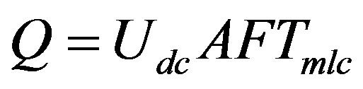 (1)
(1)
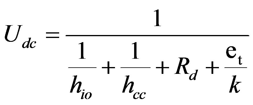 (2)
(2)
In the Equation (2), hcc is the fluid convection coefficient flowing in the shell and it is obtained by Equation (3). In this equation the correction factors are included, the correction factors Ji, Jc, Jl, Jb, Jr,  and Js, which consider the different currents shown in Figure 1.
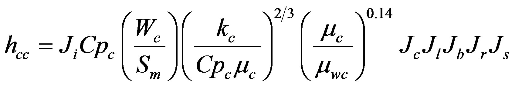 (3)
(3)
For the hydraulic design is required to determine the fluid pressure loss through the shell side and it must be included the correction factors fi, Rb, Rl and Rs. The corresponding calculation is made using the next equation:
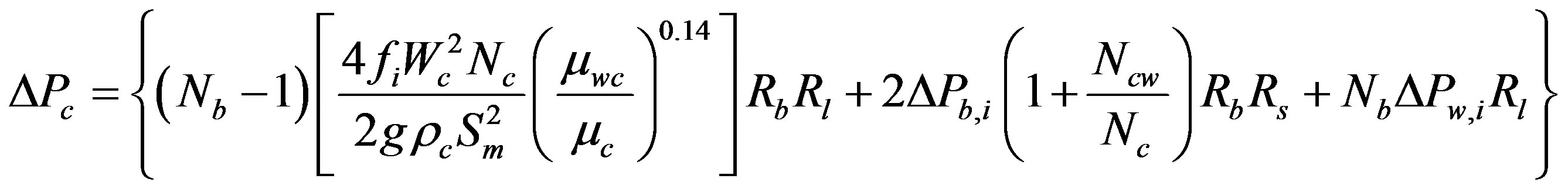 (4)
(4)
It is observed that the principal problem using the Delaware Method is the determination of the eleven correction factors of which nine are obtained graphically. In the next section, the nine correction factors will be presented analytically. The original version only presents analytically the Js and Rs correction factors.
2. Shell Side Correction Factor Equations
According to the Delaware method, after the geometrical parameters computations, the heat transfer and loss pressure are estimated considering the correction factors. This special case will be shown in the next section by using the appropriate Equations [6] -[8] .
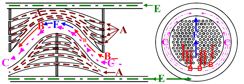
Figure 1. Ideal design of the currents flowing in the shell side. A. Currents flowing through the free spaces between tubes and baffles; B. Mean current flow; C. Recirculation current; D. Leakage current between shells and deflectors; E. Recirculation current in the past partition.
2.1. Correction Factor Ji
This factor depends on the Reynolds Number Rec and the tube arrangement as is established in the next equation:
 (5)
(5)
This equation is applied to the different arrangement tube types: triangular, square, and rhombic. For each case, the constant are presented in Table 1. It was determined 4% as that the maximum error between the equations and the graphic presentation.
2.2. Correction Factor Jc by the Baffle Configuration Effect
The deflector geometry and especially the window cross-section shape provoke currents where the effects are considered in the correction factor Jc. This factor is determined in a mathematical way as following:
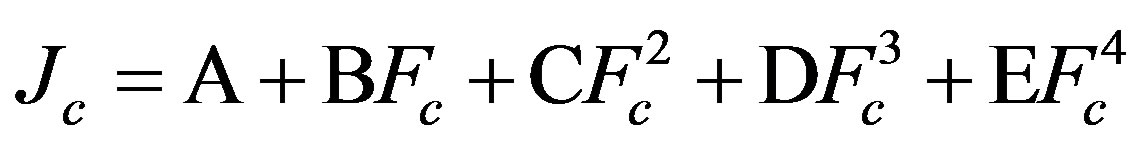 (6)
(6)
The values of each constant are presented in Table 2. Comparing the graphics obtained by Equation (6) and the original one, the maximum error established is 5%.
2.3. Correction Factor by Baffle Leakages Effect, Jl
The fluid that does not exchange heat owing to the leakage through the gap formed by the tubes and the baffles as well as through the shell and baffle is considered in the correction factor Jl. This factor is obtained using the Equation (7) where:

The constants required by this equation are available in Table 3. Comparing the original graph against that one getting by Equation (7), the maximum error is 2%.
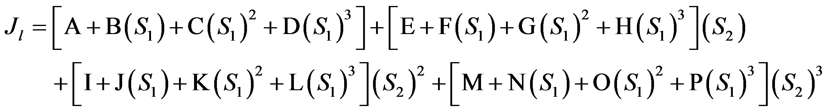 (7)
(7)

Table 1. Constants for the equation for the correction factor Ji.
Table 2. Constants for the equation for the correction factor Jc.
Table 3. Constants for the equation for the correction factor Jl.
2.4. Correction Factor by Recirculation Flow Effect, Jb
The recirculation currents do not exchange heat through the tubes and this issue is considered by the correction factor Jb. This factor is computed by Equation (8) which is based on Fsbp. The constant of the Equation N2 = Nss/Nc are defined in Table 4 in terms of Rec.
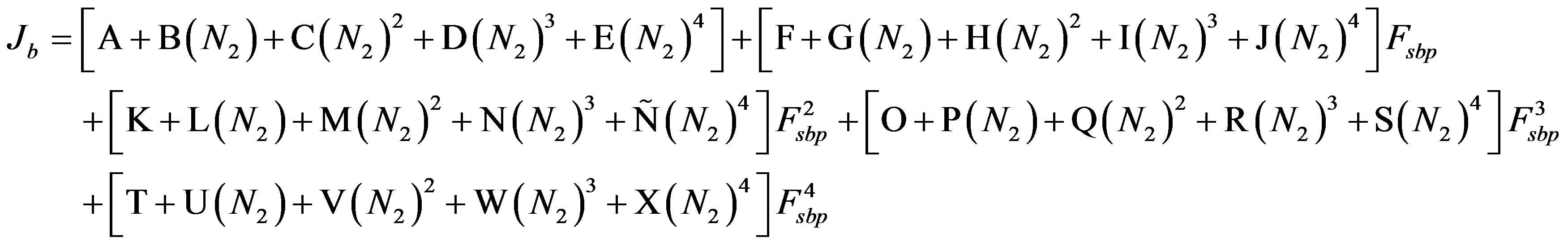 (8)
(8)
A maximum error of 1.3% is result of comparing the original graph against that one obtained by Equation (8).
2.5. Correction Factor by Adverse Temperature Gradient Jr
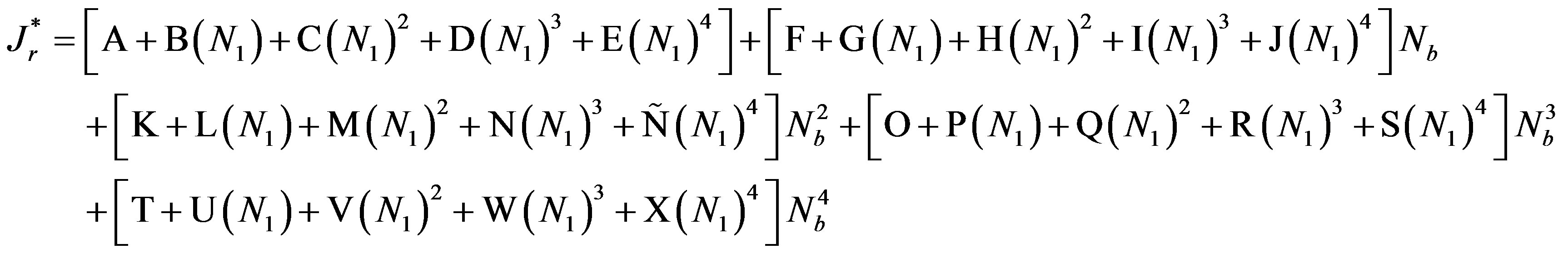
This factor has the value of 1 if Rec ³ 100. When Rec fluctuation is between 0 and 100, the next criterion is used:
1) If Rec £ 20, Jr will acquire the same value as  using the Equation (9), and knowing that Nb and N1 = Nc + Ncw are constants which are shown in Table 5.
 (9)
(9)
A maximum error of 1.9% is result of comparing the original graph against that one obtained by Equation (8).
2) If 20 £ Rec £ 100, Jr is computed by Equation (10) which depends on , Rec and Table 6 constants.
Table 4. Constants for the equation for the correction factor Jb.
Table 5. Constants for the equation for the correction factor .
.
Table 6. Constants for the equation for correction factor Jr.
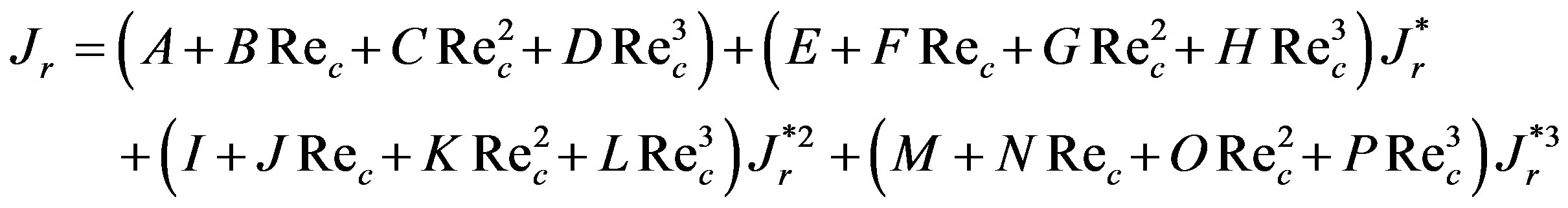 (10)
(10)
In the previous equation,  is calculated by Equation (9). Comparing both graphics, the original and that one obtained by Equation (10), it is observed as maximum error 3.8%.
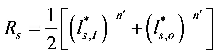
2.6. Correction Factor by Uneven Baffle Spacing at the Inlet and/or Outlet, Js
This factor has an effect when exist a different baffle distribution at the inlet and/or outlet and along the tube bundle and it is computed by Equation (11):
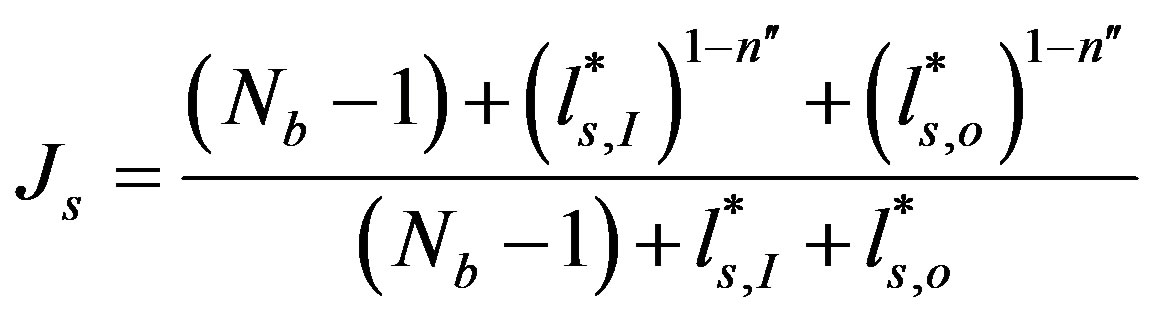 (11)
(11)
where  = 0.6 for turbulent flow and (Rec > 100).
 = 1/3 for laminar flow and (Rec < 100).
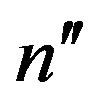
2.7. Correction Factor by Friction of an Ideal Bank Tubes fi
The correction factor by friction in a triangular and rotated square set is determined in function of Rec and the constants presented in Table 7 by the Equation (12).
 (12)
(12)
A maximum error of 4.9% is result of comparing the original graph to that one obtained by Equation (12).
2.8. Pressure Loss Correction Factor by Tube-Baffle Leakage Rl
The introduction of this correction factor is due to the leakage of the tube bundle and it is computed by Equation (13) which is in terms of  and
and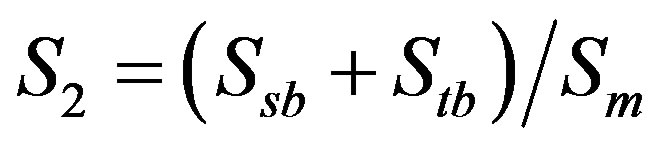 .
.
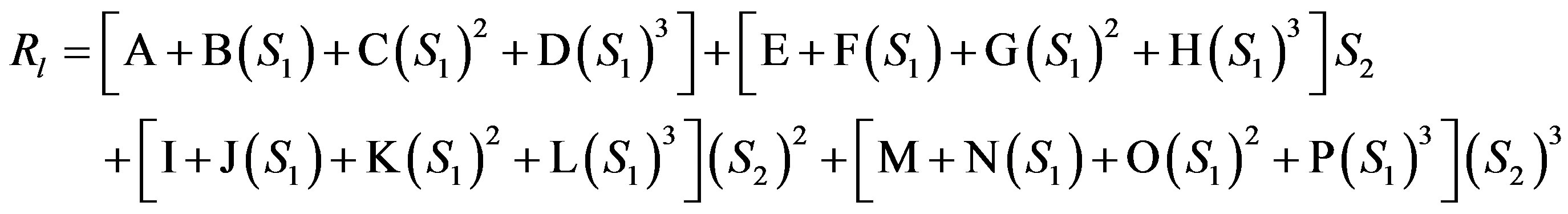 (13)
(13)
The constants required by the equations are established in Table 8. Comparing the original graph and that one obtained by Equation (13) is observed a maximum error of 4.5%.
Table 7. Constants for the equation for the correction factor fi.
Table 8. Constants for the equation for the correction factor Rl.
2.9. Pressure Loss Correction Factor by Recirculation Effect Rb
This correction factor is provoked by circulation currents in the heat exchanger and it is computed by Equation (14) which is in terms of Fsbp and N2 = Nss/Nc.
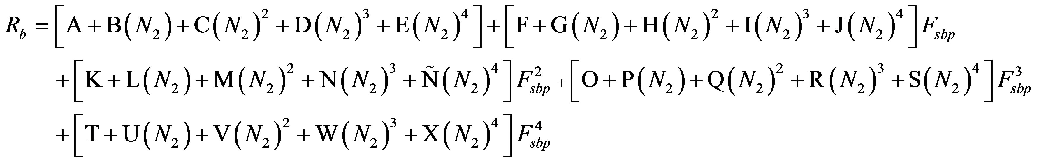 (14)
(14)
The constants demanded by the equation are defined in Table 9 and they are in terms of Rec number. Comparing the original graph and that one obtained by Equation (14), the maximal error found is 1.3%.
2.10. Pressure Loss Correction Factor by Uneven Baffle Spacing at the Inlet and Outlet
This correction factor is proposed by the uneven baffle spacing at inlet and outlet of the heat exchanger and this factor is calculated by Equation (15).
 (15)
(15)
where  = 1.6 for turbulent flow (Rec > 100).
 = 1 for laminar flow (Rec < 100).
3. Calculus Program
Having the correction factors in an analytical form, it was developed a calculus program using the FORTRAN 77 language which will design quickly the shell and tubes heat exchanger through the improvement DELAWARE Method. This computing program is described next:
Flow Chart Program
The flow chart used for the shell and tubes heat exchanger is presented in Figure 2.
As from this flow chart, it was made the heat exchanger design program using the executable BELL since it runs in MS DOS platform.
4. Conclusions
This work has presented the improvements to the Delaware method for the shell and tube heat exchanger design. These improvements were made up not only of obtaining the correction factor equations which were only available in graphic forma but also of developing the computing program in Fortran 77 language.
Thus, a new and easy tool for the shell and tubes heat exchanger design is available which allows accomplishing the numerical computing in a quick form minimizing the errors of the graphical lecture. This system gives the opportunity to explore different design alternatives in order to find the optimal solution to each proposed problem.
Recent years, heat exchanger is often used for the request of technology. But the relevant design is not provided by the actual standards. This work presents the improvements to the Delaware method for the shell and
Table 9. Constants for the equation for the correction factor Rb.
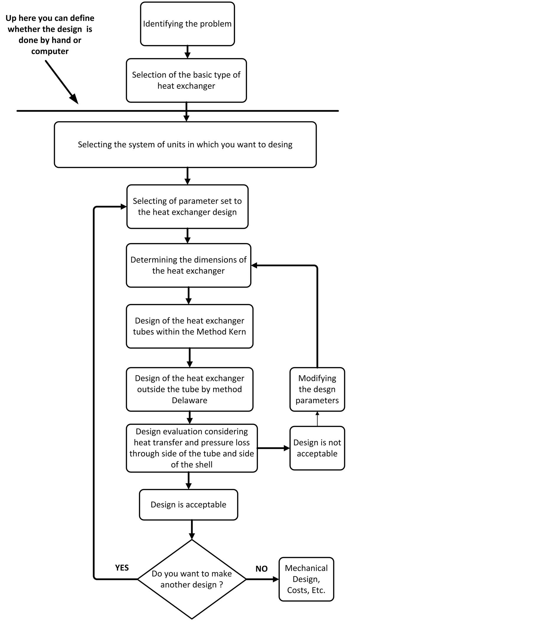
Figure 2. Flow chart program.
tube heat exchanger design.
References
- Vengateson, U. (2010) Design of Multiple Shell and Tube Heat Exchangers in Series: E Shell and F Shell. Chemical Engineering Research and Design, 88, 725-736. http://dx.doi.org/10.1016/j.cherd.2009.10.005
- Costa, A.L.H. and Queiroz, E.M. (2008) Design Optimization of Shell and tube Heat Exchangers. Applied Thermal Engineering, 28, 1798-1805. http://dx.doi.org/10.1016/j.applthermaleng.2007.11.009
- Serna, M. and Jimenez, A. (2005) A Compact Formulation of Bell-Delaware Method for Heat Exchanger Desing and Optimation. Chemical Engineering Research and Desing, 83, 539-550. http://dx.doi.org/10.1205/cherd.03192
- Shah, R.K., Dusan, P. and Sekulic, D.P. (2003) Fundamentals of Heat Exchanger Design. John Wiley & Sons, Hoboken. http://dx.doi.org/10.1002/9780470172605
- Ayub, Z.H. (2005) A New Chart Method for Evaluating Single-Phase Shell Side Heat Transfer Coefficient in a Single Segmental Shell and Tube Heat Exchanger. Applied Thermal Engineering, 25, 2412-2420. http://dx.doi.org/10.1016/j.applthermaleng.2004.12.015
- Leong, K.C., Toh, K.C. and Leong, Y.C. (1998) Shell and Tube Heat Exchanger Design Software for Educational Applications. International Journal of Engineering Education, 14, 217-224
- León, A.R., Velazquez, M.T. and Diez, P.Q. (2011) The Design of Heat Exchangers. Engineering, 3, 911-920.
- Castillo, R. (1999) Diseño Computacional de Intercambiadores de Calor de Coraza y Tubos por el Método Delaware. Tesis de Maestría, Instituto Politécnico Nacional, México.
Nomenclature