Engineering
Vol.4 No.11(2012), Article ID:24526,4 pages DOI:10.4236/eng.2012.411095
Numerical Study on an Applicable Underground Mining Method for Soft Extra-Thick Coal Seams in Thailand
Department of Earth Resources Engineering, Kyushu University, Fukuoka City, Japan
Email: nayzarlin@mine.kyushu-u.ac.jp
Received August 1, 2012; revised September 10, 2012; accepted September 22, 2012
Keywords: Multi-Slice Bord-and-Pillar Method; Soft Extra-Thick Coal Seams; Numerical Analyses; Flac3D
ABSTRACT
The EGAT Mae Moh Mine is the largest open pit lignite mine in Thailand and it produces lignite about 16 million tons annually. In the near future, the pit limit of the mine will be reached and underground mine will then be developed through the open pit in the depth of 400 - 600 m from the surface. However, due to the challenges for underground mining such as poor geological conditions, extra thickness (20 - 30 m) of coal seams, and weak mechanical properties of coal seams and the surrounding rock, the success possibility of underground mining and an applicable underground mining method is being investigated at the present. The paper discusses the applicability of multi-slice bord-and-pillar method for the soft extra thick coal seams in the Mae Moh mine by means of numerical analyses using the 3D finite difference code “FLAC3D”.
1. Introduction
Thick coal seams have been mined by various methods, such as extended height single pass longwall method, longwall top coal caving method, slicing method, blasting gallery method, and hydraulic mining method etc., depending on local geological and geotechnical conditions and thickness, depth and characteristics of seams. Thick seam mining is very different from conventional coal mining in many aspects. It is rather complicated to predict the characteristics of strata response to mining operation and the mining of such seams is beset with numerous problems [1-3]. Although there have been many research works that focused on the thick seams in medium to strong geotechnical conditions, very few researches and publications are found for the extra-thick seams that are over 10 m in thickness in weak conditions. In this study, it investigated the ground response to mining and failure mechanism in soft extra-thick seams by means of numerical analyses and discussed an applicable underground method for mining the soft extra-thick coal seams in Mae Moh mine in Thailand.
2. Brief Information of Mae Moh Mine
2.1. General
Mae Moh mine is located in Mae Moh district, Lampang province, about 630 kilometers north of Bangkok, in Thailand. The location map of Mae Moh mine is shown in Figure 1. This mine is operated by EGAT (Electricity Generating Authority of Thailand), and it is the largest open-pit lignite mine in Thailand. The total geological and economical lignite reserves are approximately 1140 million tons and 825 million tons, respectively. The annual production is about 16 million tons, which represents 70% of the total coal production of Thailand. All of the lignite produced from the mine is supplied to the 2400 MW Mae Moh power plant that is providing 15% of the total electricity demand of Thailand. About 347 MT of lignite has been produced, and the remaining future reserve is approximately 478 MT as of 2011.
The current Mae Moh pit covers an area of 4 km by 7.5 km at various depths up to 290 m as of 2011. According to the mining plan reported by the EGAT, the final pit limit will be reached and the open pit operation will be finished in the near future. After that, underground mining will be commenced through the final pit high wall from the depth of about 400 m. The total lignite reserves in the underground mine area are approximated about 150 million tons (see Figure 2). However, due to the adverse geological and geotechnical conditions such as extra thickness of coal seams, and weak mechanical properties of coal seams and the surrounding rock, success possibility of underground mining and an applicable underground mining method for Mae Moh mine is being investigated at the present [4,5].
2.2. Geologic Settings of Mae Moh Mine
Mae Moh mine is situated in Mae Moh tertiary basin
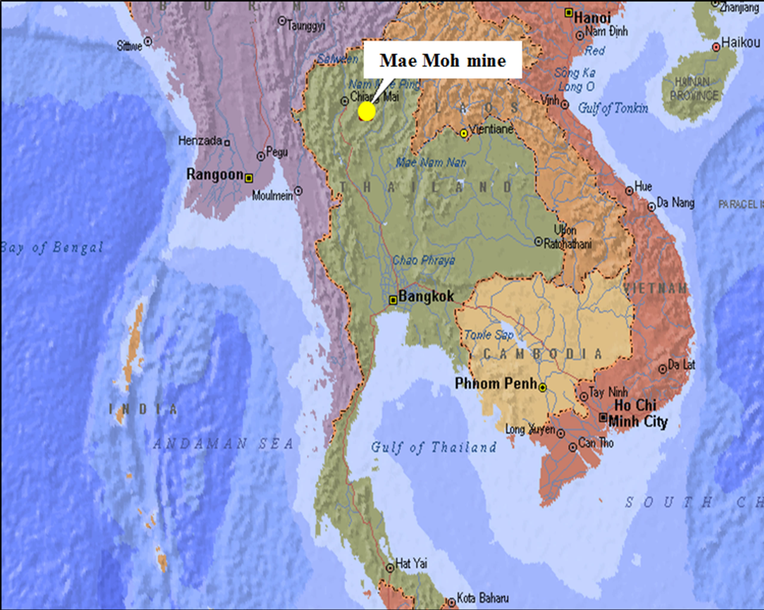
Figure 1. Location of Mae Moh mine.
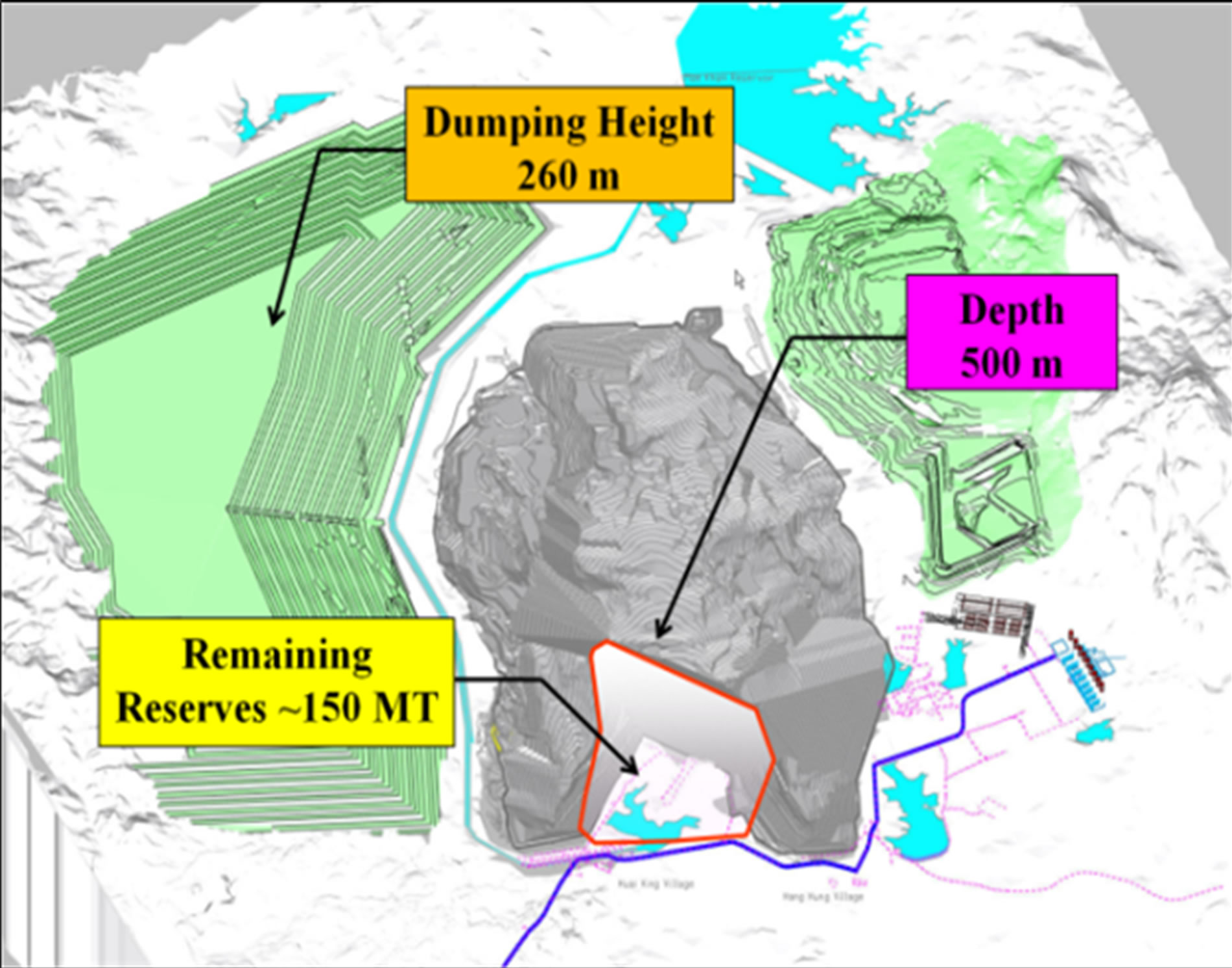
Figure 2. Final pit of Mae Moh mine (plan).
which is more than 1000 m of maximum thickness. Three main geological formations, namely Huai Luang (HL), Na Khaem (NK) and Huai King (HK), are found in the Mae Moh basin (see Figure 3). HL formation mainly consists of red to brownish-red semi-consolidated and unconsolidated clay, silt and sandstone. NK formation composes lignite seams and gray to greenish-gray claystone and mudstone, whereas HK formation consists of semi-consolidated fine to coarse sand-stone, claystone, mudstone and conglomerate with green, yellow, blue and purple in color. Five lignite seams, marked as J, K, Q, R and S seam, are found in the NK formation. However, the J, R and S seams are considered uneconomical due to the poor quality/thickness and depth of seam, and thus
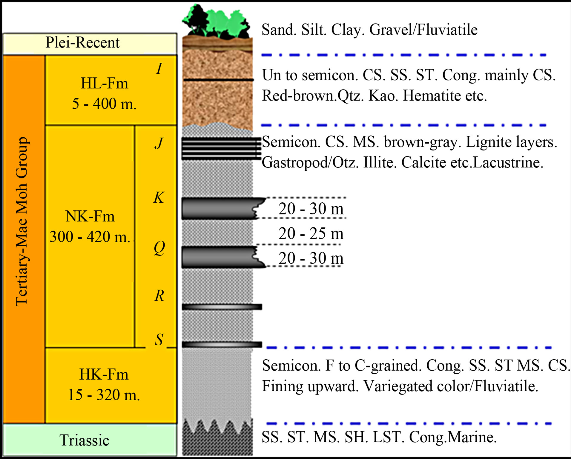
Figure 3. Generalized stratigraphic column.
major economical mineable seams are only K and Q seams. The thickness of K and Q seams ranges from 20 to 30 m with the interburden of 20 to 25 m mudstone, up to 600 m depth from the surface [4,5].
3. Numerical Modeling
In underground mining of a coal seam that exceeds 10 m in thickness, extraction is mostly considered as dividing the seam into a number of slices/lifts and extracting each slice/lift with a longwall or bord-and-pillar using continuous or conventional mining methods. In a multi-slice mining, the longwall caving system is the preferred practice; but, the material produced requires a large expense to compensate for surface/subsurface damage. Furthermore, it is possible for nearby seas, lakes, rivers, creeks, canals, and other surface features to be disturbed if serious damage occurs [6,7]. For the Mae Moh mine, however, the application of longwall method in underground mining is considered limited potential since the properties of rocks are very weak and the coal seams are extra-thick, that might occur large ground disturbance/subsidence and thus it is possible to occur the pit instability and many problems. Therefore, the multi-slice bord-andpillar mining was firstly considered in this study and its applicability in soft extra-thick seams was investigated by means of numerical analyses using three dimensional finite difference program Flac3D.
3.1. Description of the Numerical Model
The Flac3D numerical model was composed of 20 m and 25 m thick double coal seams, named as k_seam and q_seam, with the interburden of 25 m and overburden of 400 m in thickness. For simplicity, multi thin layers were not considered and the overburden and interburden were modeled as homogeneous mudstone layers. Due to the limitations of computer running time and capacity restriction, only the upper coal seam, k_seam, was modelled for extraction and set up with a smaller mesh size in order to obtain more precise stress, distribution ground displacement, and failure distribution around the extraction area. The total dimension of the model is 220 m wide, 220 m long and 470 m high, respectively. The numerical model consists of 448,000 elements and 468,671 grid points. The geometry, density of grids and group of materials of the model are presented in Figure 4. The bottom of the model was restricted in the vertical direction, whereas the sides of the model were restrained perpendicular to each side. Mohr Coulomb elasto-plastic constitutive relation was employed in the analyses. The mechanical properties of the materials used in the numerical analyses are presented in Table 1. After defining the constitutive relation and material properties, and assigning boundary conditions and initial state, the model was run until the equilibrium stage had been reached. After the response of the model was satisfactory, formulation of bord-and-pillar mine was conducted by excavation of galleries and formation of pillars sequentially.
3.2. Results and Discussion
At first, the ground response and pillar conditions in different pillar sizes were investigated in order to determine an appropriate pillar size. The width and length of the panel was taken as 100 m in the X direction and 150 m in Y direction. The dimension of each gallery was taken as 6 m in width and 3 m in height, respectively. In the case of Mae Moh coal field where coal seams are soft and

Figure 4. Flac3D numerical model.

Table 1. Mechanical properties of the materials used in the analyses.
extra-thick, multi slicing with ascending order of extraction is considered limited potential as ascending order does not allow caving into the galleries [7]. Therefore, the first slice was modeled along the roof and the next slices were then modeled sequentially in descending order. Figures 5 and 6 show the failure states at different size of pillars after the first slice was developed along the mine roof. The pillar width to height ratio (w/h) is 4 in the Figures 5 and 6 in the Figure 6, respectively. In Flac3D, the terms in legend of figures showing block state “none” indicate no-failure zone, “shear-n” and “tension-n” indicate yield in shear and tension now, “shear-p” and “tension-p” indicate elastic state now, but yield in shear and tension past, respectively [8].
According to the results, it could be seen that all the pillars in the Figure 5 failed (shear-n, tension-n) whereas pillars seemed to be in stable in Figure 6 although partial failures occurred. Therefore, the pillars size was considered starting from the w/h of 6 in the analyses. Figures 7 and 8 show the conditions of pillars, with the w/h of 6, after the second slice was developed in superimposed and non-superimposed pattern, where the coal parting 3 m was left between the slices. According to these results, it was expected pillar instability and roof control problems in both patterns of developments; all pillars and
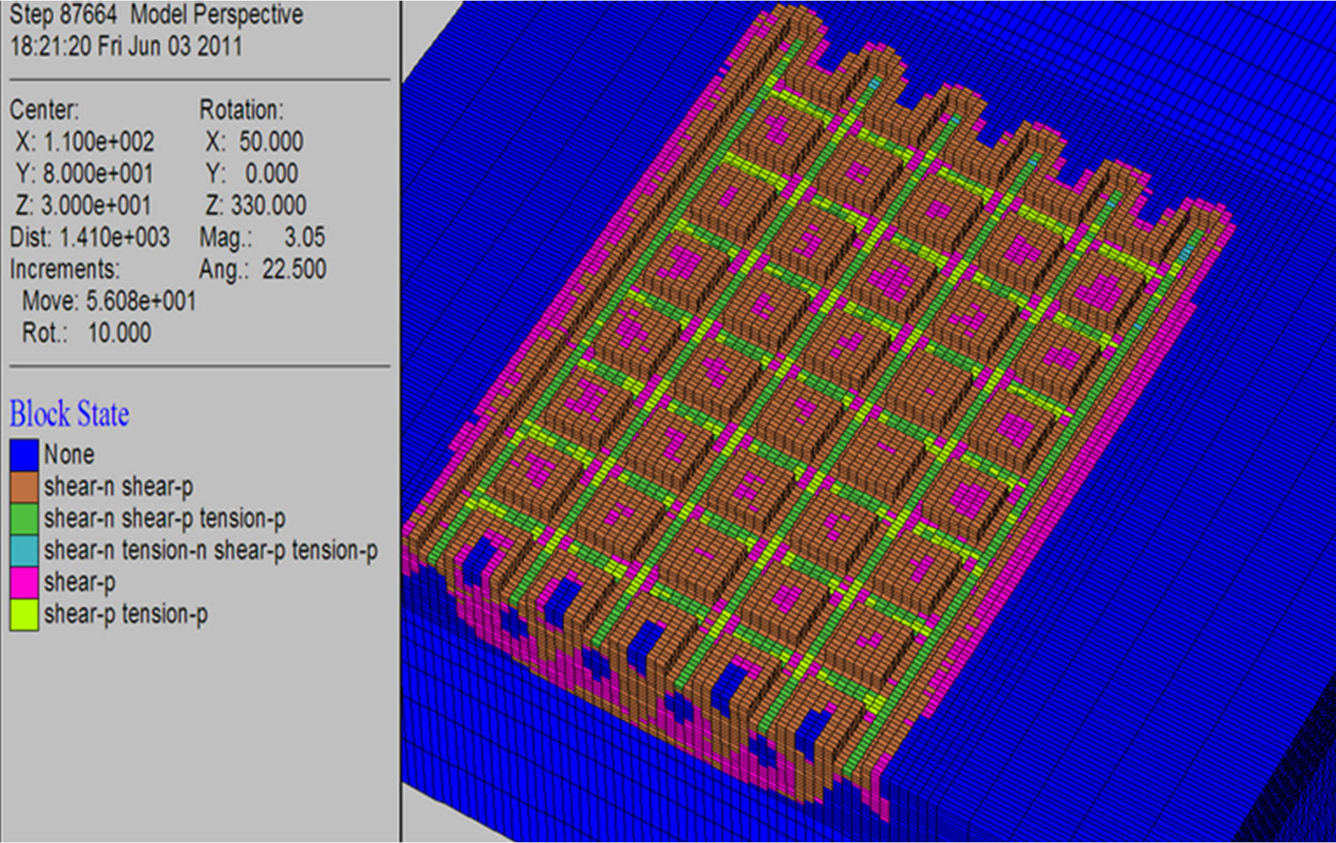
Figure 5. Failure state at pillars after developing first slice along the roof (pillar width of 12 m (w/h = 4)).
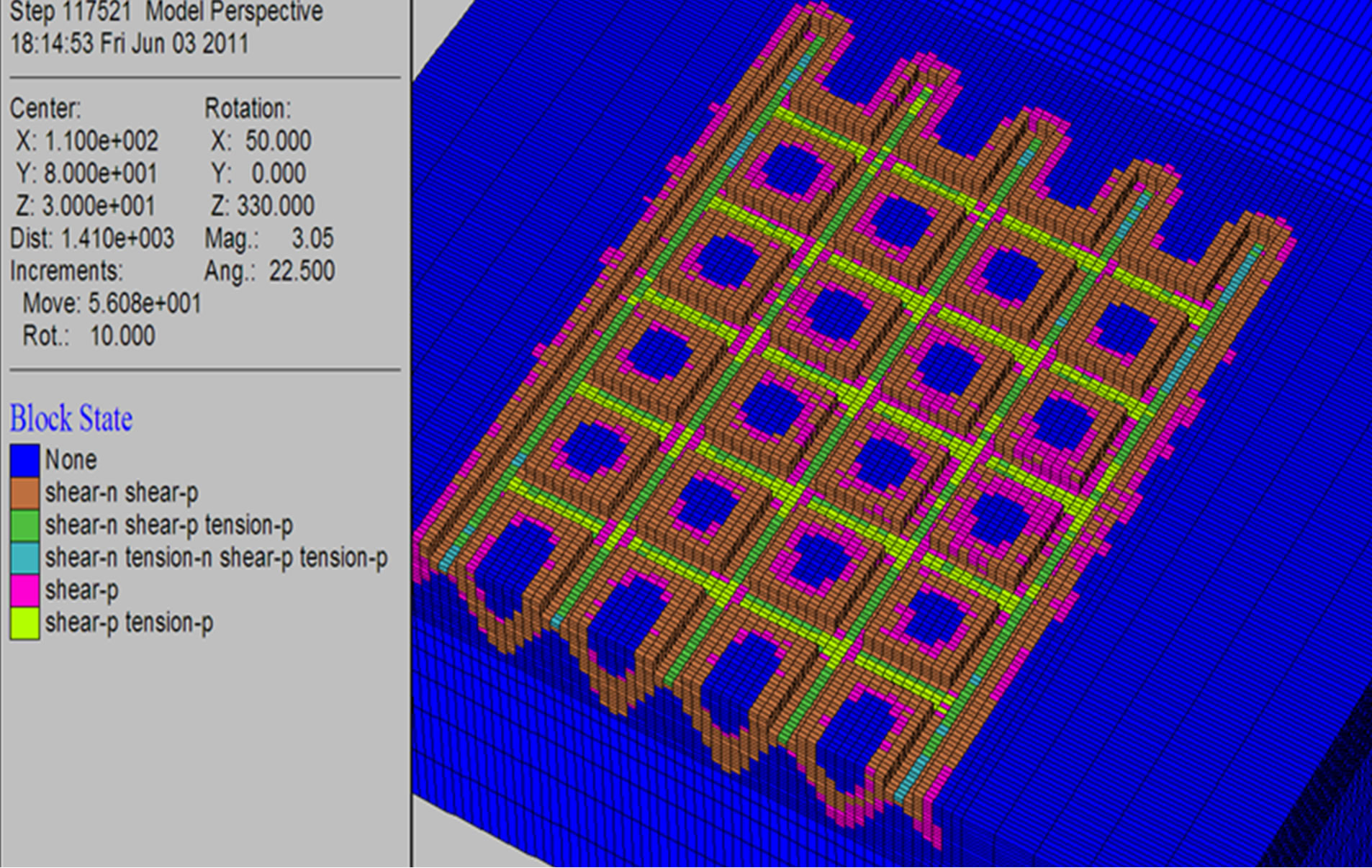
Figure 6. Failure state at pillars after developing first slice along the roof (pillar width of 18 m (w/h = 6)).
parting failed in superimposed pattern development whereas pillars at the first slice and parting failed in nonsuperimposed pattern development. Subsequently, the pillars size and parting thickness were increased and the response was investigated. However, it was found that the conventional multi-slice bord-and-pillar could not be successful in the soft extra-thick seams due to the problems in roof control and failures of partings and openings when the lower slices were extracted.
Due to the situation discussed above, it was investigated the performance of an alternative method in which stowing and different cutting method were employed. The purpose of stowing is not to transmit the rock stresses, but to reduce the relaxation of the rock mass so the rock itself will retain a load carrying capacity and will improve load shedding to crown pillars and abutments. This leads to less deterioration in ground conditions in the mine, improving operations and safety [9]. The required strength of the stowing materials depends on the strata and mining conditions: such as cover depth, rock type and properties, mining method, etc. In a shallow mine, the required strength is not as critical when compared to that for a deep mine. Considering the rock properties at


Figure 7. Failure state after developing the second slice in superimpose d pattern (a) cutting view along the central part of the panel and (b) pillars in the second slice.


Figure 8. Failure state after developing the second slice in non-superimposed pattern (a) cutting view along the central part of the panel and (b) pillars in the second slice.
the vicinity of the production area and the depth of the seams at the mine, the strength of stowing material was initially taken as one half of the coal strength in the study [10-12]. The alternative coal cutting method and stowing were carried out as shown in Figure 9.
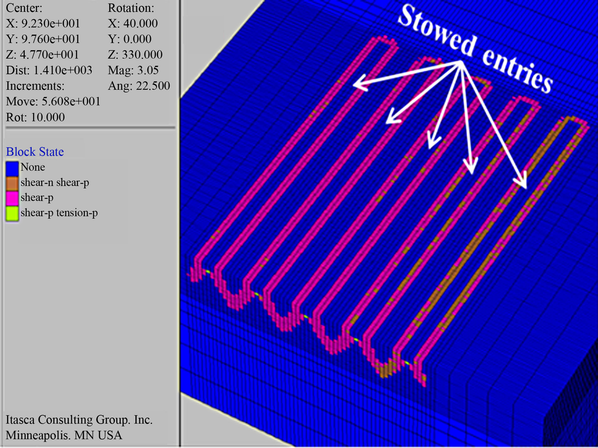
First, pairs of entries were cut across the mine roof by leaving 18 m wide pillars between them (see Figure 9(a)). The width of each entry was also taken as 6 m and mining height was 3 m. After that the cut entries were stowed (see Figure 9(b)) and a pairs of entries were then cut next to the stowed entries (see Figure 9(c)). The mining and stowing were repeated in the same manner until the whole panel was extracted (see Figure 9(d)). According to the results of failure state shown in Figures 9(a)-(d), it was found that the pillars maintained their stability until the whole panel was extracted. The confinement produced by stowing improved the pillars’ stability throughout the panel extraction. Figures 10(a) and (b) show contours of vertical displacement and failure state after cutting pairs of entries at the second slice. According to the results, it was found a very few failures zones (shear-n, tension-n) at the roof and small displacement about 2 - 4 cm in maximum around the openings and therefore, the problems in roof control and pillars failure cannot be expected. Mining and stowing were repeated in the same manner as the first slice. The next slices extractions were also done slice by slice sequentially in descending order and no large roof control and pillars instability problems were expected during the extractions. Figures 11(a) and (b) show contours of vertical displacement and failure state after extracting the whole k_seam. It could be seen that the ground displacement and failures around the extracted seam are very small even after the whole seam was extracted. Therefore, it could be supposed that this is an applicable and effective method for mining soft extra-thick seams in terms of diminishing ground disturbance, mine safety and maximizing coal recovery.
 (a)
(a)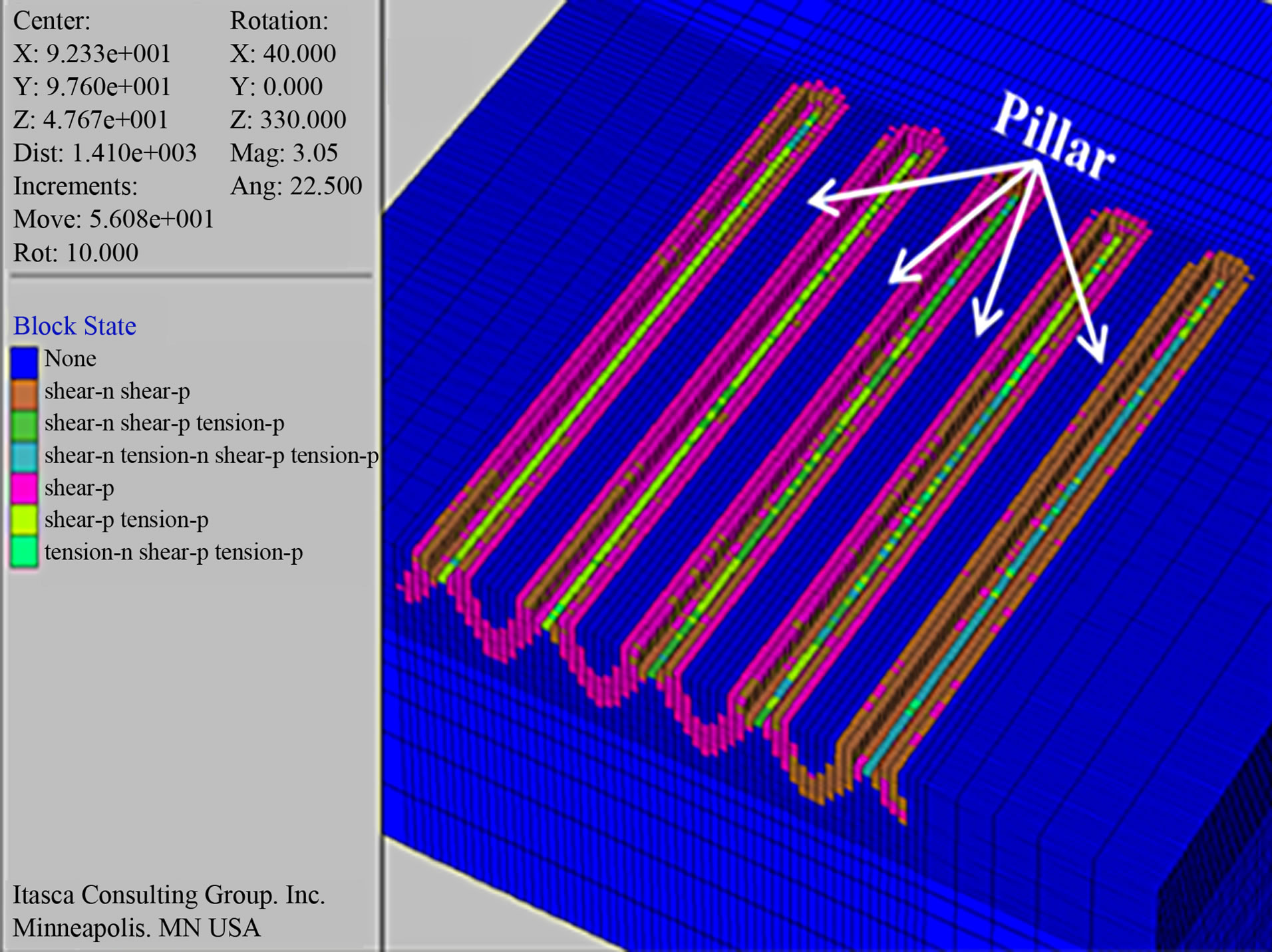 (b)
(b)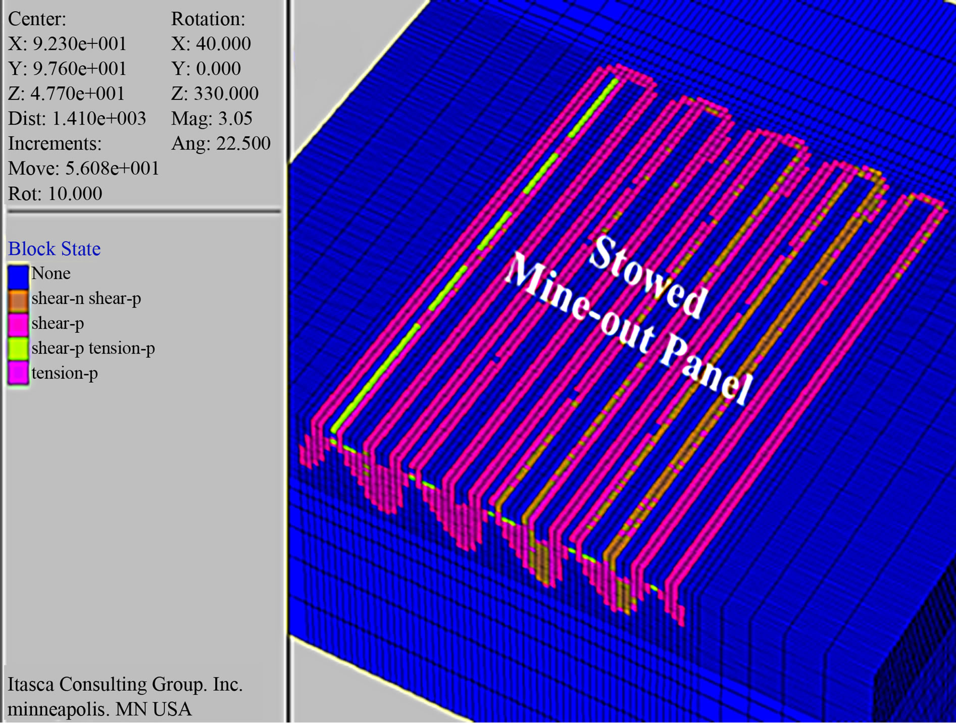 (c)
(c)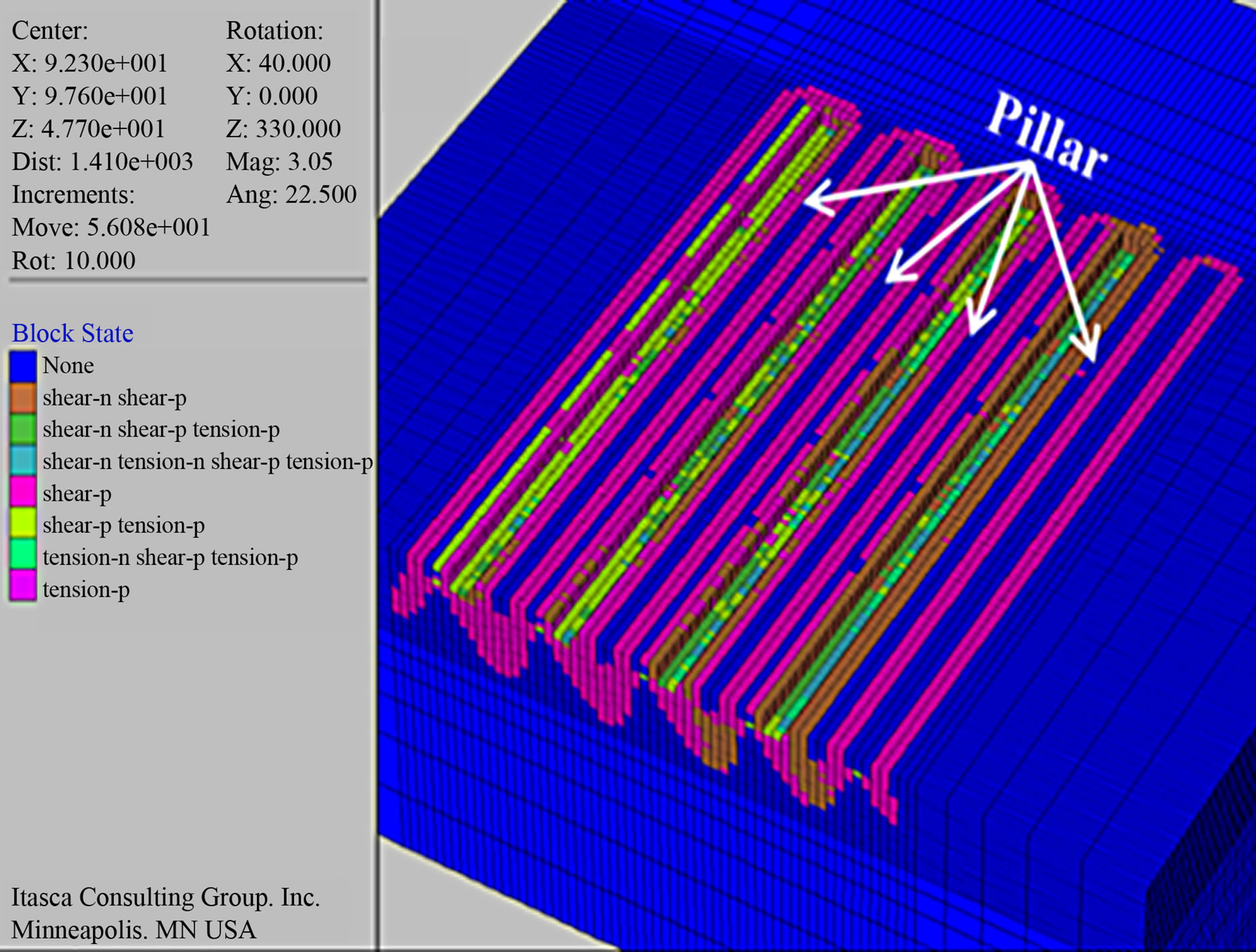 (d)
(d)
Figure 9. Failure states along with the sequences of mining and stowing at the first slice (a) after 1st cut; (b) after stowing the 1st cut; (c) after 2nd cut and (d) after extracting and stowing the whole panel.
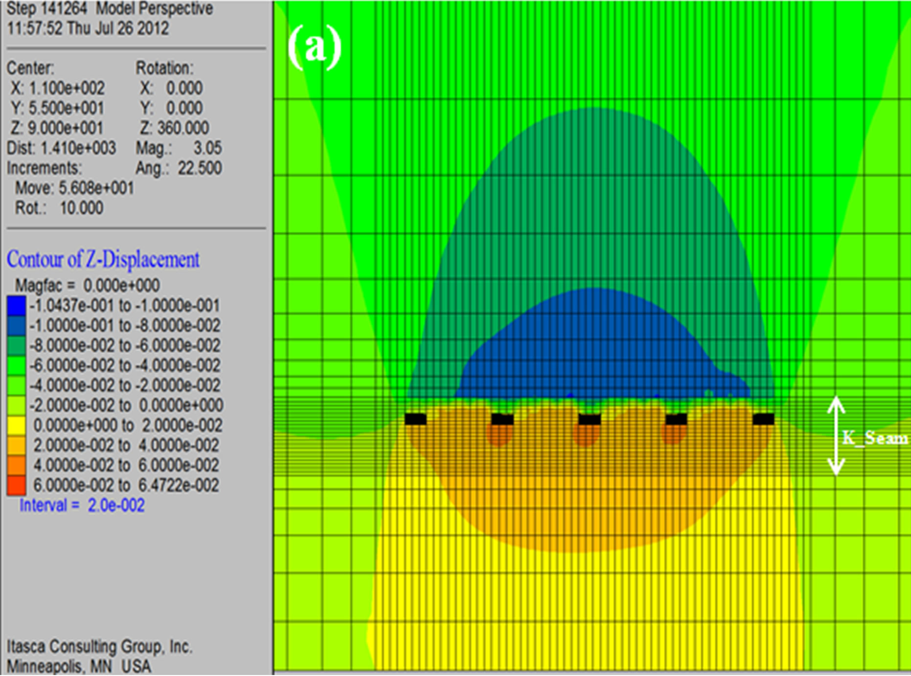

Figure 10. (a) Vertical displacement contours and (b) failure state after 1st cut at the second slice.
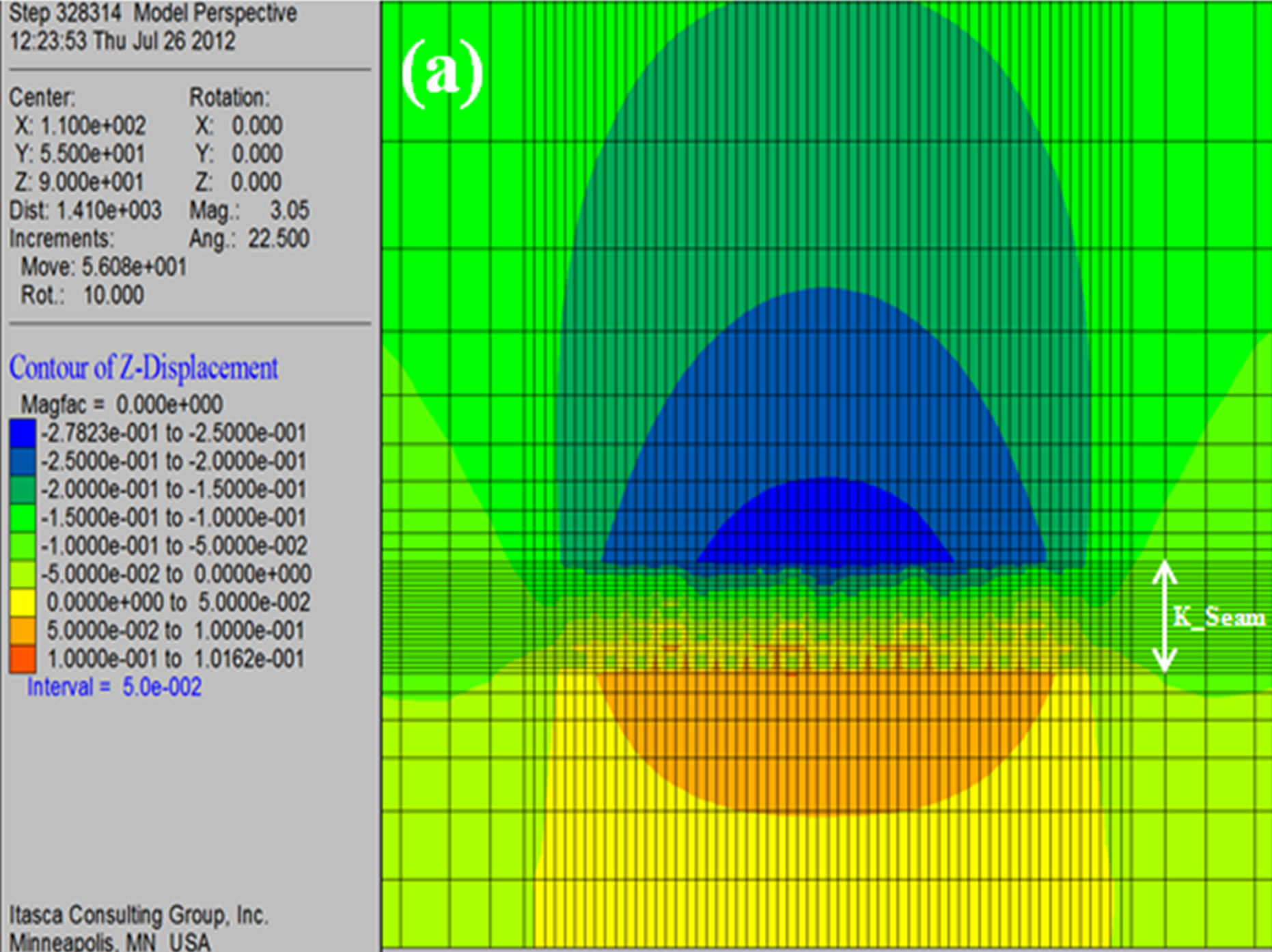

Figure 11. (a) Vertical displacement contours and (b) failure state after extracting the k_seam and stowing in the mine-out voids.
4. Conclusion
According to the results of a series of numerical analysis, it was found that multi-slice bord-and-pillar mining with the alternative method of cutting and stowing discussed in this paper can be employed for the soft extra-thick coal seams and this is an effective method to diminish ground disturbance/environmental impacts, to improve mine safety and to obtain maximum coal recovery. However, it must be evaluated more details for stowing, such as the required strength of stowing material, the method of stowing to be employed as well as the cost and economy of mine, before employing this system.
5. Acknowledgements
The authors wish to express their gratitude to the managers, engineers and miners of EGAT Mae Moh lignite mine for arranging their mine site visit and for providing information. All opinion and comments stated in this paper are those of authors and do not necessarily represent those of the institutions or the mine.
REFERENCES
- R. D. Singh, “Principles and Practices of Modern Coal Mining,” New Age International (P) Ltd., New Delhi, 1997, pp. 249-285.
- M. K. Ozfirat, F. Simsir and A. Gonen, “A Brief Comparison of Longwall Methods Used at Mining of Thick Coal Seams,” Proceedings of the 19th International Mining Congress and Fair of Turkey, Turkey, 9-12 June 2005, pp. 141-144.
- H. Furukawa, K. Matsui and H. Shimada, “The Present Situation and Issues in Coal Mining in India,” Journal of the Mining and Materials Processing Institute of Japan, Vol. 121, No. 9, 2005, pp. 446-455. doi:10.2473/shigentosozai.121.446
- EGAT, “Mae Moh Mine Geotechnical and Slope Stability,” Powerpoint Slides and Reports, 2011.
- P. Doncommul, P. Pimklang, N. Mungpayabal and A. Chaiwan, “Reviews of Slope Failure in Lowwall Area 3 of Mae Moh Mine,” Fuenkajorn and Phienwei, Eds., Rock Mechanics, 2011, pp. 219-227.
- K. Matsui, H. Shimada, T. Sasaoka and H. Furukawa, “Some Consideration in Underground Mining Systems for Extra-Thick Coal Seam,” Coal International, Vol. 259, No. 2, 2011, pp. 38-41.
- M. L. Jeremic, “Strata Mechanics in Coal Mining,” A. A. Balkema Publishers, Leiden, 1985.
- Itasca Consulting Group, Inc., “Flac3D Command Reference,” Mill Place, Minneapolis, 2003, p. 141.
- J. R. Barrett, M. A. Coulthard and R. M. Dight, “Determination of Fill Stability,” Mining with Backfill—12th Canadian Rock Mechanics Symposium, CIM Special Vol. 19, Sudbury, 23-25 May, 1978, pp. 85-91.
- D. R. Tesarik, J. B. Seymour, T. R. Yanske and R. W. Mckibbin, “Stability Analysis of a Backfilled Room-andPillar Mine,” Report of Investigations, United States Bureau of Mines, 1995, pp. 1-26.
- T. Grice, “Underground Mining with Backfill,” The 2nd Annual Summit-Mine Tailings Disposal System, Brisbane, 24-25 November 1998, pp. 1-14.
- K. Matsui, H. Shimada, S. Kramadibrata and M. Zrai, “Some Considerations of Highwall Mining Systems in Coal Mines,” Proceedings of the 17th International Mining Congress and Exhibition of Turkey, Ankara, 19-22 June 2001, pp. 269-276.