Engineering
Vol. 3 No. 9 (2011) , Article ID: 7329 , 5 pages DOI:10.4236/eng.2011.39110
Research on Single-Side Long Edge of Hot Rolled Strip Caused by Asymmetrical Stiffness of Mill Stand
1State Key Laboratory of Rolling Technology and Automation, Northeastern University, Shenyang, China
2School of Mechanical Engineering, Shenyang University of Technology, Shenyang, China
3Electro-mechanical Institute of Technology and Vacation, Panzhihua, China
E-mail: dygong@21cn.com
Received May 11, 2011; revised August 4, 2011; accepted August 15, 2011
Keywords: Hot Rolled Strip Shape, Asymmetric Deformation, Effect Coefficient Method, 4-High Mill
ABSTRACT
To analyze and solve the problem of single-side long edge of hot rolled strip in certain domestic factory, the asymmetrical deformation of rolls and strip in asymmetrical stiffness mill stand based on slit beam model, the strip profile and rolling force distribution at the exit of asymmetric stiffness stand mill were calculated using influence function method. Considering the character of in-site equipment and technology, a scheme of adjusting load distribution in finishing mill was made and the experiment was applied. Comparison of strip profile between new load distribution and the old one shows that the method can solve single-side long edge problem well.
1. Introduction
Strip shape including profile and flatness of hot rolled strip is a difficult problem involving extensive and complex influence factors. There are still many unsolved strip shape problems left for the technicians in site, although long-term exploration and experiment have been made. Flatness problem of thin gauge strip is the most difficult one. As the current theory of shape control is proposed under conditions of axial symmetry or point symmetry [1-4] on one side, on the other side the single-side shape problems are lack of theoretical foundation, especially for thin strip, eventually the quality of strip shape is seriously affected. However the steel shape control mechanism for this can not build based on the theory under symmetry condition. In a certain domestic factory, the single-side long edge problem was serious. In order to solve this problem it is necessary to analyze the impact factors on single-side long edge. Therefore, improving the shape control quality has important theoretical and practical value.
2. Concept of the Single-Side Edge Wave
The unit of strip shape which is called I Unit was proposed by the Alcan Aluminium Co., defined as the relative length difference between the longest and the shortest longitudinal section in horizontal direction. One I unit is equivalent to the relative length difference is 10–5, as given by Equation (1). I unit is currently widely used to measure the shape of strip, as well as the middle section of the strip is normally used to replace the original definition of the shortest fiber longitudinal section, to make it easier to shape representation and measurement.
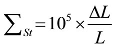 (1)
(1)
where,  is the longitudinal stretch difference, mm.
 ![]() is the length of the shortest section, mm.
is the length of the shortest section, mm.
Strip shape problems present as center wave, edge wave, single-side long edge, side buckle, near-edge buckle, dual buckle and center buckle. When the buckle or wave present in appearance, the internal stress is distributed heterogeneous.
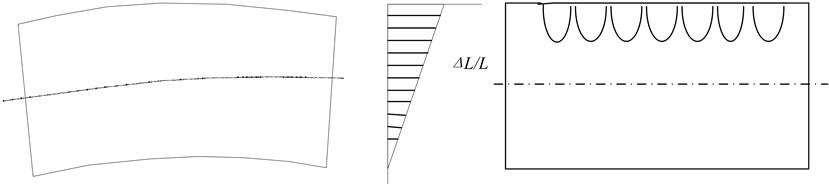
When the uneven distribution of internal stress is sufficient to show the appearance of wave shape, the shape became manifest. When the non-uniform distribution of internal stress does not affect the strip's appearance, a latent wave shape will exist. Long edge wave is a kind of manifest shape existing in the operation or performance of the drive side of the strip as the wave-shaped, while the central and the other side of the strip are straight. The performance of unilateral external waves and the internal stress distribution are shown in Figure 1.
Just as the profile and flatness meter are used for on-line measurement, the concept of steepness is used to express flatness for off-line measurement. The steepness is the ratio of peak-to-peak amplitude and the wave length of a sinusoidal wave, which is given by (2) [5].
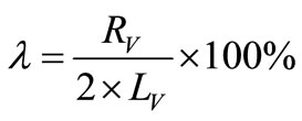 (2)
(2)
where, ![]() is the steepness, %.
is the steepness, %.  is the peak-to-peak amplitude.
  is the wave length.
3. Reasons for Single-side Long Wave
The reason for single-sidelong wave is that the elongation of one side is larger than the center and other side of the strip, the loose side is limited by geometric condition, then the wave is produced. The reasons which produce non-uniform elongation are complex, such as non-uniform temperature of strip across width, the shape problem of slab, strip off-tracking and plant administration. The wedge of slab and asymmetrical stiffness of mill stand sides may cause single-side long wave and hard to be eliminated by management tool.
3.1. Slab Wedge
The strip and slab wedge before rolling mill stands are hard to be measured. The strip thickness distributions across inter-stand strip width were obtained through an experimental test implemented in certain factory, which are presented in Figure 2. As shown in Figure 2, the
 (a) (b) (c)
Figure 1. Example of single-side long edge strip shape. (a) Strip shape (b) fibers elongation distribution (c) observation of single-side long edge shape.
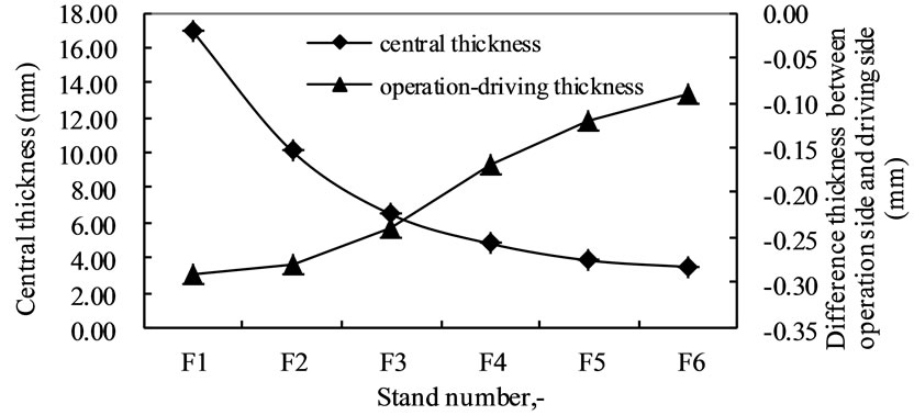
Figure 2. Thickness distribution measured value of hot rolled strip.
difference of thickness between both sides of the strip decrease along with mill stand number increasing from F1 stand to F6 stand, with wedge of slab existing.
3.2. Asymmetric Stiffness of Mill Stand
Single-side long edge is the significant share of strip shape problems, and is hard to be resolved. The strip setup model was bought from a worldwide famous company, the setup strategy is available, and the physical process was described by mathematic model accuracy in detail.
To analyze the reason of single-side long edge, the stiffness of both operation and driving side of mill stand was measured. The data shows that the difference is large enough and should not be eliminated. The difference of mill stand stiffness of both sides can excess 20kN/mm as illustrated in Figure 3.
The stiffness of mill stand can be described as follows: the rolling force increase for unit change of roll gap, which is denoted as the following formula (3).
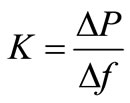 (3)
(3)
where,  is the disturbance of rolling force,
  is the according change of roll gap.
The stiffness of mill stand is a function of rolling force and mill stand spring, if the rolling force and according mill stand spring are measured and logged, the spring curve of stand mill can be obtained by fitting method, the stiffness of mill stand can be derived by using interpolative calculation. The asymmetric character of mill stand stiffness is produced not only by the reasons of mill stand itself, but also the stiffness of roll series. The maximum value of mill stand stiffness difference occurs in different stand during multi-time measurements, this shows that the roll series stiffness difference contributes much to the stiffness asymmetric in this factory. Since the mill stands of this factory were built early, as well as the rolls and roll bearing are not exclusively used for
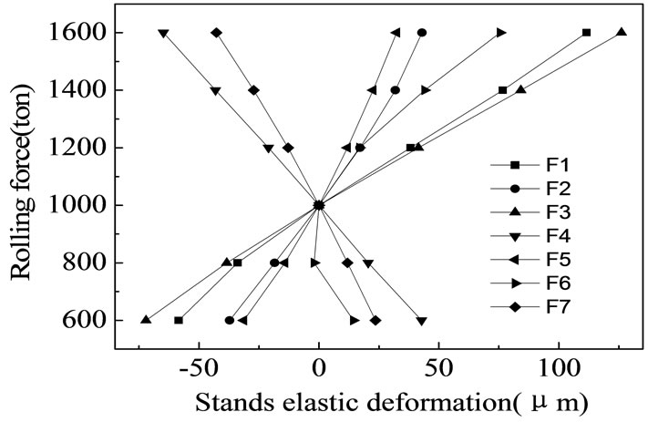
Figure 3. Difference between rigidness of sides of F1-F7 mill.
special mill stand, the asymmetrical stiffness can not be eliminated thoroughly, it is necessary to find a way to overcome it and to avoid the single-side long edge produced by it.
4. Theoretical Calculation
The forces loaded on rolls include rolling force, roll bending force and force between work roll and backup roll. While the mill is symmetric about the middle-span of rolls, the load distribution is illustrated in Figure 4 [6,7]. As shown in Figure 4, the F is work roll bending force, the  is the force between work roll and backup roll, the
  is the rolling force. When the symmetrical condition is broken by asymmetrical stiffness, temperature distribution or slab wedge, the symmetrical as shown in Figure 4 will not exist anymore.
To analyze lateral distribution of the load distribution and thickness, the effect function method was adopted to construct the model of roll elastic deformation. The effect function method can be denoted as follows: the concept of influence function was induced from the Mathematic Physics, the influence function of work roll deflection effect rate and backup roll effect rate were derived based on the influence function theory. The rolls, load and lateral deformation of roll were scattered with the same elements arrangement away axial direction of work roll. Firstly, the deformation of elements produced by according load was calculated, then, all the deformation of elements was added with the whole load applied, therefore, the deformation of all the elements was calculated. As a result, the distribution of strip thickness in lateral direction can be obtained.
The method of elements’ numbers layout of workpiece and roll are denoted as Figure 5. For the first method, the elements are arranged from middle span to both sides, totally N3 numbers, the method is for the research of “dog bone”. The second method is to arrange the elements from left to right along with the backup roll barrel. N1 is the number of roll contact part, is used to research the roll pressure between work roll and backup roll, and the slit beam deflection. The discretization of
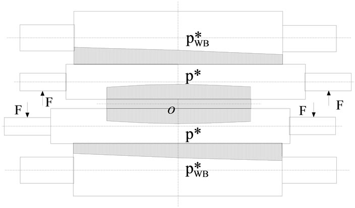
Figure 4. Force distribution diagram of 4-high mill.
rolling force, roll pressure, the deflection of work roll and backup roll, and the strip thickness lateral distribution are scattered by the numbers distribution.
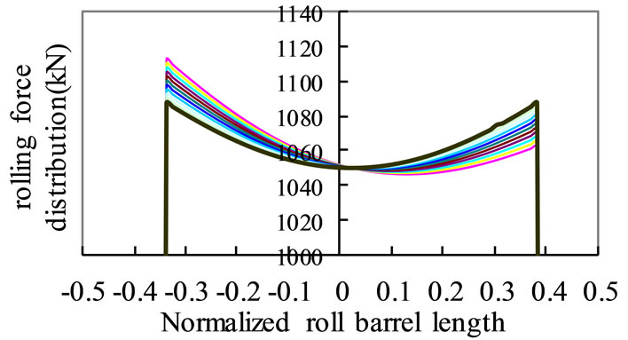
To analyze the deformation of rolls, distribution of force and rolled strip profile, a calculation was made by using a software coded for asymmetrical deformation of roll series [8-10]. The calculation was based on engineering log data gathered in site, due to the F3 mill stand, which has serious asymmetrical stiffness characteristic. For the calculation, supposing that the stiffness of driving side of mill stand is 620 t/mm and the stiffness of operation side is 600 t/mm ~ 620 t/mm (2 t/mm as step length), the rolling force distribution in lateral direction was obtained as shown in Figure 6(a), the strip lateral thickness distribution was illustrated in Figure 6(b).
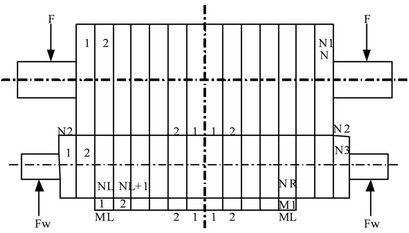
Figure 5. Elements split of roll and strip.
 (a)
(a)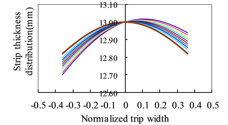 (b)
(b)
Figure 6. (a) Rolling force distribution when stiffness is asymmetric on stand sides. (b) Strip thickness distribution when stiffness is asymmetric on stand sides.
As shown in Figure 6(a), when the stiffness of mill stand is asymmetrical, the unit width rolling force is larger at the bigger stiffness side. From the end of bigger stiffness, the unit rolling force decreases as parabola, the minimum value of the unit rolling force is located at the point with a distance of 0.15 times of half strip width away from the strip center line. After the minimum value location, the unit rolling force increases. The difference of unit rolling force can reach 50 kN.
Figure 6(b) presents the rolled strip thickness distribution along lateral direction. The strip thickness distribution is inversely with the unit width rolling force, the strip thickness difference can reach 240 µm under the calculation condition.
5. Experimental Test in Site
Since the stiffness of mill stand is a function of rolling force and roll gap as denoted in the formula (3), the difference of stiffness of driving side and operation side of mill stand is a function of rolling force too. According to the measurement data, F3 and F5 stand have the largest difference of stand stiffness as illustrated in Figure 3. Stand stiffness increases with the increasing of rolling force. When the total rolling force is more than 13000 kN, stiffness difference becomes obviously, if the total rolling force is less than 13,000 kN, the stiffness difference is little enough. The total rolling force of F5 stand is always less than 10,000 kN, the total rolling force of F3 stand is more or less than 13,000 kN due to the product thickness. It is definitely needed to change something in F3 stand, while the rolling force and stiffness difference is not constant. It is not effective to change roll gap profile through rolls tilting, but changing the rolling force of F3 should be useful.
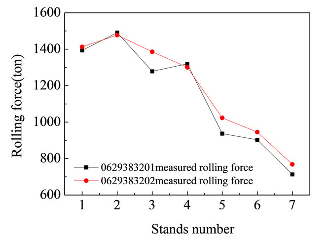
Two coils of steel were chosen, the steel grade is BG380CL, the coil ID are 0629383201 (first steel) and 0629383202 (second steel) respectively. For the first steel, the rolling force of F3 stand was decreased to 96.7 percent of it should be (from 13127 kN to 12690 kN).
The rolling forces of the two rolled strip are presented in Figure 7(a), and the strip lateral thickness distribution of the two rolled strip are given by Figure 7(b). The target thickness of the first steel and second steel is 5.75 mm. For the whole strip, the hit rate of target thickness of the first steel is 96.96 percent (with a tolerance of ±0.05 mm). The hit rate of the second steel is 99.17 percent. This shows that the change of rolling force of F3 stand will not change the exit thickness of finishing mill.
The target crown is 92 µm for the two steels. For the first steel, the hit rate of target crown is 68.31 percent (with a tolerance of 15 µm), after changing the rolling force of F3 stand, the hit rate of target is 83.33 percent.
 (a)
(a)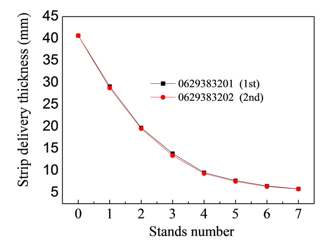 (b)
(b)
Figure 7. (a) Measured rolling force of the 1st and 2nd coil. (b)Thickness of the 1st and 2nd coil.
For the first steel, there was some insignificant single-side long edge, but after changing rolling force of F3 stand, no flatness defect was observed.
6. Conclusions
1) The asymmetrical stiffness between operation side and driving side of mill stand can produce rolling force and thickness inhomogeneous alone with lateral direction of strip. At the side with larger stiffness, the rolling force is larger, the strip is thinner, vice versa.
2) Using the method of decreasing rolling force of the special mill stand with asymmetrical stiffness to eliminate the effect of asymmetrical stiffness can obtain better profile curve as well as good flatness.
7. Acknowledgements
This paper is supported by Scientific Research Foundation for Young Teachers ( N100307001).
8. REFERENCES
- P. M. Lugt and W. E. Tennapel, “The Influence of Elastic-Deformation of the Roll and the Sheet in a Hydrodynamically Lubricated Cold-Rolling Process,” Journal of Tribology-Transactions of the Asme, Vol. 117, No. 3, 1995, pp. 468-475.
- D. X. Luo, Q. A. Chen and L. W. Liu, “Finite Element Analysis for Effect of Roll Radius on Metal Deformation of Hot Rolling Plate,” Journal of Iron and Steel Research International, Vol. 12, No. 1, 2005, pp. 17-21.
- V. Salganik, “Mathematical Modelling of Roll Load and Deformation in a Four-High Strip Mill,” Journal of Materials Processing Technology, Vol. 125, 2002, pp. 695- 699. doi:10.1016/S0924-0136(02)00355-2
- J. N. Sun, F. S. Du and X. T. Li, “FEM Simulation of the Roll Deformation of Six-high CVC Mill in Cold Strip Rolling,” Proceedings of 2008 International Workshop on Modelling, Simulation and Optimization, 27-28 December 2009, pp. 412-415.
- V. B. Ginzburg, “High-Quality Steel Rolling: Theory and Practice,” Marcel Dekker, Inc. New York, 1993, pp. 26-27.
- K. N. Shohet and N. A. Townsend, “Roll Bending Methods of Crown Control in Four-High Plate Mills,” Journal of Iron and Steel Institute, No. 11, 1969, pp. 11088-1098.
- G. D. Wang, “Shape Control and Shape Theory,” Metallurgical Industry Press, Beijing, 1986, p. 11.
- J. Xu, F. Zhang, D. Gong, et al., “Development of Calculation Module about Rolls Elasticity Deformation in 4 High Mill,” in Chinese, Steel Rolling, Vol. 20, No. 2, 2003, pp. 8-11.
- J. Xu, D. Gong, D, W. Zhang, et al., “Model Building of the Initial Crown Effect Rate in 4-High Mill,” Journal of Materials Science and Technology, Vol. 21, No. 2, 2005, pp. 165-169.
- D. Gong, J. Xu, Z. Jiang, et al., “Setup Models of Finishing Temperature and Rolling Speed for Hot Strip Mill,” Steel Research International, Vol. 81, No. 9, 2010, pp. 62-65.