Intelligent Control and Automation
Vol. 3 No. 3 (2012) , Article ID: 22048 , 7 pages DOI:10.4236/ica.2012.33027
A Novel 4WD Electric Vehicle Control Strategy Based on Direct Torque Control Space Vector Modulation Technique
Faculty of the Sciences and Technology, Bechar University, Bechar, Algeria
Email: gasbaoui_2009@yahoo.com
Received February 26, 2012; revised June 15, 2012; accepted June 23, 2012
Keywords: 4WD; SVM-DTC; Control; Electric Vehicle; SOC
ABSTRACT
Four-Wheels-Drive (4WD) Electric Vehicle (EV) controlled with Direct Torque Control based Space Vector Modulation (DTC-SVM) is presented, where the electrical traction chain was well analyzed and studied from the lithium battery, the buck boost to the mechanical load behavior. The speed of four wheels is calculated independently during the turning with the electronic differential system computations which distributes torque and power to each in-wheel motor according to the requirements, adapts the speed of each motor to the driving conditions. The basic idea of this work is to maintain the initial battery state of charge (SOC) equal to 70% and the prototype was tested in several topology conditions and under speed. The simulations carried in Matlab/Simulink verified the efficiency of the proposed DTC-SVM controller, and show that the system has more favorable dynamic performance. Results also indicate that this strategy can be successfully implemented into the traction drive of the modern 4WD electric vehicles.
1. Introduction
The principal constraints in vehicle design for transportation are the development of a non-polluting high safety and comfortable vehicle. Taking into account these constraints, our interest has been focused on the 4WD Electrical Vehicle, with independent driving wheel-motor at the front and with classical motors on the rear drive shaft [1-5]. This configuration is a conceivable solution, the pollution of this vehicle is strongly decreased and electric traction gives the possibility to achieve accurate and quick control of the distribution torque. Torque control can be ensured by the inverter, so this vehicle does not require a mechanical differential gear or gearbox. One of the main issues in the design of this vehicle (without mechanical differential) is to assume the car stability. During normal driving condition, all drive wheel system requires a symmetrical distribution of torque in the both sides. In recent years, due to problems like the energy crisis and environmental pollution, the Electric Vehicle (EV) has been researched and developed more and more extensively [1,2]. Currently, most EVs are driven by two front wheels or two rear wheels. Considering some efficiency and space restrictions on the vehicle, people have paid more and more attention in recent years to fourwheel drive vehicles employing the IM in-wheel motor.
The Direct Torque Control strategy (DTC) is one kind of high performance driving technologies for AC motors, due to its simple structure and ability to achieve fast response of flux and torque has attracted growing interest in the recent years. DTC-SVM with PI controller direct torque control without hysteresis band can effectively reduce the torque and flux ripple, DTC-SVM method can improve the system robustness and effectively improve the system dynamical performance. The DC-DC converter is used with wide range in electric vehicles to assure the energy require for the propulsion system.
The aim of this paper is to understand the lithium-ion battery comportment controlled by DC-DC converter, each wheels is controlled independently by using direct torque control based space vector modulation under several topology and speed variation.
Modeling and simulation are approved out using the Matlab/Simulink tool to study the performance of 4WD proposed system.
2. Electric Vehicle Description
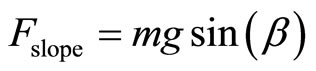
According to Figure 1 the opposition forces acting to the vehicle motion are: the rolling resistance force Ftire due to the friction of the vehicle tires on the road; the aerodynamic drag force Faero caused by the friction on the body moving through the air; and the climbing force Fslope that depends on the road slope [1-3].
The total resistive force is equal to Fr and is the sum of the resistance forces, as in (1).
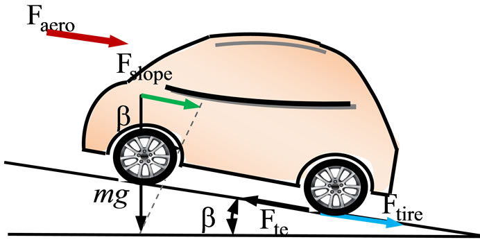
Figure 1. The forces acting on a vehicle moving along a slope.
Fr = Ftire + Faero + Fslope (1)
The rolling resistance force is defined by:
Ftire = mgfr(2)
The aerodynamic resistance torque is defined as follows:
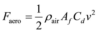 (3)
(3)
The rolling resistance force is usually modeled as:
 (4)
(4)
where r is the tire radius, m is the vehicle total mass, fr is the rolling resistance force constant, g the gravity acceleration,  is air density, Cd is the aerodynamic drag coefficient, Af is the frontal surface area of the vehicle, v is the vehicle speed,
  is the road slope angle. Values for these parameters are shown in Table 1.
3. Direct Torque Control Strategy Based Space Vector Modulation (SVM-DTC)
In this technique two proportional integral (PI) type controllers are used instead of hysteresis band regulating the torque and the magnitude of flux as it shown in Figure 2, by generating the voltage command for inverter control. Noting that no decoupling mechanism is required as the flux magnitude and the torque can be regulated easily by the PI controllers. Due to the structure of the inverter, the DC bus voltage is fixed, therefore the speed of voltage space vectors are not controllable, but we can adjust the speed by means of inserting the zero voltage vectors to control the electromagnetic torque generated by the induction motor. The selection of vectors is also changed. It is not based on the region of the flux linkage, but on the error vector between the expected and the estimated flux linkage [6].
The induction motor stator flux can be estimated by:
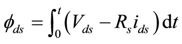 (5)
(5)
 (6)
(6)
 (7)
(7)
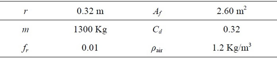
Table 1. Parameters of the electric vehicle model.
 (8)
(8)
The electromagnetic torque Tem can be given as follow:
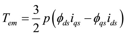 (9)
(9)
The SVM principle is based on the switching between two adjacent active vectors and two zero vectors during one switching period. It uses the space vector concept to compute the duty cycle of the switches.
4. Simulation Results
In order to analyze the driving wheel system behavior, simulations were carried using the model of Figure 3. The following results were simulated in MATLAB and its divided in two phases. The first one deal with the test of the EV performances controlled with DTC-SVM strategy under several topology variation in the other hand we show the impact of this controller on vehicle power electronics performances. Only the right motor simulations are shown. The assumption that the initialized lithiumion battery SOC is equal to 70% during trajectories.
4.1. Direct Torque Control Scheme with Space Vector Modulation
The topology studied in this present work consists of four phases: the first one is the beginning phase’s with speed of 80 Km/h in straight road topology, the second phase present the curved road with the same speed, in the third phase the 4WD moving up the sloped road of 10% under 80 Km/h, finally the deceleration phases, the specified road topology is shown in Figure 4, when the speed road constraints are described in the Table 2.
Refereed to Figure 5 at time of 2 s the vehicle driver turns the steering wheel on a curved road at the right side with speed of 80 Km/h, the assumption is that the four motors are not disturbed. In this case the front and rear driving wheels follow different paths, and they turn in the same direction but with different speeds. The electronic differential acts on the four motor speeds by decreasing the speed of the driving wheel on the right side situated inside the curve, and on the other hand by increasing the wheel motor speed in the external side of the curve. The behaviors of these speeds are given in Figure 5. At t = 3 s the vehicle situated in the second curve but in the left side, the electronic differential compute the
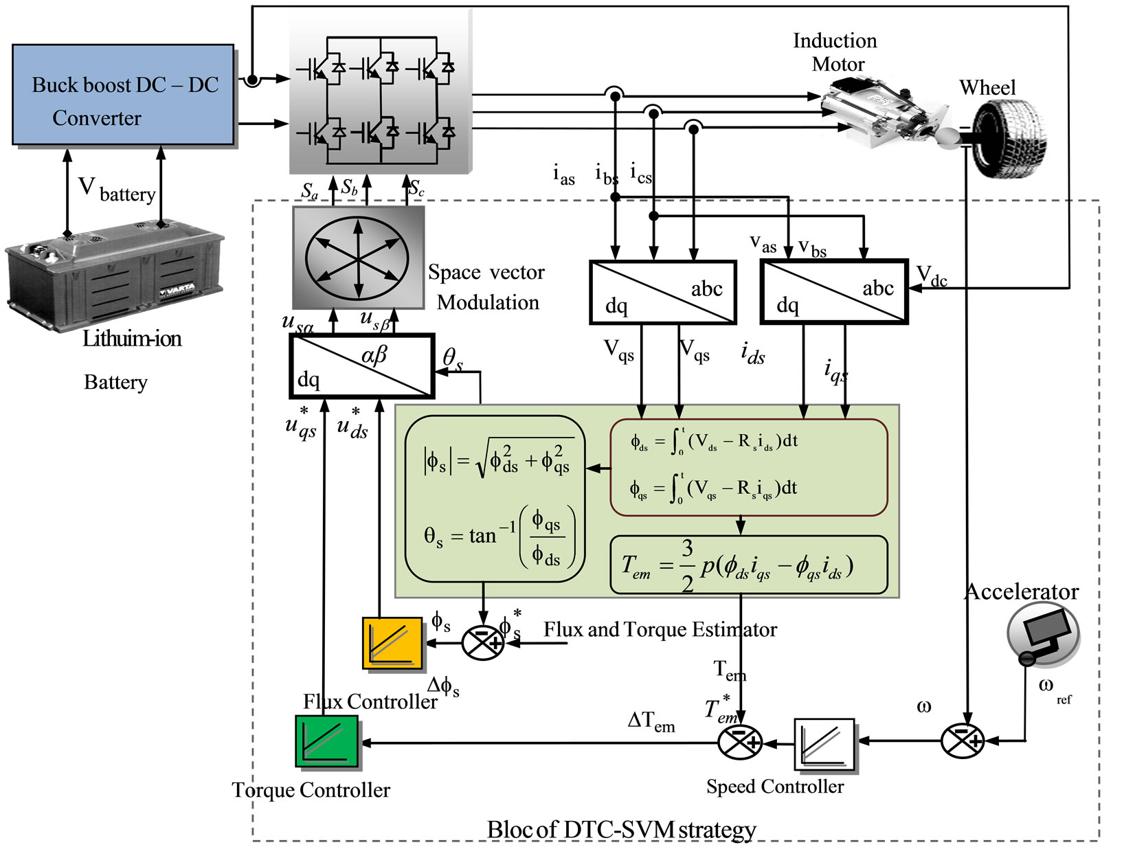
Figure 2. Bloc diagram for DTC strategy based space vector modulation.
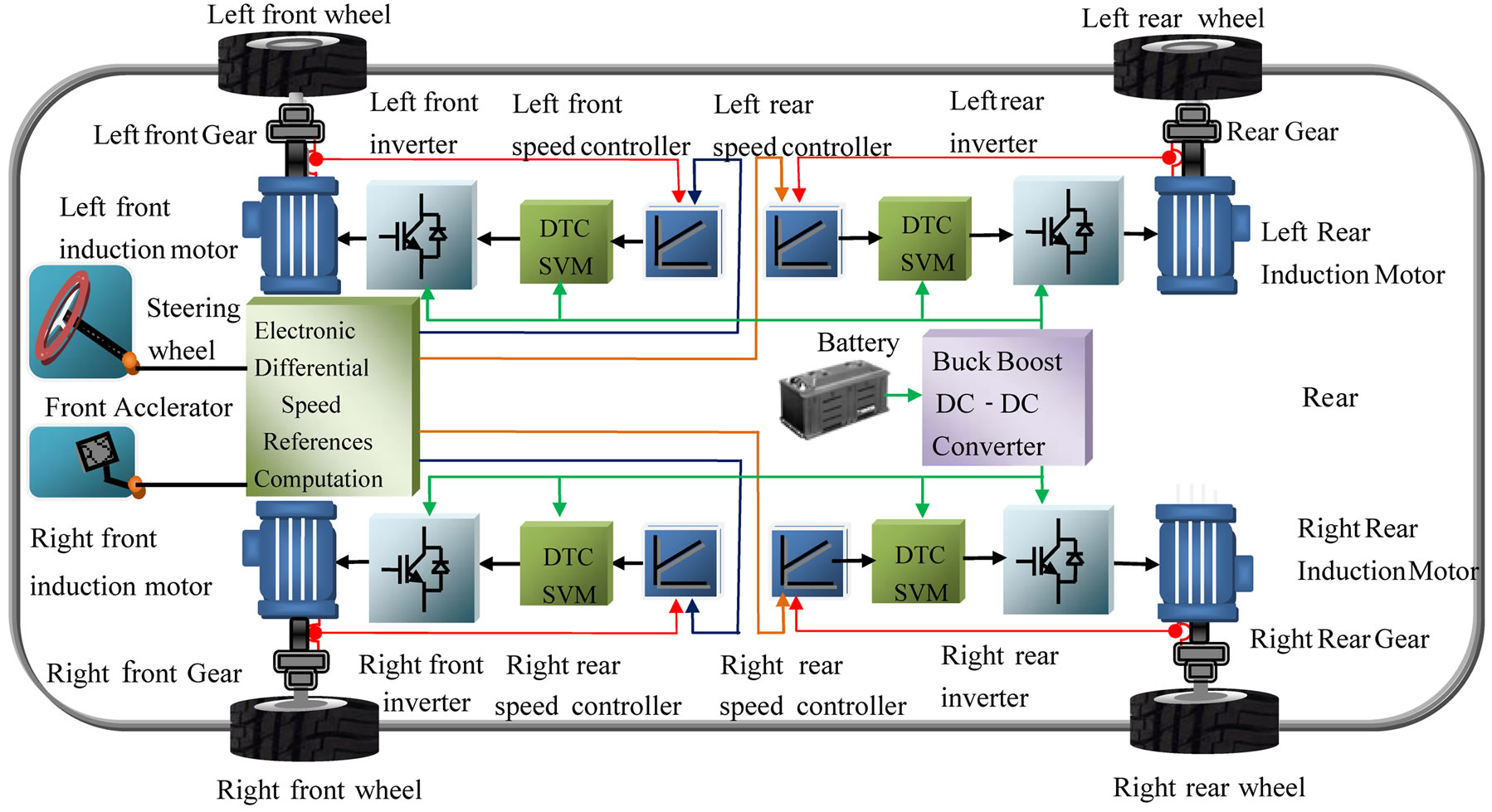
Figure 3. The driving wheels control system.
novel steering wheels speeds references in order to stabilize the vehicle inside the curve. The battery initial SOC of 70% is respected. In this case the driving wheels follow the same path with no overshoot and without error which can be justified with the good electronic differential act coupled with DTC-SVM performances.
Figure 6 reflects the relationship between vehicle speed’s variation and distance traveled in different phases. The distance traveled is 406.50 m in four trajectory phases.
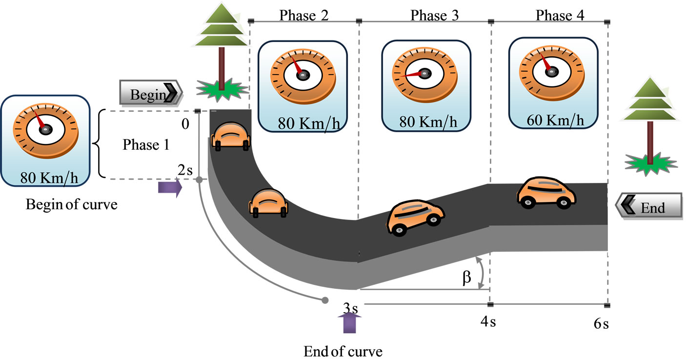
Figure 4. The chosen road topology of tests.
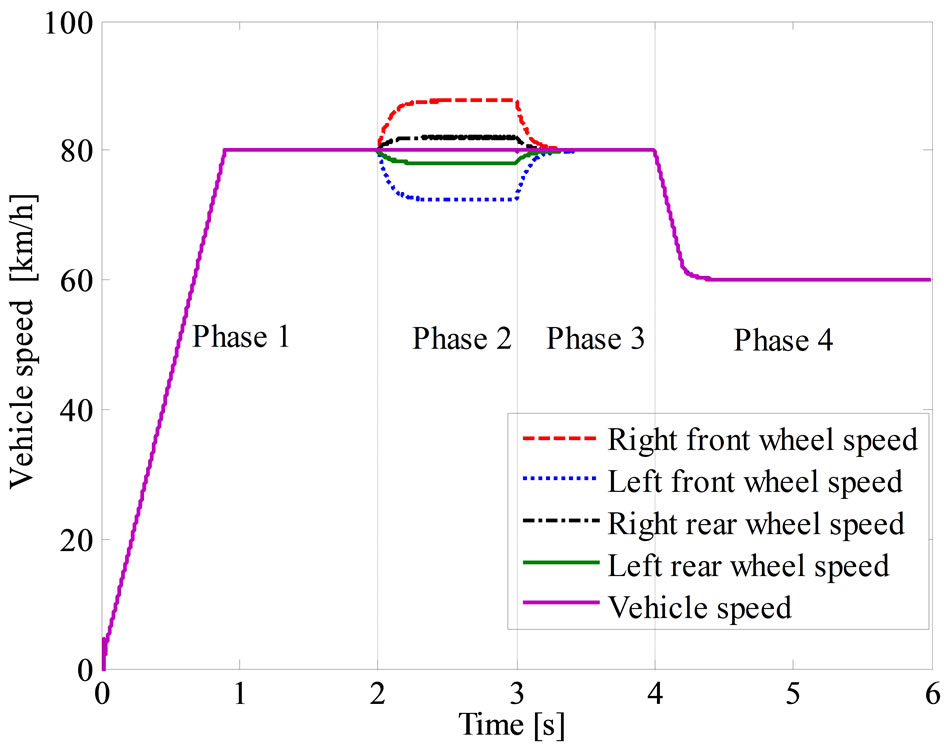
Figure 5. Variation of vehicle speeds in different phases.
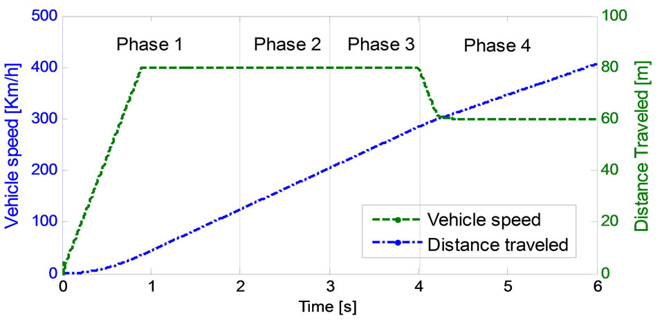
Figure 6. Evaluation of vehicle and distance traveled in different phases.
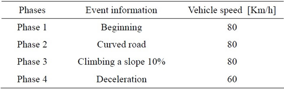
Table 2. The driving road topology description.
Figures 7-10 and Table 3, explain the variation of phase current and electromagnetic torque respectively. In the first step and to reach 80 Km/h. The EV demands a current of 21.10 A for each motors which explained with electromagnetic torque of 42.96 N.m. In the curved road the current and electromagnetic torque demand are computed using the electronic differential process according to the driver decision by means that the speed reference of each wheel is given by the electronic differential computations witch convert the braking angle in the curve on linear speeds. The Figures 7 and 8 show the electromagnetic torque of the front right and rear right motor respectively. The third phase explains the effect of the sloped road the electromagnetic torque increase and the current demand undergo double of the current braking phases. The four motor induction develops more and more electromagnetic torque for vanquish the slop. They develops approximately 53.28 N.m each one. The linear speeds of the four induction motors stay the same and the road drop does not influence the torque control of each wheels. The last phases illustrate the deceleration effect. The results are listed in Table 3.
According to the formulas (1), (2), (3) and (4) and Table 4, the variation of vehicle torques in different cases as depicted in Figure 11, the vehicle resistive torque was 127.60 N.m in the first case (beginning phase) when the power propulsion system resistive one is 127.60 N.m in the curved road. The driving wheels develop more and more efforts to satisfy the traction chain demand which justify a resistive torque equal to 168.00 N.m in the third slopped phase. The result prove that the traction chain under acceleration demand develop the double effort comparing with the breaking phase case’s by means that the vehicle needs the half of its energy in the deceleration phase’s compared with the acceleration one’s as it specified in Table 4 and Figure 11.
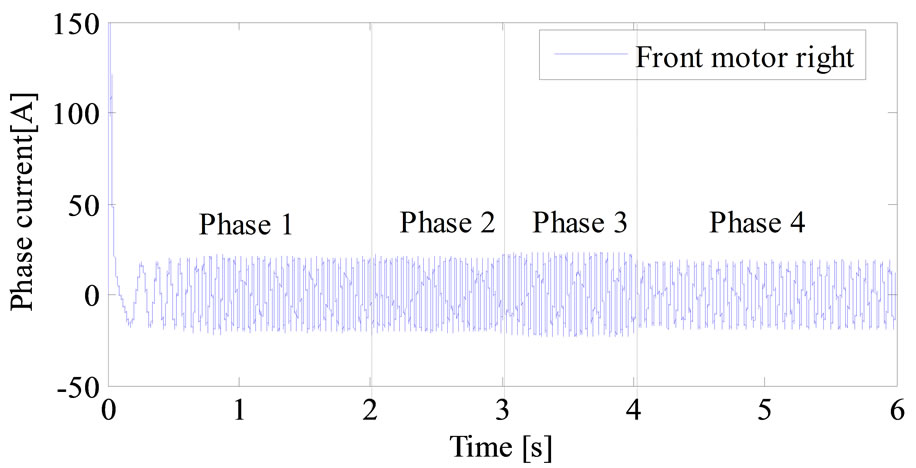
Figure 7. Variation of phase current of the rear right motor in different phases.
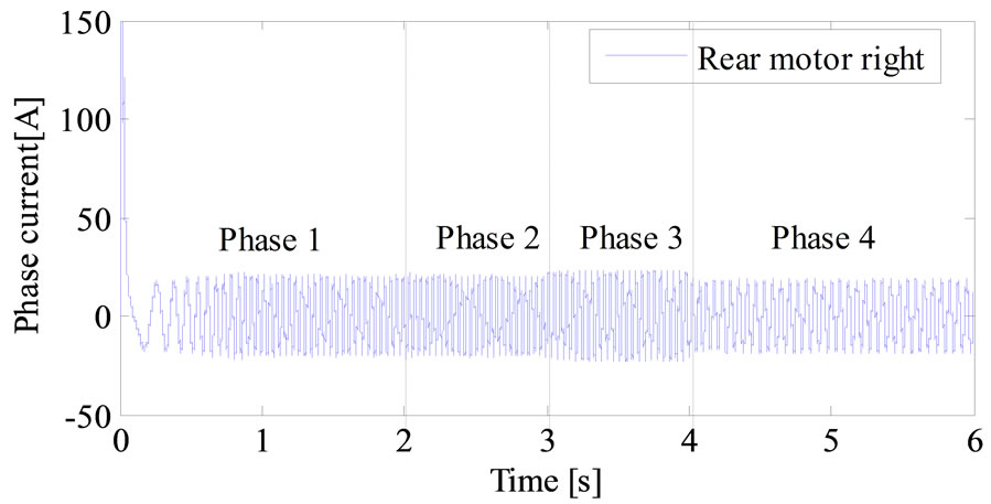
Figure 8. Variation of phase current of the front motor right in different phases.
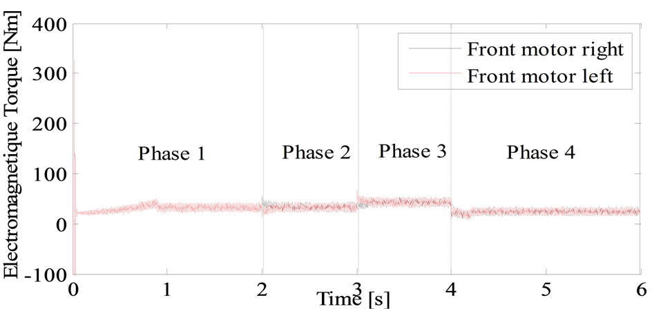
Figure 9. Variation of electromagnetic torque of the front motor right in different phases.
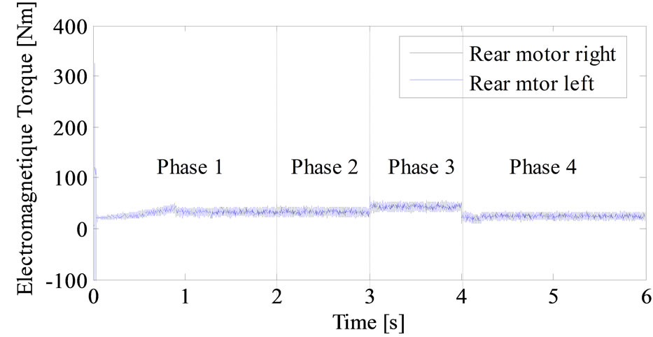
Figure 10. Variation of electromagnetic torque of the rear motor right in different phases.
4.2. Power Electronics
The Lithium-ion battery must be able to supply sufficient power to the EV in accelerating and decelerating phase, which means that the peak power of the batteries supply
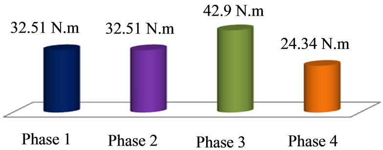
Figure 11. Evaluation of the globally vehicle resistive torque compared to nominal motor torque in different phases.

Table 3. Values of phase current driving force of the right motor in different phases.
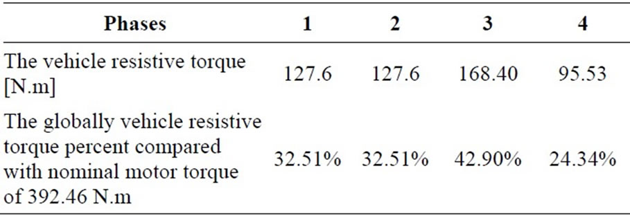
Table 4. Variation of vehicle torque in different phases.
must be greater than or at least equal to the peak power of the both electric motors. The battery must store sufficient energy to maintain their SOC at a reasonable level during driving, the Figure 12, describes the changes in the battery storage power in different speed references in this way, the Table 5 describes the variation of power electronics in the different trajectory paths.
It is interesting to describe the power distribution in the electrical traction under several speed references as it described in Figures 12-14. The battery provides about 9.86 Kw in the first phase in order to reach the electronic differential reference speed of 80 Km/h. In the second phase (phase 2: curved phase’s) the demanded power battery stay the same which present amount of 32.19% of the globally nominal power battery (31 Kw). In third phase the battery produced power equal to 12.98 Kw under slopped road state. The battery produced power depend only on the electronic differential consign by means the acceleration/deceleration driver state which can be explained by the battery SOC of Figure 15.
Figure 15 explains how SOC in the Lithium-ion battery changes during the driving cycle; it seems that the SOC decreases rapidly at acceleration, by means that the SOC range’s between 67.93% to 70% during all cycle’s phases from beginning at the end cycles.
At t = 6 s, the battery SOC becomes lower than 68.93% (it was initialized to 70% at the beginning of the simulation).
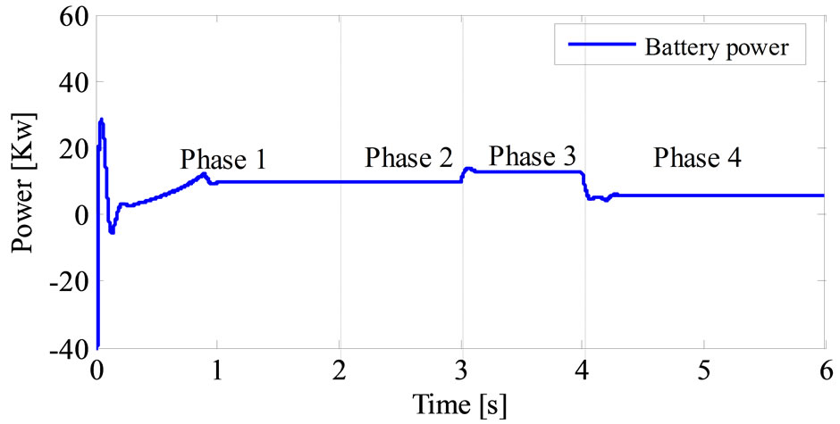
Figure 12. Variation of Lithium-ion battery power in different phases.
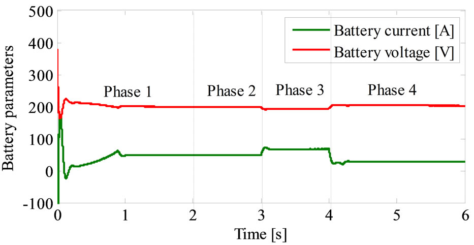
Figure 13. Variation of battery current and voltage during trajectory.
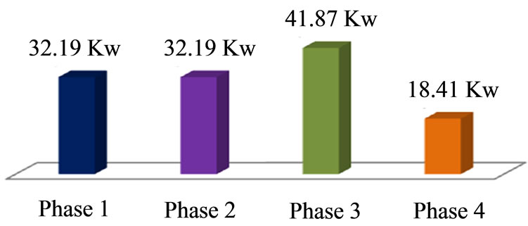
Figure 14. Variation of the maximum power battery in different phases in [%].
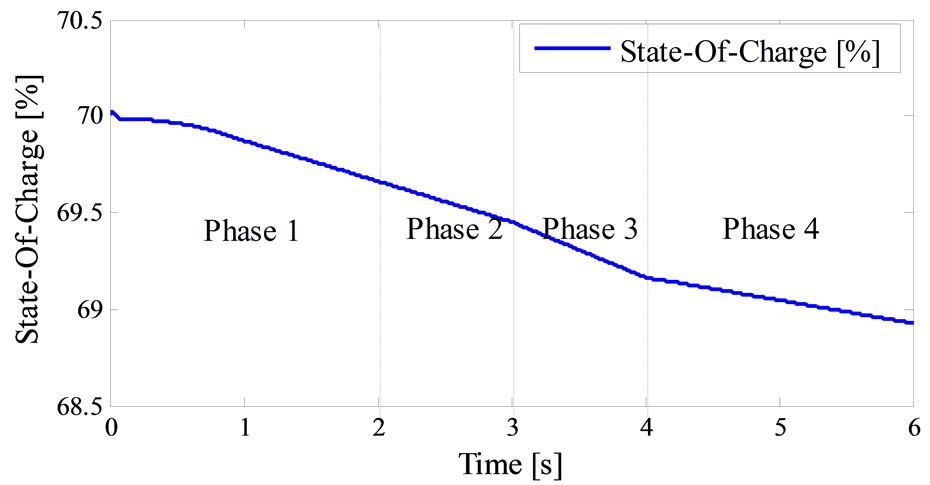
Figure 15. Battery efficiency versus state-of-charge.
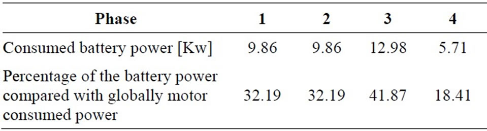
Table 5. Variation of battery power in different trajectory phases.
Table 6 reflects the variation of SOC in different simulations phases.
Figure 16 investigates the variation of sate of charge function of vehicle speed and the traveled distance respectively. The relationship between SOC and left time in four phases are defined by the flowing linear fitting formula:
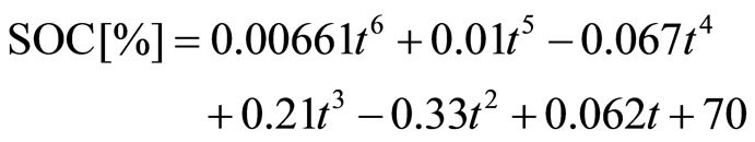 (10)
(10)
Moreover the simulation results specified by Figure 16, we can define the relationship between the sate of charge and the traveled distance in each cases as it’s detailed in Table 7, and the relationship between power consumed and the distance traveled is given in Table 8, the first one (beginning phase) is defined by the linear fitting formula:
Figure 17. Evaluation of the SOC during traveled distance.
 (11)
(11)
The second (curved road) is obtained and represented by:
 (12)
(12)
The third (sloped road) is obtained by:
 (13)
(13)
Finally the ford phase’s formula (deceleration) is given by:
 (14)
(14)
This power is controlled by the Buck Boost DC-DC converter current and distribute accurately for four phases. Figure 17 shows the buck boost DC-DC converter robustness under several speed cycles. The buck boost converter is not only a robust converter which ensures the power voltage transmission but also a good battery recharger in deceleration state that help to perfect the vehicle autonomous with no voltage ripple.
5. Conclusion
The research outlined in this paper presents a novel assisted steering system and global torque distribution con-
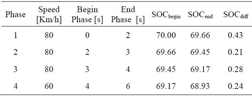
Table 6. Evaluation of SOC [%] in the different phases.
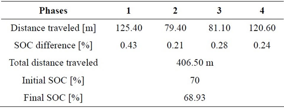
Table 7. Evaluation of distance traveled and SOC.
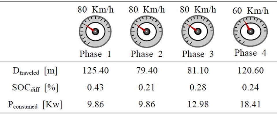
Table 8. The relationship between the traction chain power electronics characteristics and the distance traveled in different phases.
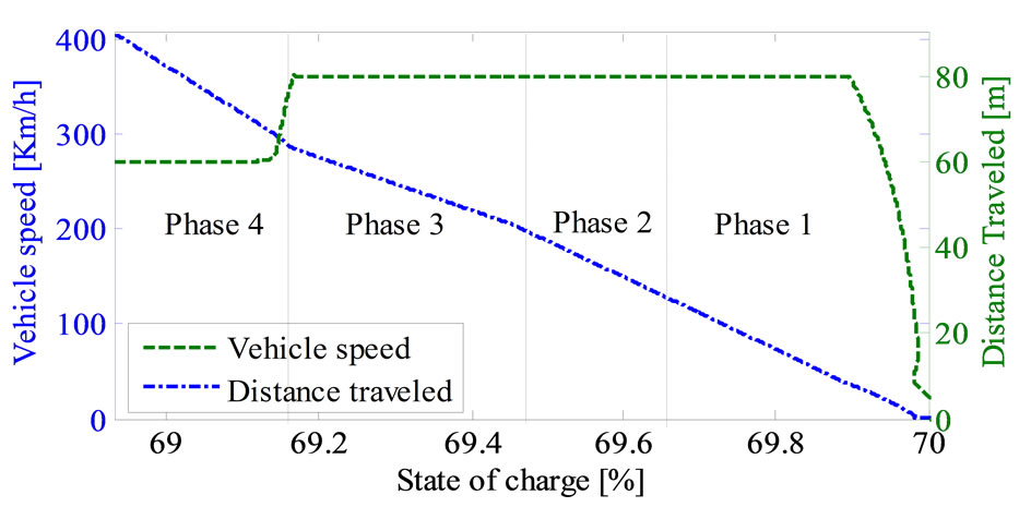
Figure 16. Variations of the SOC during traveled distance in versus vehicle speed.
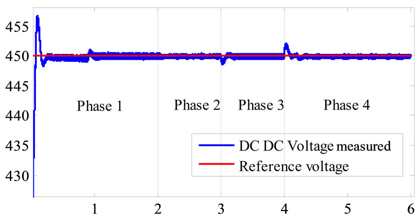
Figure 17. Buck boost DC-DC converter behavior under several speed variations.
trol system for four-wheel-independent-drive electric vehicle. The system is based on applying a differential torque between the right and left front wheels to minimize the difference between the actual steering torque and the reference steering torque, which is mapped by the vehicle speed and steering wheel position. The simulation results prove that the direct torque control based space vector modulations improve the driving wheels speeds control with high accuracy in curved road or in slopped ones. The road topology disturbances, the driver decisions do not affect the performances of the driving motors in the other hand the proposed control gives good dynamic characteristics of the traction chain. It can be concluded that this novel power control DTC-SVM strategy, which is based on the characteristics of independent drive of electric vehicle, may be applied to four-wheelindependent-drive EV in the future.
REFERENCES
- J. Wang, Q. Wang, L. Jin and C. Song, “Independent Wheel Torque Control of 4WD Electric Vehicle for Differential Drive Assisted Steering,” Mechatronics, Vol. 21, 2011, pp. 63-76. doi:10.1016/j.mechatronics.2010.08.005
- J. Wang, Q. Wang and L. Jin, “Modeling and Simulation Studies on Differential Drive Assisted Steering for EV with Four-Wheel-Independent-Drive,” Proceedings of the 4th IEEE Vehicle Power and Propulsion Conference (VPPC2008), Harbin, 3-5 September 2008, pp. 1-7.
- H. Yoichi, T. Yasushi and T. Yoshimasa, “Traction Control of Electric Vehicle: Basic Experimental Results Using the Test EV ‘UOT Electric March’,” IEEE Transaction on Industry Application, Vol. 34, No. 5, 1998, pp. 1131-1138.
- F. Wu and T. J. Yeh, “A Control Strategy for an Electrical Vehicle Using Two In-Wheel Motors and Steering Mechanism,” Proceedings of AVEC’08, Kobe, 6-9 October 2008, pp. 796-801.
- S. Shin-Ichiro, S. Hideo and H. Yoichi, “Motion Control in an Electric Vehicle with Four Independently Driven In-Wheel Motors,” IEEE Transactions on Mechatronics, Vol. 4, No. 1, 1999, pp. 9-16. doi:10.1109/3516.752079
- T. G. Habetler, F. Profumo, M. Pastorelli and L. Tolbert, “Direct Torque Control of Induction Machines Using Space Vector Modulation,” IEEE Transaction on Industry Applications, Vol. 28, No. 5, 1992, pp. 1045-1053. doi:10.1109/28.158828