Materials Sciences and Applications
Vol.09 No.04(2018), Article ID:83849,19 pages
10.4236/msa.2018.94027
Very High Cycle Fatigue Behaviors and Surface Crack Growth Mechanism of Hydrogen-Embrittled AISI 304 Stainless Steels
Seung-Hoon Nahm1, Hyun-Bo Shim2, Un-Bong Baek1, Chang-Min Suh3*
1Korea Research Institute of Standards and Science, Daejeon, Republic of Korea
2School of Mechanical Engineering, Yeungnam University, Daegu, Republic of Korea
3School of Mechanical Engineering, Kyungpook Nat’l University, Daegu, Republic of Korea

Copyright © 2018 by authors and Scientific Research Publishing Inc.
This work is licensed under the Creative Commons Attribution International License (CC BY 4.0).
http://creativecommons.org/licenses/by/4.0/


Received: January 29, 2018; Accepted: April 16, 2018; Published: April 19, 2018
ABSTRACT
The influence of hydrogen embrittlement on the fatigue behaviors of AISI 304 stainless steel is investigated. The fatigue endurance limits of the untreated and hydrogen-embrittled materials were almost the same at 400 MPa, and hydrogen embrittlement had little influence even though the sample contained about 8.1 times more hydrogen. Thus, the sensitivity of hydrogen gas in this material is very low. A surface crack initiation, growth, coalescence, and micro ridge model is proposed in this study. Slip line formation ⇒ microcrack formation ⇒ increases in the crack width, and blunting of the crack tip as it grows ⇒ formation of many slip lines because of deformation in the shear direction ⇒ growth of the crack in the shear direction, forming micro ridges, coalescence with adjacent cracks ⇒ continuous initiation, growth, coalescence, and ridge formation of surface cracks and specimen breakage.
Keywords:
Hydrogen-Embrittled, Fatigue Behaviors, Surface Crack Initiation, Growth, Coalescence, Micro Ridge Formation, VHCF (Very High Cycle Fatigue), Fracture Surface Analysis

1. Introduction
Hydrogen has emerged as a new energy source because of the environmental pollution and depletion caused by oil. In addition, environmental pollution from diesel vehicles has become more severe than that outlined in standard regulations; therefore, further securing of substantial information on hydrogen vehicles has become necessary. In particular, social productivity has occurred for hydrogen electric vehicles, and Germany, Japan, and the United States have implemented hydrogen-related infrastructure, such as hydrogen stations, under the full support of their governments’ hydrogen and fuel cell industries. Therefore, knowledge [1] [2] [3] and data for measurement and related technologies related for metal penetration and permeation for the safe supply and storage of hydrogen are urgently required [4] [5] [6] [7] [8] .
In this way, interest in the safe use of hydrogen energy has increased domestically and abroad, and the role of science and technology is emphasized to protect public safety, by quickly minimizing the spread of hydrogen gas and the damage caused by safety accidents. Safe technologies for realizing the hydrogen economy should be supported by storage, transportation, and distribution of hydrogen gas, and securing and applying reliable hydrogen materials. At present, the expansion of hydrogen energy is inevitable to solve the energy problem in Korea, and it is essential to continuously develop technologies and accumulate experience in preparation for safe hydrogen-related infrastructure to be increased in the future.
The accumulation of fatigue data at super-long life, such as fatigue strength under hydrogen penetration and pressure change, surface cracking behavior, and fatigue behavior of stainless steels, has become a major research subject in terms of high performance and lightweight materials. In particular, data on the strength and longevity of super-long life fatigue are strongly required in the age of hydrogen as a new energy source, in addition to changing design standards [9] - [16] .
Therefore, this is a follow-up study to those for Inconel 718 [2] and AISI 316L stainless steel [3] materials. We studied AISI 304 stainless steel embrittled specimens with hydrogen at high temperature and high pressure with respect to safety to realize a hydrogen economy. Therefore, in this research, the fatigue characteristics of VHCF (very high cycle fatigue), which is a new design standard, are investigated and analyzed using the fracture mechanics and fracture surface analysis method.
2. Experimental Methods
An annealed AISI 304 stainless steel with a minimum diameter of 3 mm was used as the fatigue test specimen (Figure 1(A)). The chemical composition and mechanical properties of the untreated test specimens are summarized in Table 1 and Table 2, respectively. Specimens were polished using abrasive paper (#100 to #2000). The fatigue life and fatigue mechanism of AISI 304 stainless steels at room temperature were tested using a new cantilevered rotary bending fatigue tester (YRB 200, Yamamoto, Japan), which was simultaneously used for four test specimens, as shown in Figure 1(B). The test was performed at a frequency of 53 Hz and stress ratio of R = −1. Further details can be found in Refs. [2] [3] [9] [10] .
Figure 1. Specimen and fatigue testing machine. (A) configuration of the test specimen (unit; mm), and (B) fatigue testing machine.
Table 1. Chemical composition of AISI 304 (wt%).
Table 2. Mechanical properties of AISI 304.
Figure 2 shows the ultra-high pressure hydrogen exposure vessel (HPH 2-132V, Pre-Tech Co. Japan) of the specimen. The specimens were subjected to hydrogen saturation at 10 MPa and 300˚C for 120 h using this equipment, and were stored in liquid nitrogen and then subjected to tensile and fatigue tests under room temperature.
3. Results and Discussion
3.1. Tensile Properties of the Hydrogen-Embrittled Material
Figure 3 shows the tensile test results for the AISI 304 stainless steel specimen (gauge length = 25.4 mm, diameter = 6 mm) at room temperature compared with the untreated material. However, this specimen was kept at 300˚C and 10 MPa for 120 h in the hydrogen charging vessel as shown in Figure 2, and it was used after being embrittled with hydrogen. The yield strength of the saturated material rises slightly more than that for the untreated materials, but the tensile strength decreases by 20.8%. However, the elongation ratio (Figure 3), the amount of hydrogen-saturated material decreased to 67.6% compared to the untreated material. The rapid decrease in the elongation ratio indicates that the influence of hydrogen gas is greater than the 39% reduction observed for the stainless steel 316 L material in the previous study [3] .
Table 3 shows the results for the analysis of the content of hydrogen gas in the
Figure 2. Hydrogen saturation equipment.
Figure 3. Tensile test results before and after hydrogen-embrittled.
untreated material and hydrogen-embrittled materials using TDS (thermal desorption spectroscopy, HTDS-003) equipment to confirm the amount of hydrogen saturation of AISI 304 stainless steel. The amount of hydrogen gas in the untreated material is 4.45 ppmw, but that in the hydrogen-saturated material is 36.13 ppmw, indicating that the hydrogen-saturated material contains about 8.1 times more hydrogen. This high amount of hydrogen is due to the infiltration of hydrogen gas for a long time under high pressure and high temperature. In this study, the effect of hydrogen on the AISI 304 stainless steel was studied using hydrogen-embrittled specimens.
Two types of test specimens were used in this study; an untreated specimen and a hydrogen-embrittled specimen. Here, the untreated material was obtained after machining. The hydrogen-embrittled specimens were obtained after grinding from # 100 to # 2000 abrasive paper in the laboratory.
3.2. Electron Back Scatter Diffraction Analysis of AISI 304 Stainless Steel
Figures 4-7 show the EBSD (electron back scatter diffraction) data of the cross
Table 3. TDS analysis of AISI 304.
Figure 4. Cross-sectional EBSD analysis of the IQ (image quality) map. (A) Untreated specimen, and (B) hydrogen-embrittled specimen.
Figure 5. Cross-sectional EBSD analysis of the IPF (inverse pole figure) map. (A) Untreated specimen, and (B) hydrogen-embrittled specimen.
Figure 6. Cross-sectional EBSD analysis of the KAM (kernel average misorientation) map. (A) Untreated specimen, and (B) hydrogen-embrittled specimen.
Figure 7. Cross-sectional EBSD analysis of the phase diagram map. (A) Untreated specimen, and (B) hydrogen-embrittled specimen.
section of AISI 304 stainless steel. Specimen (A) in Figures 4-7 is the raw material (untreated material) of AISI 304 stainless steel, and the average particle size of the microstructure is about 15 µm. Specimen (B) is a specimen in which the material shown in (A) is embrittled with hydrogen at 10 MPa, and 300˚C for 120 h. The EBSD measuring device used in this study was a DigiView EBSD Camera, EDAX (USA), and the measurements were performed under the following conditions; acceleration voltage = 18 kV, magnification = 1.0 kx, measurement unit = 1 μm.
Figure 4 shows the sharpness of the electron beam diffraction pattern in the IQ (image quality) map. The black regions indicate a low level of IQ, which is caused by increased crystal lattice distortion because of elastic-/-plastic deformation, and by crystal lattice damage because of external contamination. Figure 4 shows the microstructure of the AISI 304 stainless steel used in this study, which is composed of uniformly sized particle, without directionality.
Figure 5 shows the orientation of the crystal grains in an IPF (inverse pole figure) map, but the crystal grains show isotropy in Figure 5(A). The KAM (kernel average misorientation) map in Figure 6 shows the crystal orientation difference for approximately 1 μm. For crystal grains that are not deformed severely, the value is close to 0: when the deformation is severe, the value increases to 6.
Figure 7 shows the result of mapping two phases of ferrite and austenite. However, Figure 4 shows that martensite is generally blacker in the IQ map. Therefore, although the notation is shown on ferrite in Figure 7, these regions are judged as martensite and delta ferrite. The hydrogen-embrittled specimen shows less martensite.
It is not possible to quantitatively measure the influence of the depth of hydrogen embrittlement on the four maps in Figures 4-7. In the previous studies Inconel 718 [2] and AISI 316 L stainless steel [3] , the depth of influence of hydrogen also could not be measured.
3.3. S-N Curves and Fatigue Properties
Figure 8(A) and Figure 8(B) show the S-N curves of the rotary bending fatigue test conducted for several conditions of AISI 304 stainless steel by characteristic comparison. Figure 8(A) shows S-N data obtained from the fatigue test of the untreated material at room temperature, and the fatigue limit is approximately 400 MPa. In addition, Figure 8(A) shows S-N data obtained by rotating bending fatigue test of AISI 304 stainless steel with the hydrogen-embrittled specimen (10 MPa, 300˚C, 120 h) at the same time. In this figure, the fatigue limit of the hydrogen-embrittled specimen is approximately 400 MPa that which is similar to that for the untreated material. Therefore, the hydrogen-embrittled AISI 304 stainless steel has almost no influence of hydrogen, like the untreated material.
Figure 8. Comparison of the S-N curves for untreated and hydrogen-embrittled AISI 304 with the data obtained by Prof. Sakai [17] .
However in previous studies, the influence of hydrogen was small in the AISI 316 L material [3] ; however in the Inconel 718 material [2] , the influence of hydrogen was very large, and fatigue limit gradually decreased.
Figure 8(B) also shows the S-N data obtained from the rotational bending fatigue test using Professor Sakai's stainless steel 304. The fatigue limit occurs at 330 MPa and there is a difference of about 17.5%, but the remaining data show a good agreement with the results of this study, despite the difference in the shape of the specimen and the experimenter [17] .
3.4. Surface Crack Initiation, Growth, Coalescence, and Ridge Formation Mechanism
3.4.1. Growth Behavior of Small Surface Cracks
The growth behavior of surface cracks as measured by optical and SEM (scanning electron microscopy) micrographs of the fractured surfaces and SEM micrographs of the surface of test specimens before and after fracture are shown in Figures 10-14. Figure 9 shows data for the untreated material (700 MPa, 2.3 × 10³) and hydrogen-embrittled material (650 MPa, 2.5 × 10³).
Figure 9(A) shows the relationship between the length (2a) of the surface crack and the number of cycles (N) for the untreated material and hydrogen-embrittled material on a 2a-N curve. The data obtained from the curve of Figure 9(A) is summarized by the crack length and fracture cycle ratio (N/Nf) in Figure 9(B). Using the growth characteristics of the surface cracks in Figure 9(A) and Figure 9(B), the fracture mechanics of the surface crack initiation and growth processes can be analyzed.
3.4.2. Fracture Mechanical Growth Characteristics of Surface Fatigue Crack
In Figure 9(A) and Figure 9(B), the surface cracks that occur during the rotational bending fatigue test can be classified into two categories: cracks that occur in the surface, and grow and break into a single crack; and cracks that occur in surface cracks, and grow, break through adjacent small surface cracks by coalescence. The following characteristics were identified:
・ Major cracks (cracks that determine the fracture life) occur at the beginning of the fatigue life (approximately 10% - 25%) and grow slowly.
・ The relationship between 2a-N/Nf for the length of this major crack and the number of cycles is relatively narrow, and it can be compressed into a narrow band, regardless of the stress level (see Figure 9(B)).
・ Final rupture is specified by the behavior of this major crack. The length of the major crack is relatively small at the full fatigue life. Additionally, it is smaller than 0.3 mm when the cycle ratio is 0.5 and smaller than 3 mm at a life ratio of 80% to 90%. The results from the rotational bending fatigue test of AISI 304 stainless steel are similar to that reported in studies [18] [19] [20] which are test results for mild steel.
Figure 9(C) shows the relationship between the growth rate (da/dN) and
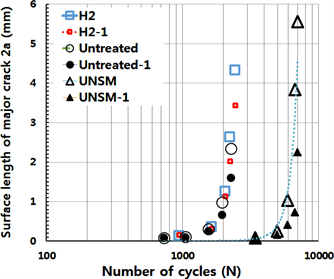
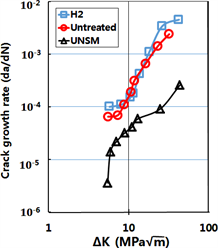
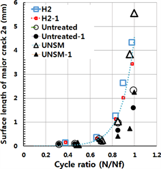
Figure 9. (A) Propagation behaviors of surface fatigue cracks initiated on the smooth-surfaced AISI 304 stainless steel specimen. (B) 2a-N/Nf curves on the smooth-surfaced of AISI 304 stainless steel specimens. (C) Da/dN vs ΔK curves of small surface fatigue cracks initiated on smooth specimens.
stress intensity factor range (ΔK) of small surface cracks. The two specimens show similar fracture lives and stress levels, the influence of hydrogen embrittlement is less in the fatigue life, and shows a similar growth behavior as that for the untreated material. These growth characteristics are closely related to which both the fatigue endurance limits of the untreated material and that of the hydrogen-embrittled material show in the same way.
3.4.3. Observation of Fatigue Cracks on the Surface of Specimens before Fracture
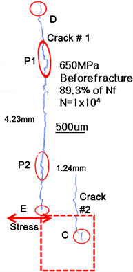
Figure 10 shows eight SEM micrographs 100x magnification of the surface of the hydrogen-embrittled specimen (650 MPa, N = 1 × 10⁴); subsequently, cracks were created on the surface of the test piece using a sketch technique [19] [20] to
Figure 10. The images were duplicated by tracing the surface crack on the hydrogen-embrittled specimen (650 MPa, N = 1 × 10⁴).
discriminate with the naked eye, is shown in reduced form. In this figure, the major crack (crack # 1) of DE is 4.23 mm long and the small crack (crack # 2) of C is approximately 1.24 mm long.
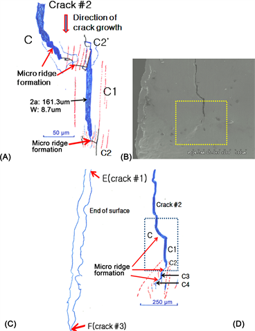
Figure 11(A) is 500 times magnified C displayed by circle in Figure 10. For clarity, Figure 12(A) shows a sketch when N = 1 × 10⁴ before breakage of the specimen. This figure shows the merging process of the surface cracks. The diagram explains that the cracks are initiated by shear separation along the slip line, which is indicated by the dotted line in the figure, and the cracks gradually grow and coalesce. In this figure, at the tip of crack, many micro surface cracks initiate, grow, and combine with each other. The schematic diagram in Figure 12 shows the crack occurrence. Figure 11(B) shows the small surface cracks (2a: 69.3 um) that are initiated in other places. These small surface cracks are observed several times on the entire surface of the specimen.
Figure 11(C) shows a low magnification SEM micrograph (25×), before specimen fracture at N = 1 × 10⁴ cycles, to grasp the position of the surface crack of the whole test piece, including Figure 10. This figure shows two major cracks (labeled by crack # 1 and crack # 3) and one crack (crack # 2). Figure 14(A) shows a cross-sectional photograph of a temper colored optical image of the test piece that shows crack # 1 and crack # 3. However crack # 2 did not merge into cracks # 1 and # 3; therefore crack # 2 is not displayed in this optical image. Figure 10 shows the size and position of crack # 2, and C, E, and F in the figure indicate the crack tips. As described above, many surface cracks are unobservable
Figure 11. Characteristics of initiation, growth and coalescence of the micro-crack tips. (top) A typical example of initiation and coalescence of a small surface crack (marked as C in Figure 10). (middle) An example of initiation of a small surface crack. (bottom) SEM image of three cracks at 25× magnification before fracture.
in the enlarged photograph of hydrogen-induced AISI 304 stainless steel, as observed for Inconel 718 [2] and AISI 316 L [3] .
Therefore, the SEM image of the surface observation indicates that the fatigue strength according to hydrogen embrittlement of the AISI 304 stainless steel used in this study does not gradually decrease with the stress level. Therefore, the sensitivity of AISI 304 stainless steel to hydrogen gas is low. The SEM micrograph of the fractured surface of the material used in this study shows that fish-eye cracks, which were widely observed in VHCF are not observed [9] [15] [16] .
3.4.4. Initiation, Growth, Coalescence, and Micro Ridge Formation Model of Surface Fatigue Cracks
Figure 12(A) and Figure 12(C) are schematically shown using the sketch technique [19] [20] to determine the initiation, growth, coalescence, and micro ridge formation behavior of surface cracks using SEM micrographs of high magnifications from Figure 11(A) and Figure 12(B), respectively.
Figure 12(A) is a sketch of the SEM micrograph using before breakage of the specimen N = 1 × 10⁴ (89.3% of Nf). C (2a: 1.24 mm) on this figure is the surface of crack # 2 and sketches the process of merging with the adjacent small surface crack, C1 (2a: 161.3 µm, w: 8.7 µm). This schematic diagram shows that cracks C and C1 coalesce while forming micro ridges. That is, to coalesce with adjacent crack C1, many slip lines (indicated by dashed lines) form between cracks C and C1. The micro-ridge formation and coalescence process of the slip line is shown in Figure 12(A). These micro ridges form the asperity of the fracture surface, and form roughness-induced cracking [21] [22] [23] [24] . After merging of the cracks, the coalesce process of crack tips C2 and C2’ of the C1 crack take on a very similar form as that for the coalescence of C and C1. Additionally, the ellipses displayed at P1 and P2 in Figure 10 adopted the crack coalescence form (like Figure 12(A)).
Figure 12(B) shows an SEM micrograph with a magnification of 100x after breaking the specimen at Nf = 1.12 × 10⁴. Figure 12(C) shows a sketch of the image in Figure 12(B); its position is indicated by the dotted rectangle in Figure 10. Additionally, Figure 12(C) is a sketch of Figure 12(B).
The left two lines in Figure 12(C) show the fracture surfaces that formed by combining E (crack # 1) and F (crack # 3). The dotted rectangle in Figure 12(C) is the cycles of N = 1 × 10⁴ (89.3% of Nf) and this is the same data as that in Figure 12(A). However, the width of crack C increases while forming micro ridges between C and C1 during the rotation 1200 additional cycles. Additionally, C2 in Figure 12(C) grows to become larger than C2 of Figure 12(A). The new C3 and C4 micro-cracks are initiated by a slip that occurs at the C2 tip, showing growth and coalescence to form micro ridges. The initiations of two micro cracks are shown by the arrows in the SEM micrograph (Figure 12(D)).
Figure 12(D) is an SEM micrograph that shows an enlarged view of the crack tip, which is indicated by the dotted rectangle in Figure 12(B). Features C1 to C4 in Figure 12(C) are shown in the same way in Figure 12(D).
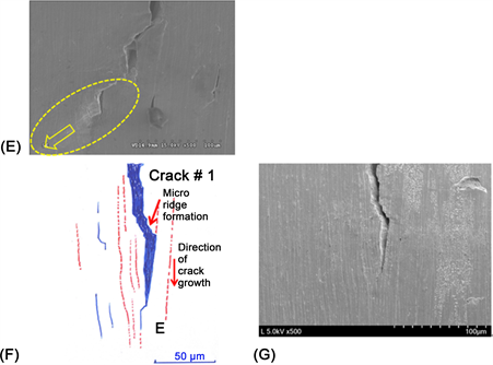
The dotted ellipse and the arrow in Figure 12(E) show the direction of the large-scale plastic deformation flow and concentration phenomenon for merging
Figure 12. Illustrated figures and SEM images at crack-tips C and E. (A) Sketch of crack C at N = 1 × 10⁴ (before fracture), (B) SEM image (100×) of the sketch shown in (c), (C) sketch of crack C2 at Nf = 1.12 × 10⁴ (after fracture), (D) SEM image (250×) of crack C2 at Nf = 1.12 × 10⁴, (E) SEM image (500×) of crack tips C3 and C4, (F) sketch of crack E at N = 1× 10⁴, and (G) SEM image of figure (F) (500×).
with the major crack while enlarging the crack tip (500× SEM image in Figure 12(D)).
Figure 12(F) shows a sketch of the enlarged E portion of the major crack when N = 1 × 10⁴. Figure 12(F) also shows that the surface crack initiates, grows, and coalesces, as shown in Figure 12(A) and Figure 12(C), and forms micro ridges. Figure 12(G) shows a SEM image of the region in Figure 12(F).
We propose a surface crack initiation, growth, coalescence, and micro ridge formation model as a diagrammatic view of the series of surface observations after fracture and before fracture of the specimen (Figure 13). 1) A slip line like a dotted line is formed perpendicular to the principal stress; 2) a slip line becomes micro-crack from tearing. 3) The width of this crack increases and the crack tip becomes blunted while growing. 4) The blunted crack tip re-forms a slip line because of deformation in the shear direction around the crack tip. 5) Then, the crack grows in the shear direction, forms micro ridges, and merges with adjacent cracks. The actual models of the initiation, growth, coalescence, and micro ridge formation processes of these small surface cracks are shown in Figure 12, and micro ridges are formed at the time of coalescence. The initiation of surface cracks, such as C ⇒ C 1 ⇒ C 2 ⇒ C 3 ⇒ C 4, and the process of growth and coalescence while forming micro ridges are repeated continuously, and the specimen reaches rupture cycles.
3.4.5. SEM Observations of Fatigue Fracture Surface
Figure 14(A) is a close-up micrograph that characterizes small surface cracks in the inner direction just before fracture of the specimen (89.3% of the fracture life). To observe surface and depth shapes of the small surface cracks, the specimens show Figures 10-12 were temper color treated at 550˚C for 2 h and photographed using an optical camera with a macro lens. In this photograph, the characteristics of the initiation position of crack # 1, crack # 3, and the well-grown
Figure 13. The surface crack initiation, growth, coalescence, and ridge formation model proposed in this research.
Figure 14. The fractography of a small surface crack on the hydrogen-embrittled specimen (650 MPa, Nf = 1.12 × 10⁴). (A) Optical image, (B) SEM image (30×), (C) SEM image (50×) of G, and (D) SEM image (100×) of H.
fracture surface are represented by the tempering color method. The two arrows for crack #1 and one arrow for crack #3 show the growth position of each crack in the image. Points E and F in this image correspond to points E and F in Figure 11(c). Additionally, D indicates the same crack tip that shown in Figure 10.
Figure 14(B) shows a SEM micrograph at a low magnification (25×), which is the same object as that shown in Figure 14(A). The shape of the depth direction of the crack growth can be distinguished in the optical image after the temper color treatment (Figure 14(A)); however it is impossible to identify these features in the SEM micrograph (Figure 14(B)). The main locations (D - H) of each crack are also shown in this SEM micrograph (Figure 14(A)).
Figure 14(C) shows an expanded display of the origin of crack #1 (marked as G), and the two points indicated by arrows are the origin of the major crack. In addition, a small, nearby crack is also initiated, and the cracks initiate, grow, coalesce and form micro ridge as in the model of Figure 13. Figure 14(D) is an enlarged view of the origin of crack #3 (marked as H). One point indicated by the arrow is the origin of the main crack and it has grown and coalesced.
4. Conclusions
The following conclusions were obtained by various experiments for characterizing the influence of hydrogen-embrittled on the fatigue behaviors of the two AISI 304 stainless steel specimens at room temperature. The test specimens were untreated and hydrogen-embrittled material (10 MPa, 300˚C, 120 h).
1) The hydrogen-embrittled material showed almost the same tendency as S-N curve and the fatigue strength, even though the specimen contained about 8.1 times more hydrogen than the untreated material. In other words, the sensitivity of AISI 304 stainless steel to hydrogen gas was relatively low; the effect of hydrogen gas was less than that for the Inconel 718 material. The fatigue limit of the S-N curves of the hydrogen-saturated material appeared at approximately 400 MPa.
2) In illustrative diagrams from continuous observation of the specimen surface, we can propose a surface crack initiation, growth, coalescence, and micro ridge formation model. A slip line is formed perpendicular to the principal stress. And tearing process occurs, and the slip line becomes a crack. At this time the width of the crack increases and the crack tip is blunted while growing. This blunted crack tip forms many slip lines because of the deformation in the shear direction around the crack with a large crack width. And in the shear direction, the crack grows, forms micro ridges, and merges with adjacent cracks. And micro ridges are formed during coalescence between the cracks. The initiation, growth, coalescence, and micro ridge formation model of surface cracks such as C ⇒ C1 ⇒ C2 ⇒ C3 ⇒ C4 are repeated continuously, and the test piece is broken while forming micro ridges.
Acknowledgements
“This research was supported by Development of Reliability Technology of Standard Measurement for Hydrogen Convergence Station funded by Korea Research Institute of Standards and Science (KRISS - 2017 - GP2017-0014)” and “This work was supported by the 2018 Yeungnam University Research Grant”.
Cite this paper
Nahm, S.-H., Shim, H.-B., Baek, U.-B. and Suh, C.-M. (2018) Very High Cycle Fatigue Behaviors and Surface Crack Growth Mechanism of Hydrogen-Embrittled AISI 304 Stainless Steels. Materials Sciences and Applications, 9, 393-411. https://doi.org/10.4236/msa.2018.94027
References
- 1. Shin, H.S., Kim, K.H., Back, U.B. and Nahm, S.H. (2011) Development of Evaluation Technique for Hydrogen Embrittlement Behavior of Metallic Materials Using In-Situ SP Testing under Pressurized Hydrogen Gas Conditions. Transactions of the Korean Society of Mechanical Engineers A, 35, 1377-1382. https://doi.org/10.3795/KSME-A.2011.35.11.1377
- 2. Suh, C.M., Nahm, S.H., Kim, J.H. and Pyun, Y.S. (2016) A Study on the VHCF Fatigue Behaviors of Hydrogen Attacked Inconel 718 Alloy. Transactions of the Korean Society of Me-chanical Engineers A, 40, 637-646. https://doi.org/10.3795/KSME-A.2016.40.7.637
- 3. Nahm, S.H., Baek, U.B., Suh, C.M. and Pyun, Y.S. (2017) Study on VHCF Fatigue Behaviors and UNSM Effects of Hydrogen Attached STS 316L. Transactions of the Korean Society of Mechanical Engineers A, 41, 1011-1020. https://doi.org/10.3795/KSME-A.2017.41.11.1011
- 4. Bechtle, S., Kumar, M., Somerday, B.P., Launey, M.E. and Ritchie, R.O. (2009) Grain-Boundary Engineering Markedly Reduces Susceptibility to Intergranular Hydrogen Embrittlement in Metallic Materials. Acta Materialia, 57, 4148-4157. https://doi.org/10.1016/j.actamat.2009.05.012
- 5. Cotterill, P.J. and King, J.E. (1991) Hydrogen Embrittlement Contributions to Fatigue Crack Growth in a Structural Steel. International Journal of Fatigue, 13, 447-452. https://doi.org/10.1016/0142-1123(91)90478-H
- 6. Bruchhausen, M., Fischer, B., Ruiz, A., Gonzalez, S., Hahner, P. and Soller, S. (2015) Impact of Hydrogen on the High Cycle Fatigue Behavior of Inconel 718; a Symmetric Push-Pull Mode at Room Temperature. International Journal of Fatigue, 70, 137-145. https://doi.org/10.1016/j.ijfatigue.2014.09.005
- 7. Kouters, M.H.M., Slot, H.M., van Zwieten, W. and van der Veer, J. (2014) The Influence of Hydrogen on the Fatigue Life of Metallic Leaf Spring Components in a Vacuum Environment. International Journal of Fatigue, 59, 309-314. https://doi.org/10.1016/j.ijfatigue.2013.09.013
- 8. Karsch, T., Clausen, B. and Zoch, H.W. (2014) Influence of Hydrogen and Deoxidation Technique on the Fatigue Behaviour of Steel SAE 52100 in the VHCF Regime. 6th International Conference on VHCF, Chengdu, 15-18 October 2014.
- 9. Suh, C.M., Lee, M.H. and Pyoun, Y.S. (2010) Fatigue Characteristics of SKD-61 by Ultrasonic Nanocrystal Surface Modification Technology under Static Load Variation. International Journal of Modern Physics B, 24, 2645-2650. https://doi.org/10.1142/S0217979210065404
- 10. Suh, C.M., Song, G.H., Suh, M.S. and Pyoun, Y.S. (2007) Fatigue and Mechanical Characteristics of Nanostructured Tool Steel by Ultrasonic Cold Forging Technology. Materials Science & Engineering A, 443, 101-106.
- 11. Roland, T., Retraint, D., Lu, K. and Lu, J. (2006) Fatigue Life Improvement through Surface Nanostructuring of Stainless Steel by Means of Surface Mechanical Attrition Treatment. Scripta Materialia, 54, 1949-1954. https://doi.org/10.1016/j.scriptamat.2006.01.049
- 12. Dai, K. and Shaw, L. (2008) Analysis of Fatigue Resistance Improvements via Surface Severe Plastic Deformation. International Journal of Fatigue, 30, 1398-1402. https://doi.org/10.1016/j.ijfatigue.2007.10.010
- 13. Tian, J.W., Villegas, J.C., Yuan, W., Fielden, D., Shaw, L., Liaw, P.K. and Klarstrom, D.L. (2007) A Study of the Effect of Nanostructured Surface Layers on the Fatigue Behaviors of a C-2000 Superalloy. Materials Science & Engineering A, 164-168. https://doi.org/10.1016/j.msea.2006.10.150
- 14. Wang, T., Wang, D.P., Liu, G., Gong, B.M. and Song, N.X. (2008) Investigations on the Nanocrystallization of 40 Cr Using Ultrasonic Surface Rolling Processing. Applied Surface Science, 255, 1824-1828. https://doi.org/10.1016/j.apsusc.2008.06.034
- 15. Gill, A., Telang, A., Mannava, S.R., Qian, D., Pyun, Y.S., Soyama, H. and Vasudevan, V.K. (2013) Comparison of Mechanisms of Advanced Mechanical Surface treatments in Nickel-Based Superalloy. Materials Science & Engineering A, 576, 346-355. https://doi.org/10.1016/j.msea.2013.04.021
- 16. Pyun, Y.S., Kim, J.H., Suh, C.M., Cho, I.S., Oh, J.Y., Wang, Q. and Khan, M.K. (2014) The Rotary Bending Fatigue and Ultrasonic Fatigue Performance of Ti-6Al-4V ELI and STA Alloys after Ultrasonic Nanocrystal Surface Modification Treatment. 6th International Conference on VHCF, Chengdu, 5-18 October 2014.
- 17. Sakai, T., Murase, T., Yoshiyama, S., Torimaru, T. and Takeda, M. (2004) Rotating Bending Fatigue Property of Structural Steels Having Different Strength Levels in Gigacycle Regime. Proceedings of 3rd International Conference on Very High Cycle Fatigue, Kusatsu, Japan, 16-19 September 2004, 641-648.
- 18. Kitagawa, H., Takahashi, S., Suh, C.M. and Miyashita, S. (1979) Quantitative Analysis of Fatigue Process: Microcracks and Slip Lines under Cyclic Strains. ASTM STP, 678, 420-449.
- 19. Suh, C.M., Yuuki, R. and Kitagawa, H. (1985) Fatigue Microcracks in a Low Carbon Steel. Fatigue & Fracture of Engineering Materials & Structures, 8, 193-203. https://doi.org/10.1111/j.1460-2695.1985.tb01203.x
- 20. Suh, C.M. and Kitagawa, H. (1987) Crack Growth Behaviour of Fatigue Microcracks in Low Carbon Steels. Fatigue & Fracture of Engineering Materials & Structures, 9, 409-424. https://doi.org/10.1111/j.1460-2695.1987.tb00468.x
- 21. Kitagawa, H., Nakasone, Y. and Shimodaira, M. (1985) A Fracture Mechanics Study of the Corrosion Fatigue of a Structural Steel with a Surface Defect. Transactions of the JSME Series A, 51, 1026-1033.
- 22. Nahm, S.H. and Suh, C.M. (1997) Observation on the Growth Behavior of Small Surface Cracks Using Remote Measurement System. ASTM STP, 1318, 71-84. https://doi.org/10.1520/STP11893S
- 23. Jung, H.G. (2011) Hydrogen Embrittlement Phenomenon of Steel Materials. Journal of the Korean Society of Mechanical Engineers, 51, 42-44.
- 24. Suh, C.M., Suh, M.S. and Hwang, N.S. (2012) Growth Behaviours of Small Surface Fatigue Crack in AISI 304 Steel. Fatigue & Fracture of Engineering Materials & Structures, 35, 22-29. https://doi.org/10.1111/j.1460-2695.2011.01623.x


