Materials Sciences and Applications
Vol.4 No.10(2013), Article ID:38125,16 pages DOI:10.4236/msa.2013.410075
Coronary Stents Fracture: An Engineering Approach (Review)
![]()
1Department of Mining and Materials Engineering, McGill University, Montreal, Canada; 2Department of Mechanical Engineering, McGill University, Montreal, Canada.
Email: *balmangour@gmail.com
Copyright © 2013 Bandar AL-Mangour et al. This is an open access article distributed under the Creative Commons Attribution License, which permits unrestricted use, distribution, and reproduction in any medium, provided the original work is properly cited.
Received July 26th, 2013; revised August 27th, 2013; accepted September 12th, 2013
Keywords: Stent; Restenosis; Mechanical Properties; Strut Thickness; Coatings
ABSTRACT
With the invention of coronary stent, promising clinical outcomes appeared. However, the long-term success of stent has been beaten by significant in-stent restenosis and consequently stents fractures (SF). Cardiologists have been looking on SF as a threat to patients’ life because it is associated with shortand possibly long-term morbidity rate. In this review, stent materials and properties from the perspective of materials engineering and clinical drivers are discussed. The review also outlines how stent materials and design have evolved with time. Opinions are given as to the merit and direction of various on-going and future developments.
1. The Potential Need for Coronary Stents and the Early History
Globally, cardiovascular diseases are the leading cause of death and serious illness accounting for 30% of the deaths worldwide annually [1]. Forty years ago, coronary artery bypass surgery (CABG) was the popular revascularization treatment used to treat obstructive coronary artery diseases [2,3]. However, it was claimed that frequent coronary closures occurred and hence emergency surgical revascularization was necessary [2,4]. Consequently, CABG was more or less abandoned. Subsequently, extensive developments have been made in less invasive cardiology treatments, with Plain Old Balloon Angioplasty (POBA) being one of the most frequent treatment performed, in clinical practice [2,5]. Although POBA was an innovative treatment, its success was also hindered by the problems of acute vessel blockages [2,5, 6].
These problems lead to the birth of a second revolutionary treatment of an expandable metal mesh tube inserted in the blocked coronary artery which is called a stent [6,7]. It has been reported that restenosis rate dropped significantly after implementing stents from 30% - 40% to approximately 20% [8]. The number of percutaneous coronary intervention (PCI) performed each year has expanded considerably since 1980s [1,7]. For example, angioplasty procedures doubled in Europe between 1992 and 1996 [7]; while over than 600,000 percutaneous coronary revascularizations were performed in the United States in 1997. These innovative devices were quickly embraced by cardiologists [2,8,9], and now it is involved in more than 85% of coronary intervention procedures, with increasing numbers of patients being treated each year [2]. Indeed, interventional cardiologists are faced with extensive choices of coronary stents to implant. This choice ranges start from different alternative material of bare-metal stents (BMS) and drug eluting stents (DES) that are broadly used in current practice to newer stents such as biodegradable stents [1,7]. The primary markets for stents have been optimizing the stents with new manufacturing technologies. Currently, there are four main on-going optimizations of stents: 1) prevention of acute blockages within the stent, 2) reduction of the profile of the implant to the smallest possible size in order to minimize the invasiveness of the procedure and to allow access to the most narrow locations, 3) increase in stent durability in severe environmental locations where the biomechanical forces creates material fatigue challenges, 4) enhance stent radiopacity i.e. can be easily seen under X-ray visualization techniques.
2. The Stents Fractures Problem
Although the use of stents in coronary intervention procedures are adopted worldwide, several patients exhibits in-stent restenosis (ISR) due to the thick accumulation of vascular tissue after stent being placed [4,6,10,11], leading to late thrombosis and stents fractures (SF). Initial reports have referred to stents fracture as being an undesirable event and life threatening [12-14]. Indeed, there is mounting evidence that relates complete SF with ISR and thrombosis, and consequently stent functional failure and potential adverse effects [14-16].
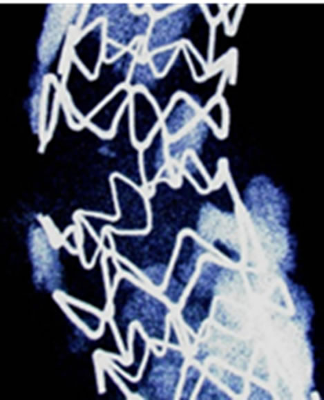
Clinically speaking, the incidence of stents fractures (Figure 1) is reported in 1% - 2% of patients [10,14,17, 18] at 8- to 10-month follow-up angiography. Higher rates (up to 29%) are reported based on pathologic investigations (i.e. SF are assessed when patient is dead) [10]. Other early-stage fractures of stents have been reported in other study of nitinol femoral stents, where 37.2% of stents (45 of 121) fractured within 10.7 months of implantation, as detected by X-ray examination. However, because of limited visibility of angiography to detect fractures, its true incidence is still unknown [10,15]. Although numerous clinical statistics and studies have been performed, each study has its own criteria, setting objectives and study limitations [4,15,18]. The fracture of the stents could be with single strut fracture, or could be with more detailed classifications; i.e. moderate fracture (more
 (a)
(a)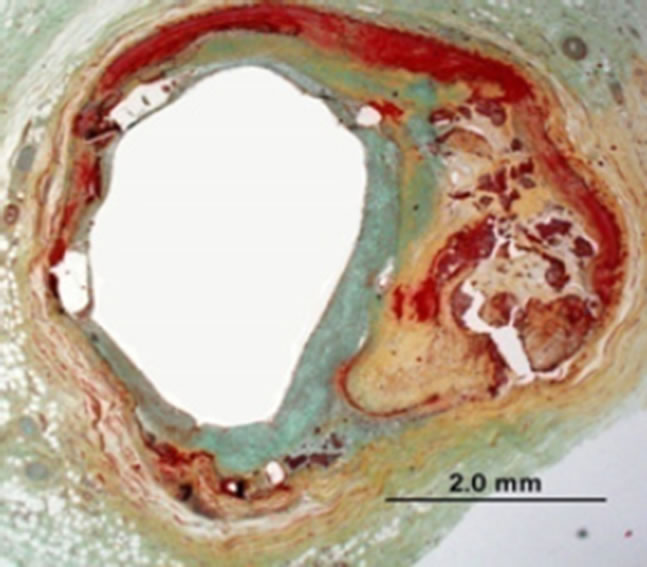 (b)
(b)
Figure 1. (a) Stent fracture associated with restenosis; (b) Radiograph showing clogged vessel artery after stenting [10].
than one strut fracture), or severe fracture (complete separation of stent segments) (Figure 2) [4,10]. Therefore the findings may not be statistically representative of all patients who receive stents [10].
Unfortunately, most of the research work on stent fracture was either medical statistics and/or from clinical point of view. A deep understanding of the science and engineering behind the technology of stents is necessary before their implementation in practice. In this review, the objective is to review stent materials and properties from materials engineering point of view, relevant to
 (a)
(a) (b)
(b) (c)
(c)
Figure 2. (a) Single strut fracture; (b) Two or more strut fractures without deformation; (c) Two or more strut fractures with deformation [10].
stent function, mainly strength, ductility, fatigue and corrosion resistance. This review also describes the evolution of the current new stent design and the future perspective of this field, hoping to solve the stents fractures problem. Therefore, this review is intended to provide the reader with an overview of the key concepts that will help the assessment of new technology. Worthwhile to mention, only the bare-metal stents are considered in this review.
3. General Property Requirements for Stents
It is very important to understand the ideal properties of stents before evaluating its fractures. In general, medical implants are made of not only metals but also ceramics, polymers, and composites. Although ceramics are strong, they lack both elasticity and plasticity. Moreover, ceramics are usually brittle with low fracture toughness. Polymers, on the other hand, have higher elasticity but lack strength and stiffness. However, it is difficult to obtain polymers with both high elasticity and strength at body temperature. Moreover, stents procedures require X-ray imaging, which is controlled by the atomic number and density of the compositional elements of a stent. Since polymers consist of light elements, it cannot be used without any improvement of the material; this is essential in order to identify the stent fractures earlier through X-ray. Hence, these drawbacks limit the use of polymers in stents. Therefore, from the viewpoint of mechanical properties and visibility on X-ray imaging, metals are the main materials utilized for stents. Interestingly, the effort to substitute polymers for metals in stents is currently on-going [19,20]; however, improvement of the mechanical and imaging properties of polymers are necessary.
Generally speaking, the ideal stent would be vascular biocompatible, corrosion resistant, radiopaque, and wellsuited mechanical properties. Since stents are tubes used for dilatation to counteract decreases in blood vessels; therefore, elasticity and plasticity for expansion and rigidity for the maintenance of dilatation and resistance to elastic recoil are required. In fact, a high elastic modulus [7,21] is needed to prevent stent recoil, while low yield strength is preferred to allow stent expansion at acceptable balloon pressures and assists insertion of the stent with the delivery system, which is a catheter. High tensile strength helps to achieve sufficient radial strength after expansion with a minimum stent volume [7,21-23]. Indeed, higher tensile strength helps to design stents with thinner struts, and hence improving flexibility, deliverability, and access to smaller vessels [23]. Moreover, a high degree of ductility [21,24] is compulsory to withstand deformation during expansion. Finally, the ratio of yield strength to modulus of elasticity [21] is of particular interest for stent designer to characterize the elastic range of the materials, which affects acute recoil and radial strength. Table 1 summarizes the main physical and mechanical properties for common biomaterials. Conventional metals cover these properties when the correct metals are selected. However, the ideal combination of mechanical properties, discussed above, is difficult to obtain, and therefore a careful compromise needs to be found. Stainless steel 316L, nitinol, and cobalt chromium alloy L605 are well-known in the biomedical field, and one of their biomedical applications is coronary stents [7,24,25]. They are characterized by their excellent corrosion resistance, high ductility, and high modulus of elasticity. Although titanium alloys have superior corrosion resistance and excellent biocompatibility, it is not a good choice in stent application because of its low ductility, low strength and poor density, the latter being an imaging issue [25].
Figure 3 shows an example of the fatigue limits of selected biomaterials [26]. As shown in Figure 3, the fatigue limits decreases in the following order: Co-Cr alloy followed by Ti-6Al-4V then 316L stainless steel. However, the limit of each material depends on the fabrication process, surface condition and microstructure, thus showing a fairly large range for some of the metals [e.g. CP (commercial purity) Ti].
Table 2 list some of the biomaterials used in the stents along with their leading manufacturing company. Generally, the metals commonly used for manufacturing baremetal stents are 316L stainless steel, nitinol (Ni-Ti), cobalt-chromium (Co-Cr) alloys, platinum alloys, tantalum (Ta). These are briefly discussed below.
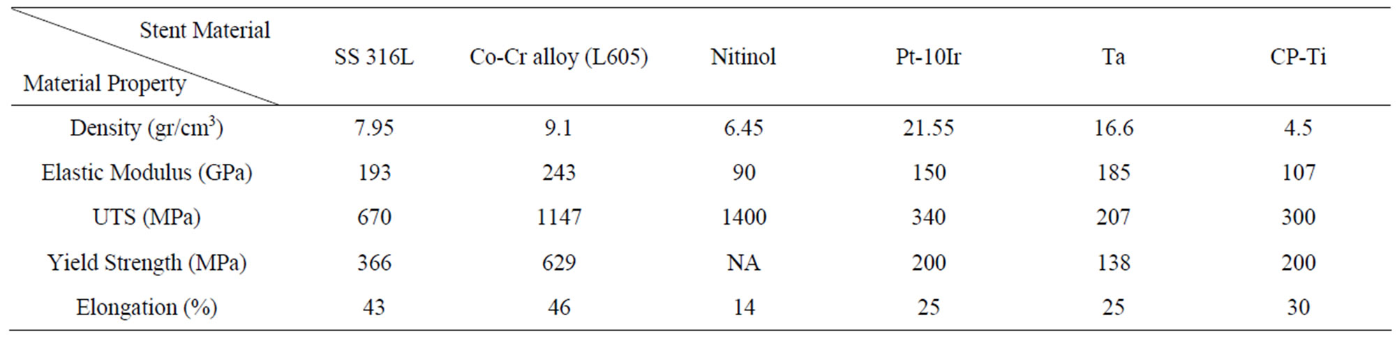
Table 1. Physical and mechanical properties of selected biomaterials.
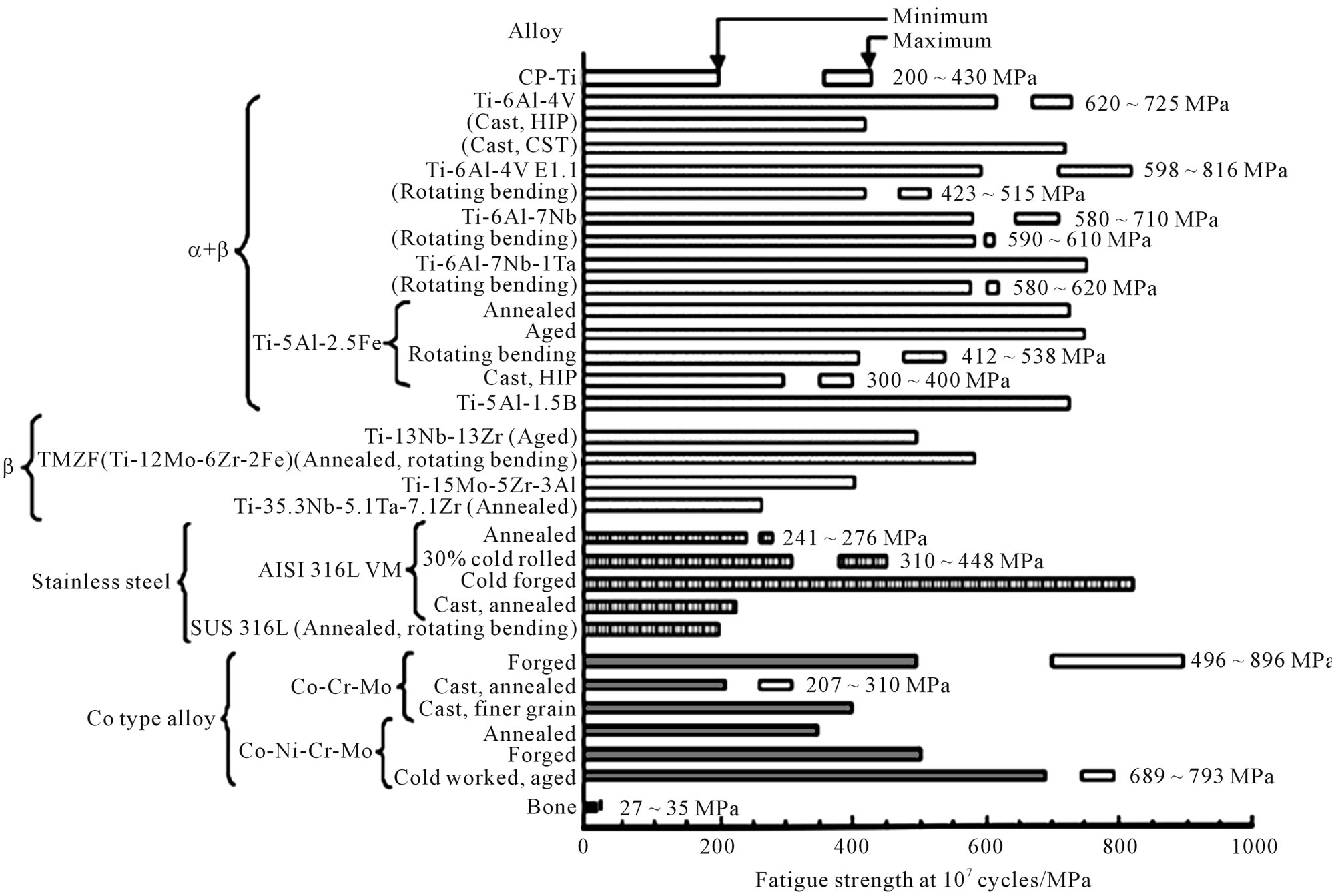
Figure 3. Fatigue strength at 107 cycles of biomedical materials [24].
Table 2. Commonly used stent materials along with their manufacturing company.
3.1. Stainless Steel
Stainless steels are iron based alloys with main elements of Cr and Ni. Elements such as Ni, Mo, Ti, Nb, and N are added in some grades of stainless steels to improve their corrosion resistance, heat resistance, strength, and workability [27]. However, the microstructure, strength, and corrosion resistance of stainless steels depend mainly on the concentrations of Ni and Cr. Stainless steels do not corrode in an oxygen containing atmosphere, however, they may corrode locally and form pits in chloride solutions as found in human body. Stainless steels are classified, according to the crystal phase, as ferritic, martensitic, or austenitic types [27]. Because austenitic stainless steel does not have high strength, they are strengthened by cold working and heat treatment and sometimes by the addition of N. Austenitic stainless steel have superior corrosion resistance; the addition of Mo improves the corrosion resistance due to the increases in the stability of the passive film [28]. The main reason for the use of austenitic stainless steels, beside the superior corrosion resistance, is the good balance of strength and ductility, which facilitates the manufacture of the stent, the plasticity for balloon expansion, and to resist the elastic recoil of blood vessels [29,30].
Austenitic 316L stainless steel, in particular, (“L” means “low carbon content”) has well-suited mechanical properties (Table 1), making it the preferred material for stent application [31]. Its corrosion resistance is improved by adding 2% - 3% of Mo, increasing the Ni content to 12% - 15%, and reducing the carbon content to less than 0.030% [28]. The surface oxide film consists of oxide species of Fe, Cr, Ni, Mo, and Mn, and its thickness is about 3 - 4 nm [28,32]. The surface oxide changes into iron and chromium oxides when a small amount of molybdenum oxide is present in the human body. Unfortunately, carbon forms carbides at the grain boundaries, which reduces the corrosion resistance of the grain boundary [28]. Therefore, even with these improvements, 316L stainless steel may corrode when implanted in the human body [33,34]. Other clinical problem of using 316L stainless steel are its ferromagnetic nature (i.e. minimum of 60% pure Fe) and low density [31]. These features make stainless steel a problematic in the clinic for poorly visible images in the MRI [31]. Also, biocompatibility is another issue with stainless steel stents [35]. As the average weight percentage of Ni in 316L stainless steel is 12%, release of nickel may occur causing allergic reactions in the human body [36,37]. Indeed, the release of Ni, Cr, and Mo ions from stainless steel stents may induce local immune response and inflammatory reactions, which in turn may result in in-stent restenosis [35]. Stainless steel stents composed of low Ni concentration (4.5% - 9%) can reduce the concern of allergic reactions to Ni [35]. However, higher Ni concentration (10% - 14%) can be beneficial in decreasing the ferromagnetic properties of stainless steel. The addition of Ti (about 0.4%) in the stainless steel makes them even more attractive. Indeed, a variety of coating materials have been used to coat 316L stainless steel stents, in order to increase its visibility and to improve its biocompatibility by preventing the release of ions from the stent surface (i.e. anti-corrosion characteristics) [34].
3.2. Ni-Ti Alloy (Nitinol)
The Ni-Ti alloy, known as Nitinol, consists of roughly equal atomic amounts of Ti and Ni and shows unique mechanical properties such as shape memory, and superelasticity. In the shape memory effect, a deformed shape is returned to the original shape by heating; in superelasticity, apparent plastic deformation is returned to the original shape by the release of load [38-40]. Indeed, shape memory alloys, are capable of undergoing a more large degree of elastic deformation and strain before reaching their yield strength [38-42]. Nitinol undergo plastic deformation at room temperature (i.e. martensitic phase) and crimped on to the delivery system [42]. The transformation temperature itself is influenced by the composition, impurities, and heat treatments [43]. Because of these unique properties, the nitinol is used for stents [42]. Self-expanding stents have a smaller diameter at room temperature and expand to their current diameter at body temperature. After implantation it regains its original shape and conforms to the vessel wall because of the increase in temperature inside the body [43]. The maximum strain recovery is about 8.5% after plastic deformation; nitinol also has suitable mechanical properties. However, the nitinol stent may corrode [44,45], and the release of large amount of Ni ions causes toxic effects to tissues in many cases. Furthermore, imaging of nitinol stent is another concern [46]. Although stent’s radiopacity may not have direct influence on its function, it undoubtedly has an impact on deployment success. The 316L stainless steel stents are more radiopaque than the nitinol stents [47].
3.3. Co-Cr Alloys
Co-Cr alloys have been used extensively in the biomedical domain. Both the Co-Cr alloys platform DRIVER stent and the L-605 (Co-20Cr-15W-10Ni) Guidant MultiLink Vision stent are commercially available [48]. Co-Cr alloys exhibit a high density that helps to have better radiopacity [22-24]; a high elastic modulus limiting recoil [21,22]. The thickness of the struts is a critical issue in designing a stent; hence, the ability to make ultra-thin struts from Co-Cr alloys with increased strength using these alloys is one of their potential attractions [22,23, 49]. Indeed, the thin struts will not only permits a lower profile, smaller stent volume, and improved deliverability with access to smaller vessels, but will also be helpful to reduce the probability of stents fractures [23]. Co-Cr alloys also show outstanding corrosion resistance, and wear resistance. Indeed, the corrosion resistance of Co-Cr alloys is better than those in stainless steel [50]. Because of the carbide in its Co-Cr alloys structure, it has also excellent wear resistance in comparison to stainless steel [50]. For biomedical use, cast Co-Cr alloys, featured with low cast defect, known as Vitallium, resist pitting and crevice corrosion. The strength and ductility of Co-Cr alloys are as high as those of stainless steel, after subsequent heat treatment and cold working.
3.4. Platinum Alloys
With the use of platinum alloys in stents application, both the strength and radiopacity are enhanced. Also, the need to design stents with smaller strut thickness has been achieved resulting in higher strength, using platinum-chromium based alloy [51]. Platinum-chromium alloys show great tensile properties, which can be positively compared with the 316L stainless steel, but with both thin struts and high radiopacity. The microstructure is almost similar to 316L stainless steel, with the chromium oxide contents that provides high corrosion resistance. Moreover, platinum alloys are biocompatible and support endothelialisation as 316L stainless steel [51].
Other platinum alloy grade used for making stents and successfully implanted in animal models is an alloy composed of 90% Pt and 10% Ir [52,53]. With the presence of iridium, these stents showed improved radiopacity, in comparison to the 316L stainless steel [52]. Indeed, it is even possible to take the 3D image of these stents using MRI [54], where the artifacts produced by the Pt-Ir alloy in MRI are much lower in comparison to the 316L stainless steel stents. However, while these alloys show excellent corrosion resistance, their poor mechanical properties is still a concern [55]. Although a reduction in both thrombosis and inflammatory reactions was noticed using these stents, their recoiling percentage was a bit higher (16%) than the 316L stainless steel stents (5%) [52,53]. While the human clinical trial encouraged the use of Pt-Ir alloys stents as effective and biocompatible [56], the research on the Pt-Ir alloys stents remains limited.
3.5. Tantalum
Tantalum exhibits low magnetic susceptibility and high density making it outstanding X-ray imaging material. Also, Ta has excellent corrosion resistance in a biological environment because of its highly stable surface oxide layer [57,58], where Ta2O5 act as a passive film formed on Ta surface. Tantalum has been coated on 316L stainless steel stents to improve its corrosion resistance, and thus improving its biocompatibility. It is an MRI compatible material as it produces no significant artifacts because of its non-ferromagnetic features [59]. While the biocompatibility and visibility characteristics of Ta are superior to the 316L stainless steel, the commercial availability of Ta stents is much lower than 316L stainless steel stents. This is mainly because of its poor mechanical properties and high cost [58,60,61]. Tantalum is a ductile metal but because the yield strength of Ta is close to the tensile strength (Table 1), Ta stents have a higher possibility of breaking during deployment. Therefore, the pressure applied for the deployment of these stents is usually low and this might result in recoiling. The recoiling percentage was significantly higher for Ta stents compared with the 316L stainless steel stents [60,61]. Although no Ta-based stents have been approved by the FDA yet, Cordis (Johnson & Johnson, USA) has used a bare-Ta stent in clinical trials and released this stent commercially [62].
4. Assessment of Stent Fractures
4.1. Tubing Characteristics versus Stents Fractures
The majority of stents are manufactured by drawing a very fine tube, followed by laser cutting to manufacture the stent [21]. There are several processing parameters that later significantly affect stent performance [21,24, 63]. Interestingly, complete stent fracture (SF) can be correlated with implant duration (i.e. complete SF may occur with the longest implant duration) [2,64]. This suggests a fatigue phenomenon related with the dynamic loading of the stent due to blood pressure. While fractures in coronary stent seem to be highly attributed to high cycle fatigue, most stent fractures occur in relatively short time periods and are due to the high stress/strain applied to the stent from the pronounced mechanical loading. Although the fracture by fatigue has been addressed by design improvements, it is known that stent manufacturing processes do also affect the fatigue behaviour. In principle, achieving smaller grain sizes is one factor in improving fatigue resistance [21,65]. Conventional thermo-mechanical processes can reduce grain size but only to a certain size, which is often of the order of magnitude of the stent strut cross section. This can lead to poor fatigue performance [21]. The current stent strut cross sections are approximately 100 - 70 µm which allows only for a few grains across, since the material grain size is about 30 - 50 µm, thus affecting its fatigue resistance [18,21,30,66-68]. Indeed, a smaller grain size is recognized in the biomedical domain and has a definite benefit both for strength and wear properties [69]. Furthermore, the conventional fabrication process is associated with relatively large inclusions (15 µm) which later affect the stent performance [21]. Also, the heat of the conventional laser machining is also associated with grain coarsening at the surface of the stent which affect it mechanical properties [21,70,71]. Selection of the cutting technique is extremely important because of the heat generated, which may influence the chemical homogeneity, porosity and micro cleanliness of the stent surface [21,63]. Although the ASTM and ISO standards set limits, these are often not adequate to bring the required safety in a stent application [21]. For example, both ASTM and ISO permit inclusions as thick as 15 μm on a 75 μm stainless steel length [21]. However, such defects are significant when compared with stent struts that can be thinner than 100 μm [21,23]. These inclusions may represent a serious threat for rupture failure upon expansion [21]. Inclusions are becoming even more problematic with the current trend towards stronger materials, reduction in strut dimensions and small vessel stenting [6, 21]. Also, when selecting a cutting source, attention should also be paid to chemical composition homogeneity and its consistency across heats that will favour uniform mechanical properties [21,63]. Consequently, working with small laser spot sizes and short pulse duration, which lead to smaller heat affected zones, is a preferred method.
Other essential key for stent performance is to ensure having an adequate degree of control in the tube drawing process [21,63]. In general, dimensional accuracy and surface finish vary greatly with the tubing process and the type of alloy being drawn [21,63]. Stent thickness uniformity is vital for a smooth deployment of the stent [7,21,23]. Apart, sensitivity to processing parameters is different from material to others. For example, stainless steel shows an average sensitivity to processing parameters compared with Co-Cr alloys or nitinol [21,22]. Fortunately, this sensitivity gives the manufacturer a great opportunity to modify the material properties to the necessary requirements [21]. In addition, surface finish should be compatible with obtaining the desired stent finish after cleaning and electro-polishing steps [21,63]. Indeed, electro-polishing does enhance the corrosion resistance and hence biocompatibility; also edge rounding and the removal of micro cracks and surface imperfections improves the fracture and fatigue behaviour. However, these operations differ among stent manufacturers, depending on the amount of material removal [21].
It is also important to realize that different stent manufacturers have different annealing plan [21,63]. However, the most preferred standard is to laser cut the coldworked material, followed by annealing [21]. This approach help to remove unwanted residual stresses generated during laser cutting [21,63]. Nevertheless, annealing need to be carefully controlled to obtain the desirable mechanical properties and microstructure [21]. For further advanced technology, Y. P. Kathuria [72] and Ankur et al. [30] have discussed the most advanced fabrication techniques, which have been used to manufacture stents.
4.2. Clinical Observations that Contribute to Stents Fractures
Several views were raised in the literatures with regard to the causes of stent fracture. It is assumed that the dynamic biomechanical forces, i.e. bending, torsion, shear, compression, and tension, acting on the superficial artery cause stents fractures [4,73]. One of the common observations is that a high percentage of the fractured stents were long [4] or were deployed in an overlapping way [4, 15]. Most of the fracture in stents occurred around areas of increased rigidity due to the overlapping of metals, which may have formed a fulcrum for metal deformation due to vessel movement. Moreover, Halkin et al. [74] reported cases of SF that cardiac motion and stent overexpansion are significant factors influencing stent integrity after deployment. Min et al. [75], reported a case of SF in which vessel angularity is other relevant factor in SF. In fact, excessive vessel tortuosity causes more bending points during the dynamic changes of the cardiac cycle [4,75], and therefore, stent placement at angulated segments of the vessels showed higher increase in the incidence of SF [4].
4.3. Corrosion and Its Contribution to Stents Fractures
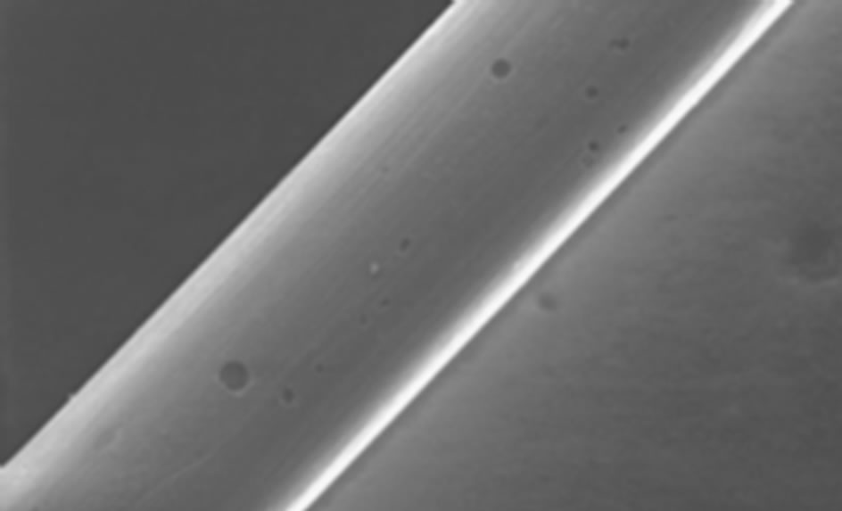
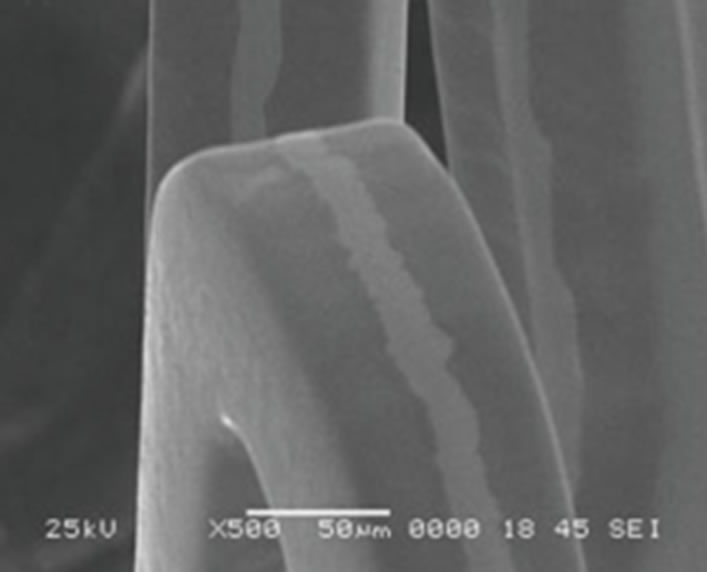
Corrosion may also occur in human body and hence corroded sites may then become initiation sites of a fracture [25,76]. The effects of corrosion in stent are not limited to the loss of integrity of the stents and its function, but also corrosion products can be released and affect the tissue. Figure 4 shows a case of pitting corrosion of a nitinol stent weakening the stent strut and eventually leading to fracture of the stent strut under circulatory pulsation. There are four engineering variables must be taken into account as they influence the corrosion mechanism of stents: 1) composition of the stent-variations within the stent, 2) manufacturing variables; e.g. casting conditions, metal purity, amount of cold-work, degree and type of heat treatment can affect corrosion rates, 3) handling in manufacture, delivery, and insertion affect results. In fact, material handling can have a large impact on corrosion resistance, however, including strategies to modify the protective passive layer. For example, most alloys are typically heat-treated during their construction. This results in the formation of a polycrystalline oxide on the surface of the alloy. Shih et al. [77] demonstrated improved corrosion resistance by removing the manufacturer’s polycrystalline oxide coating and then passivating the nitinol stents to form a novel amorphous oxide. This amorphous oxide layer benefited from an exchange of molybdenum and nickel for ferritin. By decreasing the concentration of ferritin, the breakdown potential of the passive layer is altered and the corrosion resistance is enhanced. Furthermore, this alteration in the material treatment process also resulted in a more uniform coverage of the entire stent without the skip-areas that were seen with the polycrystalline oxide layer. These changes resulted in significant improvements in corrosion resistance, 4) positioning of the stent will affect its local environment and the stresses imposed upon it. Small anatomical differences can also have large differences in pH and potential. In fact, corrosion in blood contact areas is very complex. The abundant oxygen content and continuous flow of electrolytes render most processes highly active. The presence of organic molecules influences corrosion rates and it may affect the surface properties and thrombogenesis. The biological corrosive environment is not constant. This means that oxygen levels and cellular activity vary with time, location, physical activity, and general health status. Indeed, the high concentration of cellular-chloride creates a corrosive environment. Corrosion resistance is controlled by the passivation of a thin layer of surface oxide. This means if a reaction occurs between the environment and the stent metal with the formation of a protective surface oxide layer that protects the underlying structure from further degradation. The composition of this surface layer varies based on the selected material and the manufacturing process. Even nitinol, with its high titanium content, can be prone to corrosion.
One of the most common forms of corrosion in stent is pitting corrosion. It is conditional mostly upon static environments but oxygen depletion is less important. Here, autocatalysis plays an important role in the acceleration
 (a)
(a) (b)
(b)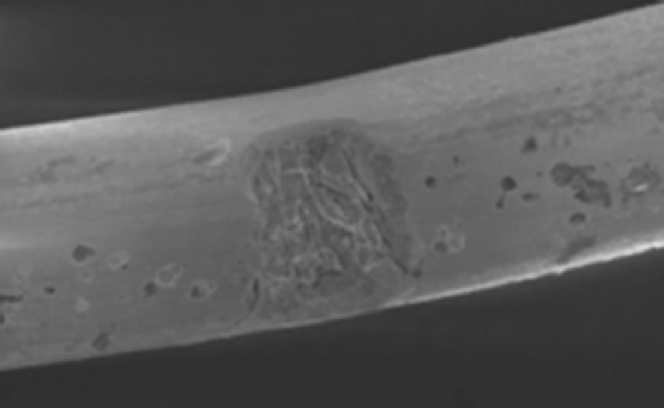 (c)
(c)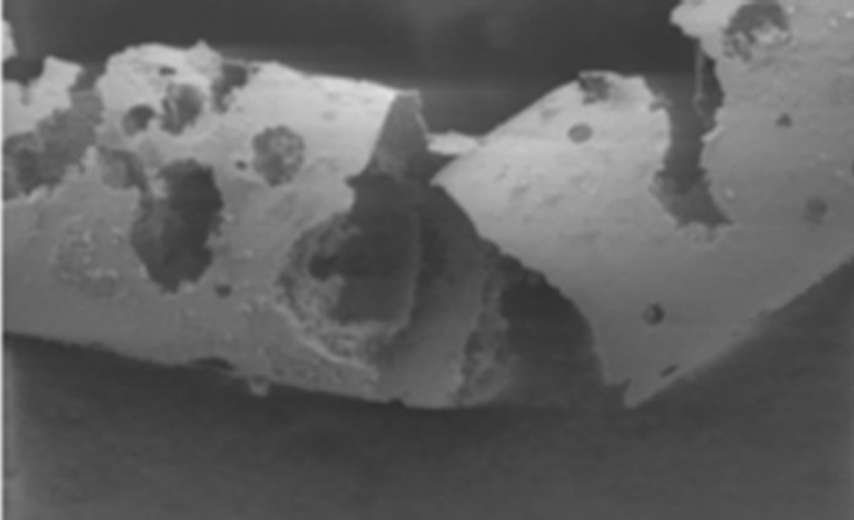 (d)
(d)
Figure 4. Example of multiple corrosion pits of a nitinol wire shown by SEM graph [76].
of corrosion. Scratches, handling damage, and inclusions may initiate this by removing the oxide layer; e.g. Cr2O3 in stainless steel (Figure 5). It usually appears as freckles and grows down in the direction of gravitational field. It is desirable to avoid pits in highly stressed implants such as stents as they act as stress concentrators and may initiate crack propagation. When small they have a frosted appearance, which then become coloured (brown and green) spots. This can result in a large degree of localised damage as the small areas of active corrosion become the anode and the entire remaining surface becomes the cathode.
One of the other common forms is erosion and fretting corrosion. Fretting corrosion is difficult to distinguish from wear but it resembles pitting corrosion except pits are elongated in the direction of flow. An acceleration of attack due to relative movement between the stent and surrounding fluid and increases the rate of attack by the other mechanisms. Flowing solution will remove the corrosion products and provide new dissolved reactants such as chloride ions and oxygen. The accumulation of the products of corrosion at the interface between the metallic stent and solution tends to reduce the rate of reaction. This may disrupt the passive film and produce accelerated corrosion. The passive layer may be removed by a mechanical process either by a scratch that does not repassivate, or under a continuous cyclic loading.
Other familiar form of corrosion in stent is stress corrosion (Figure 6). Tensile stress increases the chemical activity of metals. Stent will be in tension on one side while in compression on the other. This produces an electrochemical potential that renders the convex side anodic with respect to the concave side. This type of corrosion occurs mostly in convex lesions. The formation
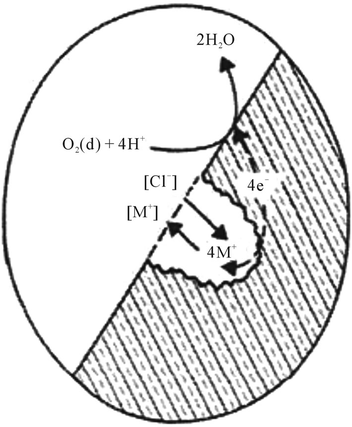
Figure 5. Pitting corrosion mechanism.
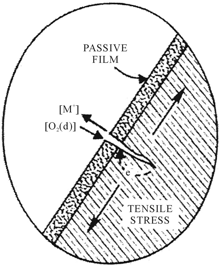
Figure 6. Stress corrosion mechanism.
of a small crack in the stent will cause stress concentrations. The cracks extend between grains, and this attack will initiate cracks that grow rapidly leading to failure.
Fatigue corrosion is a form of dynamic stress corrosion and is important since stents undergo cyclic mechanical deformations. Stents have a limit to cyclic loading, which may be reduced in the presence of corrosion in physical cracks or defects in a passive layer produced by single or repeated cyclic loading. The maximum stress that can be reached continuously decreases as the loading cycle number increases.
Although the presence of proteins and cells will not cause a new corrosion mechanism, they can influence the rate of corrosion by interfering with the anodic and cathodic reactions. There are four ways in which this can occur: 1) the biological molecule can upset the reaction equilibrium by consuming a product of anodic or cathodic reactions; e.g. proteins bind to metal ions and transport them away from the implant surface, 2) the stability of the oxide layer depends on the electrode potential and pH of the solution. Proteins and cells can be electrically active and interact with the charges formed at the interface and thus affect the electrode potential. Bacteria and inflammatory cells can alter the pH, 3) the stability of the oxide layer is also dependent on the availability of oxygen. Protein adsorption can affect the diffusion of oxygen to certain regions of the surface. This could cause preferential corrosion of the oxygen deficient regions leading to the breakdown of the passive layer, 4) the cathodic reaction results in the formation of hydrogen. The local build-up of hydrogen inhibits the cathodic reaction and restricts the corrosion process. In the vicinity of the implant, bacteria may utilize the hydrogen and play an important role in the corrosion process.
In conclusion, the study of corrosion is very complexand hence further work needs to be performed to improve alloy corrosion resistance of stents.
4.4. The Influence of Stent Design on Fracture
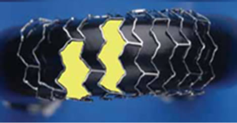
Stent design is complex because the design of ideal stent requires the following: ease of deliverability and trackability, a high expansion ratio, and the ability to reach tight lesions. The material itself has to be biocompatible, radiopaque, and resistant to corrosion. Although the current designs have been showing a great advancement, there is still no ideal stents. Each stents has its advantages and disadvantages that need to be customised to a specific clinical application. Therefore, it is possible that stent design (Figure 7) play a role in SF. Stents with a closed-cell design are more prone to fracture, compared to stents of open-cell design [78]. It has been suggested that the open-cell design is more “flexible” therefore, reducing the probability of stent fractures. However, other study does not support this hypothesis [79].
Another issue is the thickness of stent struts. It has been observed that a decreasing strut thickness (from 100 µm to about 65 µm) increases the radial strength of the stent, therefore improving the deliverability and life of the stent [23].
Stents must undergo stringent simulation tests before implantation, but vessel tortuosity, and rotational forces that a coronary stent has to withstand 70 times per minute for years are extremely difficult parameters to be incorporated in stent simulation tests [4].
5. Current Improvements
5.1. Improvements into the Design Aspects of Stents
There are significant numbers of developments towards achieving the ideal stent design. One of the problems with current stents is that they are of standard lengths. As mentioned above, the longer the stent, the more prone it is to fracture. Therefore, having a stent of a customized length would minimize this problem. Thus, one of the most innovative stent designs is the NX Co-Cr stent (Figure 8) designed by Xtent Custom [80]. The unique feature is that the stent consists of multiple 6 mm inter-digitating segments, which means the stent length is “infi-
 (a)
(a)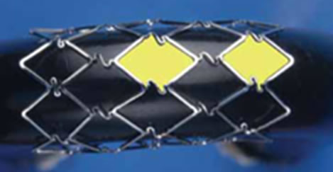 (b)
(b)
Figure 7. (a) Fully supported closed-cell design; (b) Opencell design [42].


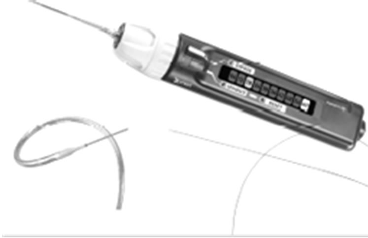
Figure 8. The interdigitating NX stent design by Xtent Custom [43]. Note that the manipulation of the switch on the handle (on-right) activates the separation of the inter-digitated segment at a desired location; therefore, the operator can customize the stent length.
nitely” variable, and hence, this system allows for inlesion determination of stent length instead of relying on fixed length stents [80]. Therefore, long or short lesions of variable lengths and diameters, can be treated with a single device [80]. Although this stent has been investigated in humans, further studies are in progress [80].
The TriMaxx stent is a novel way to achieve a thinner stent strut [23,81]. It is a stent with three layers in which tantalum (18 µm) is in between inner and outer layers of 316L stainless steel [23,81]; the total stent thickness is 74 µm which is less than other stents. The rationale behind the TriMaxx is not limited to the fact that tantalum has high ductility, excellent radiopacity and superior corrosion resistance but also offers a thin strut [23,81]. The safety and feasibility of the TriMaxx stent has been evaluated in 100 patients by analysing ISR after six months of deployment, and the result was 25% ISR [81], which is in the low range of ISR globally (typically 20 to 40%). Cross sectional and top views of TriMaxx stent is shown in Figure 9.
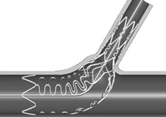
The Tryton Side-Branch Stent (Figure 10) is another unique design initiated by the Tryton Company [80]. They designed stents with side branch that fits completely in all bifurcation lesions with different angulations [80]. This stent is made of a cobalt-chromium alloy, and is composed of three different zones. These are a side branch region with a standard stent design, a transition zone, and the main vessel region [80]. A trial study was done on 30 patients, and shows a low major adverse
 (a)
(a)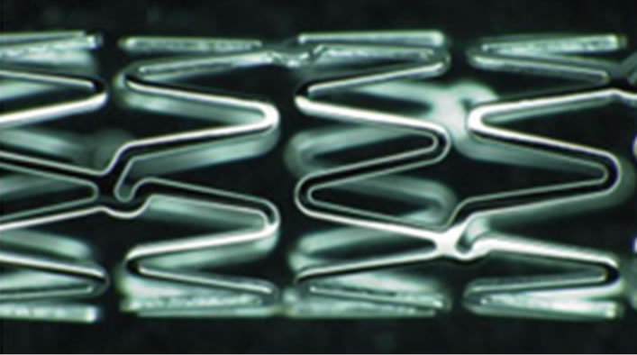 (b)
(b)
Figure 9. The triplex metal of the TriMaxx stent metal platform [44].
 (a)
(a) (b)
(b)
Figure 10. (a) The design of the Tryton side branch stent; (b) The Sideguard Ostium protection device [43].
cardiac events rate of 9.9% [80]. The result also shows a procedural success rate of 93.3% [80].
Side branch accessible main branch stents is another novel achievement proposed by TAXUS Petal. They are designed to preserve access to a side branch during a procedure and to ensure optimum scaffolding. It has a unique structure in the middle of the stent to provide consistent mechanical support to the side branch. This ostial preservation structure opens into the side branch ostium and adapts to the asymmetric anatomy of the side branch with variable angles. A side branch stabilizing wire allows direct side branch wiring and access after stent deployment into the parent vessel, and thus eliminates the need for stent strut re-crossing. The first human clinical trial of this stent is on-going.
5.2. Advanced Coatings for Improved Biocompatibility
Although no strong scientific evidence exists, it is believed that surface optimization could help in reducing restenosis rates for bare-metal stents below the typical range of 20% - 30% [82]. A wide variety of surface modifications and inorganic coatings were explored, targeting a range of goals such as stability of surface oxide-layer to reduce metal-ion release, reduced surface thrombogenicity, and surface texturing to promote endothelialization. Indeed, it is strongly believed that biomaterials with corrosion resistant oxide surfaces such as titanium oxide or chromium oxide improve biocompatibility by minimizing metal-ion release. While there had been many invitro studies of ion release from coronary stent, no clear clinical evidence was available with regard to the impact for patients. Koster et al. [35] found links between metal allergies and ISR. This study proposed that patients with sensitivity to nickel and molybdenum had a higher rate of ISR than patients without sensitivity. Therefore, the work did raise questions about the possible impact of metal-ion release from stainless steel, which is still the leading material in use for stents, even though the researchers reported limitations in their study. Indeed, the argument focused on nickel because it is present at higher levels than molybdenum in 316L stainless steel (nominally 12% vs. 2.5% respectively). Worthwhile to mention, metal ion release is not necessarily related to the elemental proportions in an alloy and is more influenced by stability and regeneration potential of the oxide. Although the developments of inorganic stent coatings are still on-going, to prevent ion-release, other study does not support the suggested relationship between nickel allergy and development of ISR in patients having stainless steel stents, and therefore large scale studies are needed to reach a final conclusion [83].
Carbon coatings [84] were explored earlier as another means of surface modification, with a number of different methods examined including “diamond-like carbon (DLC)” [85,86]. Gutensohn et al. [87] looked at the use of coronary stainless steel stents coated with a simple DLC (BioDiamond, Mainz, Germany). They found, from the in-vitro study, that this coating alone resulted in a significant decrease in both metal-ion release of nickel and chromium and also lower platelet activation in comparison to uncoated stents. On the other hand, results of the following studies did not support the previous researchers’ conclusion because it did not lead to improve biocompatibility. Airoldi et al. [88] compared bare stainless steel stent and DLC-coated stent in 347 patients. The six month follow-up showed no significant difference in restenosis rates between the two groups. Accordingly, although the DLC may reduce acute thrombosis, its value with respect to longer-term vessel patency was not evident. In addition, because some DLC-coated stents are both on the market and development stage, their ability to reduce metal ion release is probably still a marketable advantage over bare-metal stents. Another study by Hasebe et al. [89] investigated a fluorine-doped DLC, which had a higher ratio of albumin to fibrinogen adsorption and lower platelet adhesion and activation than non-doped DLC. They reported that the fluorine-doped DLC would significantly stop platelet adhesion and thrombus activation.
In summary, most inorganic coatings for stent have provided either ineffective or inconclusive results in terms of reducing restenosis, which was the primary goal behind their development. Although the above novel and well-engineered studies are not directly related to stents fracture, these developments will certainly enhance the function of stents including its mechanical integrity. Indeed, it will be significant players in the efforts to reduce restenosis rates, in their existing configurations, and this will help to increase the stent’s life.
6. Future Perspective
Since the early adoption of stent, it is believed that one of the key successes of stent performance is the ease with which it could be tracked through to the target vessel lesions. This feature is significantly affected by strut thickness; thinner struts lead to more flexible devices and reduced cross sectional profiles. It is also believed that thinner struts would lead to reduced restenosis rates and consequently enhance the stent fatigue life (i.e. less prone to fracture). Nowadays, most of the commercial stents have been manufactured from stainless steel 316L, because of its superior corrosion resistance and high ductility [24,25]. However, Co-Cr shows better corrosion resistance and higher density. Also, Co-Cr shows higher radial strength allowing for thinner stent struts which may reduce ISR, whilst reducing device profile and hence improving its deliverability to the target lesion [7, 22,23]. Indeed, the L605 alloy provided both increased strength and increased radiopacity in comparison to the stainless steel 316L, allowing for thinner struts without harming its radiopacity [49]. Therefore, there is a strong possibility that stent manufacturers will replace stainless steel 316L with Co-Cr alloys [22]. Unfortunately, there is a practical limit to which strut thickness can be successfully reduced. Stents manufactured from higher strength materials will have a tendency to increased elastic recoil, as it becomes more difficult to induce plastic deformation at equivalent device expansion strains. Besides, as strut thickness decreases and stent flexibility improves; a point is being reached where device trackability and crossing profile is becoming more dependent on the mechanical characteristics and dimensions of the balloon and delivery system than on the stent itself.
Since stents are subjected to cyclic stresses due to systolic and diastolic pressures generated by the heart in arteries (i.e. torsion, bending, tension, and compression), we can say that stent can be fractured due to fatigue mechanism. Therefore, the fatigue property of stent materials needs to be assessed and improved in order to confidently use the stents for longer life time. Fatigue characteristics are related mainly to microstructures, surface condition, heat treatment conditions, and the manufacturing process. AL-Mangour et al., have proposed a new technique to manufacture stents through cold spray [90,91]. Shot peening, which can describe the cold spray process, is a process in which metal spherical powders are shot at a component or a substrate [92]. This leads to a residual compressive stress at the surface of a component and this enhances fatigue life of materials. Indeed, cold spray uses micron-size particles that are accelerated to a high velocity (upto 1500 m/s) toward a suitable substrate using a supersonic gas jet [93-95]. This may help to solve the stent fracture problem, as a result of improvement in fatigue property.
7. Conclusions
• The following properties (enough elasticity and plasticity, low magnetic susceptibility, suitability for X-ray imaging, biocompatibility, suitable surface characteristics, and drug delivery capacity) are all necessary for the next generation of stents.
• Metals are used for stents due to its advantages over ceramics and polymers which include strength, toughness, high elasticity and plasticity. Bio-functionalizations through a combination of metals and polymers are subjects of further study.
• SF appears to be a clinically significant problem which is associated with short and possibly long-term morbidity rate. Clinically speaking, SF was observed in patients presenting with ISR, especially when the restenosis was focal. Most likely, SF was associated with overlapping stents, vessel angulation, stent structure, and stent diameter. This seconds the fact that further analysis of the biomechanical forces exerted on a coronary stent is required to understand so that means can be developed to avoid this significant clinical problem.
• The introduction of Co-Cr alloys in a new generation of stent has enabled a reduction in strut thickness, which has been shown as a positive factor for clinical performance. In addition, with a higher density and elastic modulus, Co-Cr appears of particular interest. Nevertheless, it was shown how tubing attributes influence stent performance and manufacturing, giving a basis for designers to properly specify the desired tubing parameters.
• Due to the increasing demand to treat more complex lesions with metallic stents, a number of novel stent designs have been developed. Most of the current innovative stents designs have shown promising results from clinical outcomes and feasibility studies. Indeed, larger randomized trials were performed or on-going to confirm the safety and efficiency of the devices further. The next generation technologies will expand the field of intracoronary stenting and improve clinical outcomes for patients with coronary artery disease.
8. Acknowledgements
The Saudi Basic Industries Corporation (SABIC), Saudi Arabia, is thankful for generously affording a financial support to one of the authors, Bandar AL-Mangour.
REFERENCES
- C. D. Mathers, T. Boerma and D. Ma Fat, “Global and Regional Causes of Death,” British Medical Bulletin, Vol. 92, No. 1, 2009, pp. 7-32. http://dx.doi.org/10.1093/bmb/ldp028
- S. Garg and P. W. Serruys, “Coronary Stents: Current Status,” Journal of the American College of Cardiology, Vol. 56, No. 10, 2010, pp. S1-S42. http://dx.doi.org/10.1016/j.jacc.2010.06.007
- S. Yusuf, D. Zucker, E. Passamani, P. Peduzzi, T. Takaro, L. D. Fisher, et al., “Effect of Coronary Artery Bypass Graft Surgery on Survival: Overview of 10-Year Results from Randomised Trials by the Coronary Artery Bypass Graft Surgery Trialists Collaboration,” The Lancet, Vol. 344, No. 8922, 1994, pp. 563-570. http://dx.doi.org/10.1016/S0140-6736(94)91963-1
- F. Shaikh, R. Maddikunta, M. Djelmami-Hani, J. Solis, S. Allaqaband and T. Bajwa, “Stent Fracture, an Incidental Finding or a Significant Marker of Clinical In-Stent Restenosis?” Catheterization and Cardiovascular Interventions, Vol. 71, No. 5, 2008, pp. 614-618. http://dx.doi.org/10.1002/ccd.21371
- M. Nakatani, Y. Takeyama, M. Shibata, M. Yorozuya, H. Suzuki, S. Koba, et al., “Mechanisms of Restenosis after Coronary Intervention: Difference between Plain Old Balloon Angioplasty and Stenting,” Cardiovascular Pathology, Vol. 12, No. 1, 2003, pp. 40-48. http://dx.doi.org/10.1016/S1054-8807(02)00135-7
- N. Kukreja, Y. Onuma, J. Daemen and P. W. Serruys, “The Future of Drug-Eluting Stents,” Pharmacological Research, Vol. 57, No. 3, 2008, pp. 171-180. http://dx.doi.org/10.1016/j.phrs.2008.01.012
- D. R. Whittaker and M. F. Fillinger, “The Engineering of Endovascular Stent Technology: A Review,” Vascular and Endovascular Surgery, Vol. 40, No. 2, 2006, pp. 85- 94. http://dx.doi.org/10.1177/153857440604000201
- Y. P. Kathuria, “The Potential of Biocompatible Metallic Stents and Preventing Restenosis,” Materials Science and Engineering: A, Vol. 417, No. 1-2, 2006, pp. 40-48. http://dx.doi.org/10.1016/j.msea.2005.11.007
- G. Maluenda, G. Lemesle and R. Waksman, “A Critical Appraisal of the Safety and Efficacy of Drug-Eluting Stents,” Clinical Pharmacology and Therapeutics, Vol. 85, No. 5, 2009, pp. 474-480. http://dx.doi.org/10.1038/clpt.2009.8
- G. Nakazawa, A. V. Finn, M. Vorpahl, E. Ladich, R. Kutys, I. Balazs, et al., “Incidence and Predictors of Drug-Eluting Stent Fracture in Human Coronary Artery: A Pathologic Analysis,” Journal of the American College of Cardiology, Vol. 54, No. 21, 2009, pp. 1924-1931. http://dx.doi.org/10.1016/j.jacc.2009.05.075
- P. S. Chowdhury and R. G. Ramos, “Coronary-Stent Fracture,” New England Journal of Medicine, Vol. 347, No. 8, 2002, p. 581. http://dx.doi.org/10.1056/NEJMicm020259
- M. Carrozza, G. Santoro, M. G. Russo, G. Caianiello and R. Calabrò, “Stress Stent Fracture: Is Stent Angioplasty Really a Safe Therapeutic Option in Native Aortic Coarctation?” International Journal of Cardiology, Vol. 113, No. 1, 2006, pp. 127-128.
- R. V. Marrey, R. Burgermeister, R. B. Grishaber and R. O. Ritchie, “Fatigue and Life Prediction for CobaltChromium Stents: A Fracture Mechanics Analysis,” Biomaterials, Vol. 27, No. 9, 2006, pp. 1988-2000. http://dx.doi.org/10.1016/j.biomaterials.2005.10.012
- S.-H. Lee, J.-S. Park, D.-G. Shin, Y.-J. Kim, G.-R. Hong, W. Kim, et al., “Frequency of Stent Fracture as a Cause of Coronary Restenosis after Sirolimus-Eluting Stent Implantation,” The American Journal of Cardiology, Vol. 100, No. 4, 2007, pp. 627-630. http://dx.doi.org/10.1016/j.amjcard.2007.03.073
- G. Sianos, S. Hofma, J. M. R. Ligthart, F. Saia, A. Hoye, P. A. Lemos, et al., “Stent Fracture and Restenosis in the Drug-Eluting Stent Era,” Catheterization and Cardiovascular Interventions, Vol. 61, No. 1, 2004, pp. 111-116. http://dx.doi.org/10.1002/ccd.10709
- H.-S. Kim, Y.-H. Kim, S.-W. Lee, D.-W. Park, C. W. Lee, M.-K. Hong, et al., “Incidence and Predictors of DrugEluting Stent Fractures in Long Coronary Disease,” International Journal of Cardiology, Vol. 133, No. 3, 2009, pp. 354-358. http://dx.doi.org/10.1016/j.ijcard.2008.01.005
- J. Aoki, G. Nakazawa, K. Tanabe, A. Hoye, H. Yamamoto, T. Nakayama, et al., “Incidence and Clinical Impact of Coronary Stent Fracture after Sirolimus-Eluting Stent Implantation,” Catheterization and Cardiovascular Interventions, Vol. 69, No. 3, 2007, pp. 380-386. http://dx.doi.org/10.1002/ccd.20950
- M. S. Lee, D. Jurewitz, J. Aragon, J. Forrester, R. R. Makkar and S. Kar, “Stent Fracture Associated with Drug-Eluting Stents: Clinical Characteristics and Implications,” Catheterization and Cardiovascular Interventions, Vol. 69, No. 3, 2007, pp. 387-394. http://dx.doi.org/10.1002/ccd.20942
- T. Sharkawi, F. Cornhill, A. Lafont, P. Sabaria and M. Vert, “Intravascular Bioresorbable Polymeric Stents: A Potential Alternative to Current Drug Eluting Metal Stents,” Journal of Pharmaceutical Sciences, Vol. 96, No. 11, 2007, pp. 2829-2837. http://dx.doi.org/10.1002/jps.20957
- A. Al-Aown, I. Kyriazis, P. Kallidonis, P. Kraniotis, C. Rigopoulos, D. Karnabatidis, et al., “Ureteral Stents: New Ideas, New Designs,” Therapeutic Advances in Urology, Vol. 2, No. 2, 2010, pp. 85-92. http://dx.doi.org/10.1177/1756287210370699
- P. Poncin and J. Proft, “Stent Tubing: Understanding the Desired Attributes,” Materials & Process for Medical Devices Conference, Anaheim, 8-10 September 2003, 7p.
- P. Poncin, C. Millet, J. Chevry and J. L. Proft, “Comparing and Optimizing Co-Cr Tubing Properties for Stent Applications,” Materials & Process for Medical Devices Conference, St. Paul, 25-27 August 2004, 6p.
- B. O’Brien and W. Carroll, “The Evolution of Cardiovascular Stent Materials and Surfaces in Response to Clinical Drivers: A Review,” Acta Biomaterialia, Vol. 5, No. 4, 2009, pp. 945-958. http://dx.doi.org/10.1016/j.actbio.2008.11.012
- G. Mani, M. D. Feldman, D. Patel and C. M. Agrawal, “Coronary Stents: A Materials Perspective,” Biomaterials, Vol. 28, No. 9, 2007, pp. 1689-1710. http://dx.doi.org/10.1016/j.biomaterials.2006.11.042
- T. Hanawa, “Materials for Metallic Stents,” Journal of Artificial Organs, Vol. 12, No. 2, 2009, pp. 73-79. http://dx.doi.org/10.1007/s10047-008-0456-x
- M. Niinomi, “Fatigue Characteristics of Metallic Biomaterials,” International Journal of Fatigue, Vol. 29, No. 6, 2007, pp. 992-1000. http://dx.doi.org/10.1016/j.ijfatigue.2006.09.021
- R. A. Lula, “Stainless Steel,” American Society for Metals, Russell Township, 1985.
- A. J. Sedriks, “Corrosion of Stainless Steel,” 2nd Edition, John Wiley & Sons, Hoboken, 1996.
- H. K. Mardis and R. M. Kroeger, “Ureteral Stents. Materials,” The Urologic Clinics of North America, Vol. 15, No. 3, 1988, pp. 471-479.
- A. Raval, A. Choubey, C. Engineer and D. Kothwala, “Development and Assessment of 316LVM Cardiovascular Stents,” Materials Science and Engineering: A, Vol. 386, No. 1-2, 2004, pp. 331-343.
- A. Holton, E. Walsh, A. Anayiotos, G. Pohost and R. Venugopalan, “Comparative MRI Compatibility of 316L Stainless Steel Alloy and Nickel-Titanium Alloy Stents,” Journal of Cardiovascular Magnetic Resonance, Vol. 4, No. 4, 2002, pp. 423-430. http://dx.doi.org/10.1081/JCMR-120016381
- G. T. Burstein, P. C. Pistorius and S. P. Mattin, “The Nucleation and Growth of Corrosion Pits on Stainless Steel,” Corrosion Science, Vol. 35, No. 1-4, 1993, pp. 57- 62. http://dx.doi.org/10.1016/0010-938X(93)90133-2
- C.-C. Shih, C.-M. Shih, Y.-Y. Su, L. H. J. Su, M.-S. Chang and S.-J. Lin, “Effect of Surface Oxide Properties on Corrosion Resistance of 316L Stainless Steel for Biomedical Applications,” Corrosion Science, Vol. 46, No. 2, 2004, pp. 427-441. http://dx.doi.org/10.1016/S0010-938X(03)00148-3
- C. L. Liu, P. K. Chu, G. Q. Lin and M. Qi, “Anti-Corrosion Characteristics of Nitride-Coated AISI 316L Stainless Steel Coronary Stents,” Surface and Coatings Technology, Vol. 201, No. 6, 2006, pp. 2802-2806. http://dx.doi.org/10.1016/j.surfcoat.2006.05.028
- R. Köster, D. Vieluf, M. Kiehn, M. Sommerauer, J. Kähler, S. Baldus, et al., “Nickel and Molybdenum Contact Allergies in Patients with Coronary In-Stent Restenosis,” The Lancet, Vol. 356, No. 9245, 2000, pp. 1895- 1897. http://dx.doi.org/10.1016/S0140-6736(00)03262-1
- Y. Okazaki and E. Gotoh, “Metal Release from Stainless Steel, Co-Cr-Mo-Ni-Fe and Ni-Ti Alloys in Vascular Implants,” Corrosion Science, Vol. 50, No. 12, 2008, pp. 3429-3438. http://dx.doi.org/10.1016/j.corsci.2008.09.002
- M. Assad, N. Lemieux, C. H. Rivard and L. H. Yahia, “Comparative in Vitro Biocompatibility of Nickel-Titanium, Pure Nickel, Pure Titanium, and Stainless Steel: Genotoxicity and Atomic Absorption Evaluation,” BioMedical Materials and Engineering, Vol. 9, No. 1, 1999, pp. 1-12.
- K. Otsuka and X. Ren, “Physical Metallurgy of Ti-NiBased Shape Memory Alloys,” Progress in Materials Science, Vol. 50, No. 5, 2005, pp. 511-678. http://dx.doi.org/10.1016/j.pmatsci.2004.10.001
- J. M. McNaney, V. Imbeni, Y. Jung, P. Papadopoulos and R. O. Ritchie, “An Experimental Study of the Superelastic Effect in a Shape-Memory Nitinol Alloy under Biaxial Loading,” Mechanics of Materials, Vol. 35, No. 10, 2003, pp. 969-986. http://dx.doi.org/10.1016/S0167-6636(02)00310-1
- A. L. McKelvey and R. O. Ritchie, “Fatigue-Crack Propagation in Nitinol, a Shape-Memory and Superelastic Endovascular Stent Material,” Journal of Biomedical Materials Research, Vol. 47, No. 3, 1999, pp. 301-308. http://dx.doi.org/10.1002/(SICI)1097-4636(19991205)47:3<301::AID-JBM3>3.0.CO;2-H
- J. M. Stankiewicz, S. W. Robertson and R. O. Ritchie, “Fatigue-Crack Growth Properties of Thin-Walled Superelastic Austenitic Nitinol Tube for Endovascular Stents,” Journal of Biomedical Materials Research Part A, Vol. 81A, No. 3, 2007, pp. 685-691. http://dx.doi.org/10.1002/jbm.a.31100
- K. Gall, J. Tyber, G. Wilkesanders, S. W. Robertson, R. O. Ritchie and H. J. Maier, “Effect of Microstructure on the Fatigue of Hot-Rolled and Cold-Drawn NiTi Shape Memory Alloys,” Materials Science and Engineering: A, Vol. 486, No. 1-2, 2008, pp. 389-403. http://dx.doi.org/10.1016/j.msea.2007.11.033
- D. Stoeckel, A. Pelton and T. Duerig, “Self-Expanding Nitinol Stents: Material and Design Considerations,” European Radiology, Vol. 14, No. 2, 2004, pp. 292-301. http://dx.doi.org/10.1007/s00330-003-2022-5
- C.-C. Shih, S.-J. Lin, Y.-L. Chen, Y.-Y. Su, S.-T. Lai, G. J. Wu, et al., “The Cytotoxicity of Corrosion Products of Nitinol Stent Wire on Cultured Smooth Muscle Cells,” Journal of Biomedical Materials Research, Vol. 52, No. 2, 2000, pp. 395-403. http://dx.doi.org/10.1002/1097-4636(200011)52:2<395::AID-JBM21>3.0.CO;2-B
- S. A. Shabalovskaya, “Surface, Corrosion and Biocompatibility Aspects of Nitinol as an Implant Material,” Bio-Medical Materials and Engineering, Vol. 12, No. 1, 2002, pp. 69-109.
- T. Duerig, A. Pelton and D. Stöckel, “An Overview of Nitinol Medical Applications,” Materials Science and Engineering: A, Vol. 273-275, 1999, pp. 149-160. http://dx.doi.org/10.1016/S0921-5093(99)00294-4
- B. Thierry, Y. Merhi, L. Bilodeau, C. Trépanier and M. Tabrizian, “Nitinol versus Stainless Steel Stents: Acute Thrombogenicity Study in an ex Vivo Porcine Model,” Biomaterials, Vol. 23, No. 14, 2002, pp. 2997-3005. http://dx.doi.org/10.1016/S0142-9612(02)00030-3
- US Food and Drug Administration CfDaRH, “Multi-Link Visiontm RX & OTW Coronary Stent System-P020047,” 2003. www.fda.gov/
- D. J. Kereiakes, D. A. Cox, J. B. Hermiller, M. G. Midei, W. B. Bachinsky, E. D. Nukta, et al., “Usefulness of a Cobalt Chromium Coronary Stent Alloy,” American Journal of Cardiology, Vol. 92, No. 4, 2003, pp. 463-466. http://dx.doi.org/10.1016/S0002-9149(03)00669-6
- M. Niinomi, “Recent Metallic Materials for Biomedical Applications,” Metallurgical and Materials Transactions A, Vol. 33, No. 3, 2002, pp. 477-486. http://dx.doi.org/10.1007/s11661-002-0109-2
- B. J. O’Brien, J. S. Stinson, S. R. Larsen, M. J. Eppihimer and W. M. Carroll, “A Platinum-Chromium Steel for Cardiovascular Stents,” Biomaterials, Vol. 31, No. 14, 2010, pp. 3755-3761. http://dx.doi.org/10.1016/j.biomaterials.2010.01.146
- Z. M. Hijazi, M. Homoud, M. J. Aronovitz, J. J. Smith and G. T. Faller, “A New Platinum Balloon-Expandable stent (Angiostent) Mounted on a High Pressure Balloon: Acute and Late Results in an Atherogenic Swine Model,” The Journal of Invasive Cardiology, Vol. 7, No. 5, 1995, pp. 127-134.
- B. Bhargava, I. De Scheerder, Q. B. Ping, H. Yanming, R. Chan, H. Soo Kim, et al., “A Novel Platinum-Iridium, Potentially Gamma Radioactive Stent: Evaluation in a Porcine Model,” Catheterization and Cardiovascular Interventions, Vol. 51, No. 3, 2000, pp. 364-368. http://dx.doi.org/10.1002/1522-726X(200011)51:3<364::AID-CCD28>3.0.CO;2-D
- D. W. Trost, H. L. Zhang, M. R. Prince, P. A. Winchester, Y. Wang, R. Watts, et al., “Three-Dimensional MR Angiography in Imaging Platinum Alloy Stents,” Journal of Magnetic Resonance Imaging, Vol. 20, No. 6, 2004, pp. 975-980. http://dx.doi.org/10.1002/jmri.20209
- J. B. Park, “Metallic Implant Materials,” Plenum Press, New York, 1987.
- R. Foti, C. Tamburino, A. R. Galassi, G. Russo, A. Nicosia, R. Grassi, et al., “Safety, Feasibility and Efficacy of a New Single-Wire Stent in the Treatment of Complex Coronary Lesions: The Angiostent,” Cardiologia, Vol. 43, No. 7, 1998, pp. 725-730.
- P. F. Johnson, J. J. Bernstein, G. Hunter, W. W. Dawson and L. L. Hench, “An in Vitro and in Vivo Analysis of Anodized Tantalum Capacitive Electrodes: Corrosion Response, Physiology, and Histology,” Journal of Biomedical Materials Research, Vol. 11, No. 5, 1977, pp. 637-656. http://dx.doi.org/10.1002/jbm.820110502
- K. H. Barth, R. Virmani, J. Froelich, T. Takeda, S. V. Lossef, J. Newsome, et al., “Paired Comparison of Vascular Wall Reactions to Palmaz Stents, Strecker Tantalum Stents, and Wallstents in Canine Iliac and Femoral Arteries,” Circulation, Vol. 93, No. 12, 1996, pp. 2161-2169. http://dx.doi.org/10.1161/01.CIR.93.12.2161
- G. Teitelbaum, M. Raney, M. Carvlin, A. Matsumoto and K. Barth, “Evaluation of Ferromagnetism and Magnetic Resonance Imaging Artifacts of the Strecker Tantalum Vascular Stent,” CardioVascular and Interventional Radiology, Vol. 12, No. 3, 1989, pp. 125-127. http://dx.doi.org/10.1007/BF02577374
- S. V. Lossef, R. J. Lutz, J. Mundorf and K. H. Barth, “Comparison of Mechanical Deformation Properties of Metallic Stents with Use of Stress-Strain Analysis,” Journal of Vascular and Interventional Radiology, Vol. 5, No. 2, 1994, pp. 341-349. http://dx.doi.org/10.1016/S1051-0443(94)71499-8
- J. Dyet, W. Watts, D. Ettles and A. Nicholson, “Mechanical Properties of Metallic Stents: How Do These Properties Influence the Choice of Stent for Specific Lesions? CardioVascular and Interventional Radiology, Vol. 23, No. 1, 2000, pp. 47-54. http://dx.doi.org/10.1007/s002709910007
- J. E. Sousa, P. W. Serruys and M. A. Costa, “New Frontiers in Cardiology: Drug-Eluting Stents: Part I,” Circulation, Vol. 107, No. 17, 2003, pp. 2274-2279. http://dx.doi.org/10.1161/01.CIR.0000069330.41022.90
- M. Moravej and D. Mantovani, “Biodegradable Metals for Cardiovascular Stent Application: Interests and New Opportunities,” International Journal of Molecular Sciences, Vol. 12, No. 7, 2011, pp. 4250-4270. http://dx.doi.org/10.3390/ijms12074250
- F.-T. Chung, S.-M. Lin, H.-C. Chen, C.-L. Chou, C.-T. Yu, C.-Y. Liu, et al., “Factors Leading to Tracheobronchial Self-Expandable Metallic Stent Fracture,” The Journal of Thoracic and Cardiovascular Surgery, Vol. 136, No. 5, 2008, pp. 1328-1335. http://dx.doi.org/10.1016/j.jtcvs.2008.05.039
- K. J. Miller, “Materials Science Perspective of Metal Fatigue Resistance,” Materials Science and Technology, Vol. 9, No. 6, 1993, pp. 453-462. http://dx.doi.org/10.1179/026708393790172178
- B. P. Murphy, P. Savage, P. E. McHugh and D. F. Quinn, “The Stress-Strain Behavior of Coronary Stent Struts Is Size Dependent,” Annals of Biomedical Engineering, Vol. 31, No. 6, 2003, pp. 686-691. http://dx.doi.org/10.1114/1.1569268
- B. Murphy, H. Cuddy, F. Harewood, T. Connolley and P. McHugh, “The Influence of Grain Size on the Ductility of Micro-Scale Stainless Steel Stent Struts,” Journal of Materials Science: Materials in Medicine, Vol. 17, No. 1, 2006, pp. 1-6. http://dx.doi.org/10.1007/s10856-006-6323-5
- F. Etave, G. Finet, M. Boivin, J.-C. Boyer, G. Rioufol and G. Thollet, “Mechanical Properties of Coronary Stents Determined by Using Finite Element Analysis,” Journal of Biomechanics, Vol. 34, No. 8, 2001, pp. 1065-1075. http://dx.doi.org/10.1016/S0021-9290(01)00026-4
- J. R. Davis, “Handbook of Materials for Medical Devices,” ASM International, Russell Township, 2003.
- K. Takahata, Y. B. Gianchandani, “A Planar Approach for Manufacturing Cardiac Stents: Design, Fabrication, and Mechanical Evaluation,” Microelectromechanical Systems, Vol. 13, No. 6, 2004, pp. 933-939. http://dx.doi.org/10.1109/JMEMS.2004.838357
- A. Schuessler, “Manufacturing of Stents: Optimize the Stent with New Manufacturing Technology,” 2007.
- Y. P. Kathuria, “The Potential of Biocompatible Metallic Stents and Preventing Restenosis,” Materials Science and Engineering: A, Vol. 417, No. 1-2, 2006, pp. 40-48. http://dx.doi.org/10.1016/j.msea.2005.11.007
- D. Scheinert, S. Scheinert, J. Sax, C. Piorkowski, S. Bräunlich, M. Ulrich, et al., “Prevalence and Clinical Impact of Stent Fractures after Femoropopliteal Stenting,” Journal of the American College of Cardiology, Vol. 45, No. 2, 2005, pp. 312-315. http://dx.doi.org/10.1016/j.jacc.2004.11.026
- A. Halkin, S. Carlier and M. B. Leon, “Late Incomplete Lesion Coverage Following Cypher Stent Deployment for Diffuse Right Coronary Artery Stenosis,” Heart, Vol. 90, No. 8, 2004, p. e45. http://dx.doi.org/10.1136/hrt.2004.034538
- P.-K. Min, Y.-W. Yoon and H. Moon Kwon, “Delayed Strut Fracture of Sirolimus-Eluting Stent: A Significant Problem or an Occasional Observation?” International Journal of Cardiology, Vol. 106, No. 3, 2006, pp. 404- 406. http://dx.doi.org/10.1016/j.ijcard.2004.12.087
- C. Heintz, G. Riepe, L. Birken, E. Kaiser, N. Chakfé, M. Morlock, et al., “Corroded Nitinol Wires in Explanted Aortic Endografts: An Important Mechanism of Failure?” Journal of Endovascular Therapy, Vol. 8, No. 3, 2001, pp. 248-253. http://dx.doi.org/10.1583/1545-1550(2001)008<0248:CNWIEA>2.0.CO;2
- C.-C. Shih, S.-J. Lin, K.-H Chung, Y.-L Chen and Y.-Y. Su, “Increased Corrosion Resistance of Stent Materials by Converting Current Surface Film of Polycrystalline Oxide into Amorphous Oxide,” Journal of Biomedical Materials Research, Vol. 52, No. 2, 2000, pp. 323-332. http://dx.doi.org/10.1002/1097-4636(200011)52:2<323::AID-JBM11>3.0.CO;2-Z
- M. H. Wholey, “Designing the Ideal Stent,” Endovascular Today, Vol. 6, 2007, pp. 25-34.
- M. Schillinger, M. Gschwendtner, B. Reimers, J. Trenkler, L. Stockx, J. Mair, et al., “Does Carotid Stent Cell Design Matter?” Stroke, Vol. 39, No. 3, 2008, pp. 905-909. http://dx.doi.org/10.1161/STROKEAHA.107.499145
- B.-K. Koo and P. J. Fitzgerald, “Novel Coronary Stent Platforms,” Korean Circulation Journal, Vol. 38, No. 8, 2008, pp. 393-397. http://dx.doi.org/10.4070/kcj.2008.38.8.393
- A. Abizaid, J. J. Popma, L. F. Tanajura, K. Hattori, B. Solberg, C. Larracas, et al., “Clinical and Angiographic Results of Percutaneous Coronary Revascularization Using a Trilayer Stainless Steel-Tantalum-Stainless Steel Phosphorylcholine-Coated Stent: The TriMaxx Trial,” Catheterization and Cardiovascular Interventions, Vol. 70, No. 7, 2007, pp. 914-919. http://dx.doi.org/10.1002/ccd.21279
- G. Sydow-Plum and M. Tabrizian, “Review of Stent Coating Strategies: Clinical Insights,” Materials Science and Technology, Vol. 24, No. 9, 2008, pp. 1127-1143. http://dx.doi.org/10.1179/174328408X341816
- T. Norgaz, G. Hobikoglu, Z. A. Serdar, H. Aksu, A. T. Alper, O. Ozer, et al., “Is There a Link between Nickel Allergy and Coronary Stent Restenosis?” The Tohoku Journal of Experimental Medicine, Vol. 206, No. 3, 2005, pp. 243-246. http://dx.doi.org/10.1620/tjem.206.243
- A. Grill, “Diamond-Like Carbon Coatings as Biocompatible Materials—An Overview,” Diamond and Related Materials, Vol. 12, No. 2, 2003, pp. 166-170. http://dx.doi.org/10.1016/S0925-9635(03)00018-9
- R. Hauert, “A Review of Modified DLC Coatings for Biological Applications,” Diamond and Related Materials, Vol. 12, No. 3-7, 2003, pp. 583-589. http://dx.doi.org/10.1016/S0925-9635(03)00081-5
- R. K. Roy and K.-R. Lee, “Biomedical Applications of Diamond-Like Carbon Coatings: A Review,” Journal of Biomedical Materials Research Part B: Applied Biomaterials, Vol. 83B, No. 1, 2007, pp. 72-84. http://dx.doi.org/10.1002/jbm.b.30768
- K. Gutensohn, C. Beythien, J. Bau, T. Fenner, P. Grewe, R. Koester, et al., “In Vitro Analyses of Diamond-Like Carbon Coated Stents: Reduction of Metal Ion Release, Platelet Activation, and Thrombogenicity,” Thrombosis Research, Vol. 99, No. 6, 2000, pp. 577-585. http://dx.doi.org/10.1016/S0049-3848(00)00295-4
- F. Airoldi, A. Colombo, D. Tavano, G. Stankovic, S. Klugmann, V. Paolillo, et al., “Comparison of DiamondLike Carbon-Coated Stents versus Uncoated Stainless Steel Stents in Coronary Artery Disease,” The American Journal of Cardiology, Vol. 93, No. 4, 2004, pp. 474-477. http://dx.doi.org/10.1016/j.amjcard.2003.10.048
- T. Hasebe, S. Yohena, A. Kamijo, Y. Okazaki, A. Hotta, K. Takahashi, et al., “Fluorine Doping into DiamondLike Carbon Coatings Inhibits Protein Adsorption and Platelet Activation,” Journal of Biomedical Materials Research Part A, Vol. 83A, No. 4, 2007, pp. 1192-1199. http://dx.doi.org/10.1002/jbm.a.31340
- B. Al-Mangour, R. Dallala, F. Zhim, R. Mongrain and S. Yue, “Fatigue Behavior of Annealed Cold-Sprayed 316L Stainless Steel Coating for Biomedical Applications,” Materials Letters, Vol. 91, 2013, pp. 352-355. http://dx.doi.org/10.1016/j.matlet.2012.10.030
- B. Al-Mangour, R. Mongrain, E. Irissou and S. Yue, “Improving the Strength and Corrosion Resistance of 316L Stainless Steel for Biomedical Applications Using Cold Spray,” Surface and Coatings Technology, Vol. 216, 2013, pp. 297-307.
- S. Bagheri and M. Guagliano, “Review of Shot Peening Processes to Obtain Nanocrystalline Surfaces in Metal Alloys,” Surface Engineering, Vol. 25, No. 1, 2009, pp. 3-14. http://dx.doi.org/10.1179/026708408X334087
- F. Gärtner, T. Stoltenhoff, T. Schmidt and H. Kreye, “The Cold Spray Process and Its Potential for Industrial Applications,” Journal of Thermal Spray Technology, Vol. 15, No. 2, 2006, pp. 223-232. http://dx.doi.org/10.1361/105996306X108110
- R. Ghelichi, “Coating by the Cold Spray Process: A State of the Art,” Frattura ed Integrità Strutturale, Vol. 8, No. 8, 2009, pp. 30-44.
- E. Irissou, J.-G. Legoux, A. Ryabinin, B. Jodoin and C. Moreau, “Review on Cold Spray Process and Technology: Part I—Intellectual Property,” Journal of Thermal Spray Technology, Vol. 17, No. 4, 2008, pp. 495-516. http://dx.doi.org/10.1007/s11666-008-9203-3
NOTES
*Corresponding author.