Materials Sciences and Applications
Vol.4 No.3(2013), Article ID:29550,7 pages DOI:10.4236/msa.2013.43024
The Influence of Welding Parameters on Brittle Fracture of Liquefied Natural Gas Storage Tank Welded Joint
![]()
Production Engineering and Mechanical Design Department, Faculty of Engineering, Tanta University, Tanta, Egypt.
Email: engmghanem66@yahoo.com
Received December 9th, 2012; revised January 11th, 2013; accepted February 9th, 2013
Keywords: 9% Ni Steel Plate; LNG Tank; Heat Input; Mechanical Properties; Welding Process and Brittle Fracture
ABSTRACT
Many applications operate at sufficiently low temperature conditions where most structural steels become very brittle and, therefore, unsuitable for use in safety-critical structures. So the materials used in the vessels or storage tanks which keep the natural gas at liquefaction temperatures need to remain ductile and crack resistant with a high level of safety. The material also needs to have high strength in order to reduce the wall thickness of the container and it must permit welding without any risk of brittle fracture. 9% Ni steel plates are one of most common used materials in the LNG storage tank application. However, the welding procedure for 9% Ni steel plates requires high level of skills of welding that is strictly controlled welding parameter for balancing avoidance of cold and hot cracking and maintenance of high strength. Mechanical properties are important characteristics of the weldment that must confirm to the application feasibility as well as functional requirements of the welded joint. The only way to enhanced the mechanical properties of welded joint by controlling the parameters of using welding process. From the main variables of the arc welding process are the heat input and interpass temperature where the two variables control the thermal cycle of welding process. The experiment show that for thin test specimen with thickness ≤ 14 mm, the heat input range from 1.4 to 2 KJ/mm and controlling interpass temperature within 80˚C give high tensile strength with improving the toughness properties of welded joint and reduce the probability of brittle fracture happened by increase the ductility and reduce the yield strength and increased the transition temperature.
1. Introduction
Metallurgical characteristics of the weld metal as well as heat affected zone (HAZ) are very important because this directly influence the weld mechanical properties and joint performances. It is well known that the micro structure of the weld metal is different from the microstructure of base metal as well as HAZ. The weld microstructures, however, are somewhat different with respect to distributions of martensite and austenite, their amounts, grain sizes etc. depending upon the welding conditions adopted. From more important application is (LNG) that will be liquefy at −163˚C and is therefore stored or transported around −170˚C. At this low temperature quenched and tempered 9% nickel steels have the fracture toughness and crack arrest properties required for safe construction of tanks and vessels [1].
Combination of high strength and good toughness is essential for the steels used in liquefied natural gas epically there is a high risk assessment of probability of leakage done. The excellent low temperature notch impact properties of 9% nickel steels arise from the fine grained structure of tough nickel-ferrite free from embrittling carbide networks. The optimum microstructure and mechanical properties are obtained by a carefully controlled heat-treatment in the production of the steel [2].
These unique properties of the 9% Ni steel plates have resulted from the microstructure where consist mainly from fine martensite and from 5% - 15% retained austenite. This microstructure is existing due to quenching and tempering [3-5].
The welding is widely used in construction these applications, controlling the parameters which affect the weldability of 9% Ni steels is critical to the successful implementation of these engineering materials [6].
The weldability of 9% nickel steel is excellent and the steel is not susceptible to cracking and shows little or no detoriation of the properties by the heat inputs normally used during the welding with procedures. Heat input should not exceed 3 kJ/mm and interpass temperature must be limited to max 100˚C - 150˚C [1,2].
The strength and toughness required for the weld metal differs greatly depending upon the application for which the structure is employed and according to the type of steel and welding materials. Depending upon the welding processes the thermal conditions differ greatly up to the time when the weld metal is formed, solidifies and is cooled. The properties will differ according to the difference in welding conditions and especial without the postweld heat treatment (PWHT) even when identical welding processes and welding materials are employed. [7].
Both strength and toughness are critical properties since failure may occur through either ductile rupture or fracture. The combination is important since strength and toughness have an inverse relation to one another; an increase in strength at given temperature almost invariably leads to a decrease in fracture toughness. While there is no reliable quantitative theory of the strength—toughness relation of structural alloys [8].
For such inhomogeneous systems, measurement of the toughness alone has little meaning if it is not related to the tensile properties of the material system. It has been demonstrated that the apparent fracture toughness of the same HAZ microstructure can be changed dramatically by just changing the tensile properties in the adjacent weld metal [9].
The cooling rate is a primary factor that determines the final metallurgical structure of the weld and heat affected zone (HAZ), and is especially important with heattreated steels. Especially during welding quenched and tempered steels, the slow cooling rates (resulting from high heat inputs) can soften the material adjacent to the weld, reducing the load-carrying capacity of the connection [10].
Weldment toughness tends to deteriorate with increase in welding heat input. It is said that this tendency is caused by the austenite grain growth at the heat-affected zone (HAZ) during the welding thermal cycle [11,12].
Although With the increase of heat input, the impact toughness of weld zone and heat affected zone decrease, whereas the tensile strength of the weld joints does not change at all [13].
Under different weld heat inputs, the impact energy of the HAZ has a larger difference, indicating a tendency for a change in the fine structure of the HAZ. By controlling weld heat input = 20 kJ/cm, the presence of carbide in the HAZ can be removed, and therefore the impact toughness in this zone can be assured [10,11].
A specific maximum interpass temperature in welding procedure is sometimes required e.g., in order to avoid hot cracking. In this case using a higher interpass temperature will increase the time spent in the critical temperature range [14,15].
This is also an issue with high strength steel weld metals but using a high interpass temperature normally plays a more important role. Longer cooling times allows hydrogen diffusion from the weld and is a major factor when avoiding hydrogen cracking [16].
As interpass temperature is increased, the main microstructural effect is that the amount of columnar structure within a reheated weld bead is reduced and an increase in the amount of re-austerities and tempered areas is seen especially within the central beads of a welded joint. Little effects are seen on the cross sectional area of each weld bead deposited with increase in interpass temperature but the proportion of recrystallised area increases [17]. By eliminating the columnar microstructure, hardness becomes more uniform and is reduced. There is also a reduction in strength by increasing interpass temperature however toughness at low temperatures increases.
To conclude, control of welding parameters such as interpass temperature is important. The Recent work [18] analyzed the variation of mechanical properties of high strength weld metals and concluded that variations in yield strength were not alone due to compositional variations, but also to process parameters such as the weld metal interpass temperature.
Previous investigations have demonstrated the effective welding parameters on both of weld metal and heat affected zones as a function of the cooling rate from peak temperature [19-22]. Consequently, it concern on the improving of the toughness properties and the microstructure of welded joint for thickness plate is more than 20 mm to be in good condition by using heat input in the range from 1 - 3 KJ/mm and the interpass temperature no more 150˚C.
More recent work identified that heat input affects on the microstructure to improve the toughness of welded joint by controlling the cooling rates and creates types of ferrite phase and the effect of creation of ferrite types on the tensile strength of welded joint [23-25].
However, this paper concern on heat input and interpass temperature as the main factors for affecting the embrittlement of weld joints, when the heat input is in suitable range and controlling the interpass temperature the in order to improve the tensile strength and toughness properties of welded joint. By using shield metal arc welding process with heat input rang from 1.3 - 2.5 KJ/mm, interpass temperature within 80˚C and test specimens of 9% Ni steel plate with thickness 6, 10 & 14 mm in vertical position.
2. Experimental Procedure
2.1. Base Metal
The SA553 type 1 (9% Ni) steel is the used material for the liquefied natural gas (LNG) tank application. Its microstructure content from martensite and retained austenite about (5% to 15% of structure size) as shown in (Figure 1), so this posses tensile strength range from 620
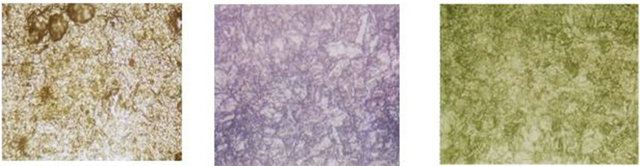
Figure 1. Present the microstructure of 9% Ni steel plate.
to 850 MPa, impact energy at −196˚C reach to 100 J and more [26].
The test specimens are three crews with different thickness size 6, 10 and 14 mm thickness. The chemical and mechanical properties of 9% Ni steel plate according to standards and the actual used according to material certificate as shown in Tables 1 and 2 [27].
2.2. The Welding Process
Welding with stick electrodes however, is still a very flexible and viable process for welding under site conditions, all positions and all materials. A respected economy is also offered when using high recovery electrodes.
So by using SMAW as welding process, electrode E NiCrFe4 with 2.5, 3.2 and 4.0 mm diameter to weld SA553 type I steel test specimen with thickness 6, 10 and 14 mm. The interpass temperature controlled to no more than 80˚C with using low ampere and increasing the travel speed to reduce the heat input.
The chemical composition and mechanical properties of electrode ENiCrFe4 according to construction code standard and actual electrode certificates as shown in Tables 3 and 4 [28].
The geometry of welded joints as shown in (Figure 2) with different root opening according to the using of electrode diameter.
• 2.3. The Mechanical Tests
• Tensile tests have been done on 2 test samples from each welded joint. The test conducted according to the requirements of ASME IX [29] & ASME II part A
Table 1. The chemical composition of 9% Ni steel.
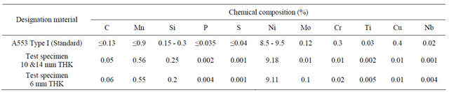
Table 2. The mechanical properties of 9% Ni steel according standards and actual parent metal.
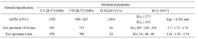
Table 3. The chemical compositions of ENiCrFe4 from code and actual values.
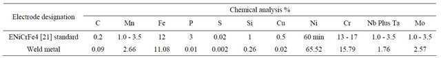
Table 4. The mechanical properties as standard and actual value of ENiCrFe4.
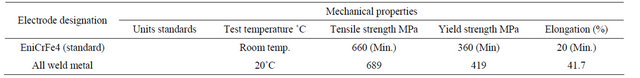
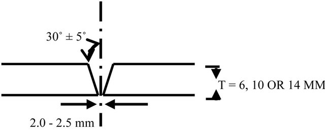
Figure 2. The joint shape for different thickness (6, 10 & 14 mm).
SA370 [30] at room temperature and the samples shape with dimensions as shown in (Figure 3).
• Bend tests applied on 4 test samples from each welded joint with keeping in the consideration the requirements of ASME IX & ASME II part A, SA370 (2 test samples for root bends and 2 for face bend)
• Charpy impact tests have been done in two zones of welded joint weld metal and HAZ zones, 3 test samples for each zone according to ASME IX &ASME II part A, SA370. The test temperature at −196˚C.
• Lateral expansion test conducted according to ASME IX & ASME II part A, SA370.
3. Results and Discussion
3.1. Tension Tests
The tensile properties of the specimens obtained from the welded joints with three different heat input levels are shown in Figures 4-6. The tensile test results show that different heat input levels are all above 690 MPa, which is higher value of the material standards.
From the metallurgical aspects the microstructure of solidification weld deposit can be determine by determine the time of cooling process between 800˚C to 500˚C. So from the heat transfer the next equation to calculate the time of cooling from 800˚C to 500˚C depend on the heat input have been used during the welding of test specimen in 3 dimension.
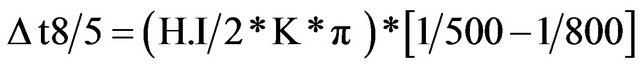 (1)
(1)
where H.I = heat input K = coefficient of thermal conductivity (w/m.K).
According to the Equation (1) the time of cooling from 800˚C/500˚C the time range is between 7.2 to 13.6 sec that related to H.I range from 13.4 to 25.2 KJ/mm.
Where the max tensile strength value exist with applying welding with the lowest heat input, this is due to higher cooling rate that is permission to austenite crystals structure to transform to martensite during welding solidification [25].
The different relation tensile strength and the heat input is shown in Figure 5, where the development of tensile strength value with increase the heat input because
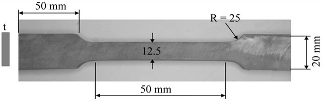
Figure 3. The test sample of tensile stress.
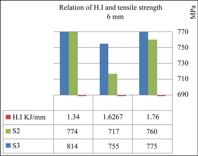
Figure 4. The results of tensile strength test of 6 mm at different H.I.
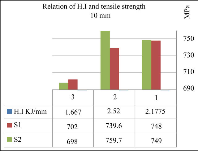
Figure 5. The results of tensile strength test of 10 mm at different H.I.
the lower the interpass temperature effect with still low cooling time.
The initial weld passes preheat the base metal of multipass welds. The effects are greatest on the second pass. As the preheating conditions after the second pass are stabilized, the resultant change in thermal cycle and cooling rate is big significant.
Although the fracture of test specimens done in weld metal zones in some test specimens but with strength values higher than the minimum value of base metal.
The compared results show that heat input has a big
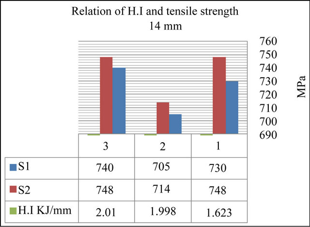
Figure 6. The results of tensile strength test of 14 mm at different H.I.
effect on the tensile properties, with the increase of heat input, the tensile strength of welding joint only increases little.
3.2. Notch-Toughness Tests
The Charpy V notch impact toughness data obtained at −196˚C from the WM and HAZ regions of three weld joints welded with heat inputs levels are presented in Figure 7 which the figure with underline shows the average value of the impact absorbed energy. It is clear that the impact toughness of every zone of the weld joints with three different heat input levels all satisfy the demand of 27 J at −196˚C as required by standard, even when the heat input is in the range of 13.4 - 25.2 kJ/cm.
The results of toughness in HAZ and W.M zones were increased as H.I decreased. Austenite-rich and ferriterich bands are formed during socking because of the redistribution of element C, N and Ni. The austenite enriched of C, N and Ni is still stable [24].
On the other hand from Figures 8 and 9 the toughness results increase as heat input increase to 2.1 KJ this is shown as a results of HAZ & W.M zones and after that the impact value decrease as H.I increase. This return to increase in the cooling rate that increases the probability of present lower binate phase.
The Max. toughness results exist in HAZ zone than the results of W.M zone where the structure of HAZ is mainly martensite and retained austenite affected by the heat input only and W.M is mainly Ni base alloy and has coarse grains.
All results of impact tests related to full size test specimen 10 × 10 × 55 mm.
3.3. Guided -Bend Tests
The bending test at room temperature, all test samples for 6 & 10 thickness were tested for root bend (R.B) and face bend (F.B) but for 14 mm and the bend test were
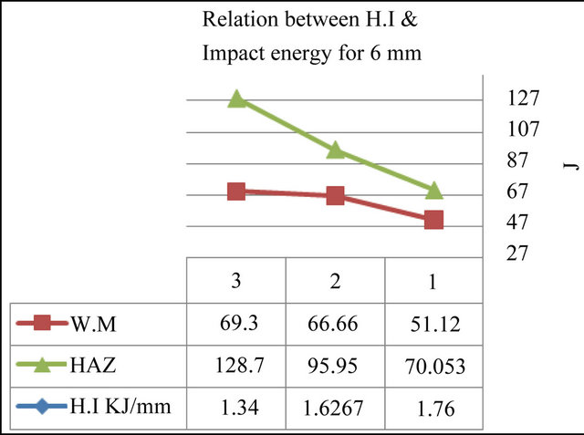
Figure 7. The impact tests results of 6 mm at different H.I.
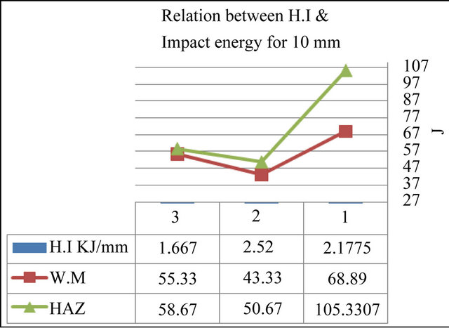
Figure 8. The impact test results of 10 mm at different H.I.
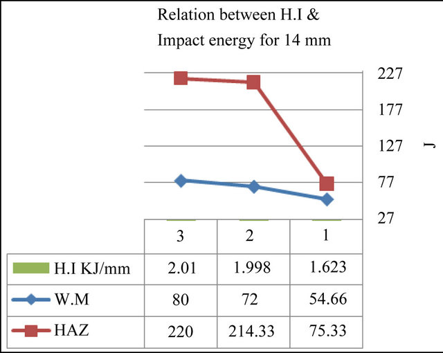
Figure 9. The impact test results of 14 mm at different H.I.
side bend (S.B). The results showed good ductility for all joints & all were free of surface crack or any other surface defect as the following Table 5.
3.4. Lateral Tests
As in Figures 10 and 11 the Lateral test results show that there are different relation between lateral expansion
Table 5. Present the locations and results of bend tests.
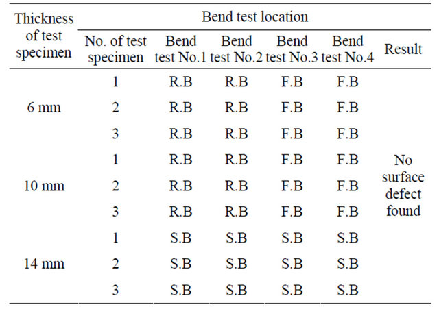
R—Root, B—Bend, F—Face, S—Side.
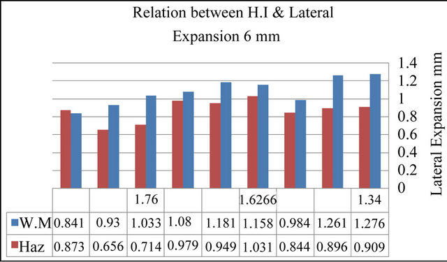
Figure 10. The lateral test results of 6 mm at different H.I.
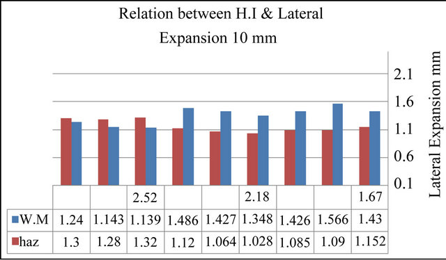
Figure 11. The lateral test results of 10 mm at different H.I.
values in Weld metal(W.M), HAZ and heat input. Where the lateral expansion of W.M zone are decreased as H.I increased, the Lateral test results of HAZ zone are increased as H.I increased.
Although as in Figure 12 the lateral expansion of W.M and HAZ zone are increased as H.I increased and the values of lateral test results of HAZ are greater than the results of W.M zone.
The all results of lateral expansion tests show that the W.M and HAZ zones are more than the value of ASME standard required (0.38 mm) and with average 0.9 mm.
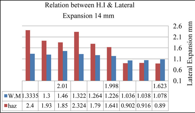
Figure 12. The lateral test results of 14 mm at different H.I.
This is meaning the Welded joint zones are high ductile and for the HAZ zone the structure still uniform and fine grains. The W.M zones are still low values comparing with the values of HAZ due to have a different chemical composition and the main alloy element is Ni.
4. Conclusions
According to the results of this research ,it can be concluded that, the heat input rang from 1.34 to 2.0 KJ/mm is more suitable range for improve the tensile strength and toughness properties of welded joint for the thickness base metal ≤14 mm especially in HAZ zone.
The high cooling rate produced by the using of heat input range has a big effect on the microstructure of welded joint and improved the mechanical properties by eliminating the changing in microstructure of HAZ by creating a martensite and austenite or bainite and austenite. Whilst the effects of cooling rate on the grain of microstructure is development the grain size as in weld metal or existing a fine grain in HAZ zone.
On the other hand the improve of the ductility properties of welded joint increase the transition temperature and enhanced the resistance of brittle fracture and increase the critical stress required to produce the brittle fracture so it has gotten more grantee for the welded joint.
The recommendation is to continue the research for to improve the mechanical properties of welded joint especially the toughness properties more closet to the base metal and reduce the probability of fracture of welded joint due to the thermal shock that can be happened due to any leakage.
5. Acknowledgements
There have been many people who helped me to reaching this far, my sincere thanks to the My supervisors, Prof. ABD El Fatah Kourshid for giving me this great chance in life. Thanks for employees of PETROJET central workshop mechanical lab, for their help in preparing, finishing, and processing the mechanical tests.
REFERENCES
- J. Strömberg and S. S.-H. Pak, “Cost Efficient LNG Storage Tank Constructed by High Productivity Welding,” ESAB, Gothenburg.
- J.-B. Ju, W.-S. Kim and J.-I. Jang, “Variations in DBTT and CTOD within Weld Heat-Affected Zone of API X65 Pipeline Steel,” Journal of Materials Science and Engineering A, Vol. 546, 2012, pp. 258-262.
- M. Lei and Y. Y. Guo, “Formation of Precipitated Austenite in 9% Ni Steel and Its Performance at Cryogenic Temperature,” Acta Metallurgica Sinica (English Edition), Series A, Vol. 2 No. 4 1989, pp. 244-248.
- K. Hickmann, A. Kern, U. Schriever and J. Stumpfe, “Production and Properties of High Strength Nickel Alloy Steel Plates for Low Temperature Applications,” 2005.
- N. Shun-Ichi, M. Toshio and W. Tsunemi “Technology and Products of JFE Steel’s Three Plate Mills,” JFE Technical Report No. 5, Mar. 2005.
- C. K. Syn, B. Fultz and J. W. Morris, “Mechanical Stability of Retained Austenite in Tempered 9Ni Steel,” 1978, Article ID: ADA055240.
- S. Ohkita, “Control of Strength and Toughness in Weld Metals,” Welding International, Vol. 17, No. 9, 2003, pp. 693-698. doi:10.1533/wint.2003.3169
- C. Thaulowa, M. Haugea, Z. L. Zhanga, É. Ranestada and F. Fattorini, “On the Interrelationship between Fracture Toughness and Material Mismatch for Cracks Located at the Fusion Line of Weldments,” Engineering Fracture Mechanics, Vol. 64, No. 4, 1999, pp. 367-382. doi:10.1016/S0013-7944(99)00087-9
- C. Thaulow, A. J. Paauw, M. Hauge, M. Toyoda and F. Minami, “Fracture Property of HAZ-Notched Weld Joint with Mechanical Mis-Matching—Part II,” ESIS Publ., Vol. 17, 1994. pp. 417-432.
- R. Scott Funderburk, “A Look of Heat Input,” Welding Innovation, Vol. XVI, No. 1, 1999.
- J. Wang, Y. J. Li and P. Liu, “Effect of Weld Heat Input on Toughness and Structure of HAZ of a New Super-High Strength Steel,” Bulletin of Material Science, Vol. 26, No. 3, 2003, pp. 301-305. doi:10.1007/BF02707450
- B. K. Srivastava, S. P. Tewari and J. Prakash, “A Review on Effect of ARC Welding Parameters on Mechanical Behavior of Ferrous Metals/Alloys,” International Journal of Engineering Science and Technology Vol. 2, No. 5, 2010, pp. 1425-1432.
- L. H. Xu, J. Zhang and Y. Q. Chen, “Effect of Heat Input on the Microstructure and Mechanical Properties of 07 MnCrMoVR Weld Joints,” Chinese Journal of Mechanical Engineering, Vol. 24, No. 2, 2010.
- J. F. Lancaster, “Metallurgy of Welding”, 6th Edition, Abington Publishing, Abington, 1999. doi:10.1533/9781845694869
- J. Lancaster, “Handbook of Structural Welding,” Abington Publishing, Abington, 1992.
- N. Bailey, “Weldability of Ferritic Steels,” Abington Publishing, Abington, 1994. doi:10.1533/9781845698935
- G. M. Evans and N. Bailey, “Metallurgy of Basic Weld Metal,” Abington Publishing, Abington, 1999.
- M. Lord, “Interpass Temperature and the Welding of Strong Steels,” Welding in the World, Vol. 41, 1998, pp. 452-459.
- T. Takino and R. Fujimoto, “Welding Technology of LNG Tank,” Seitetsu Kenkyu, Vol. 307, 1982, 14229- NS-13.
- K. Agusa, M. Kosho, N. Nishiyama, A. Kamada and Y. Nakano, “Matching Ferritic Filler MIG Welding of 9% Ni Steel,” Kawasaki Steel Technical Report No. 6, September 1982.
- T. Kubo, A. Ohmori and O. Tanigawa, “Properties of High Toughness 9% Ni Heavy Section Steel Plate and Its Applicability to 200 000K/LNG Storage Tak,” Kawasaki Steel Giho, Vol. 30, 1998, 167-KW-20.
- S. Yoshihiro, H. Kohsuke and K. Hisaya, “Welding Heat Input Limit Rolled Steels for Building Structures Based on Simulated HAZ Tests Trans,” JWRI, Vol. 30, No. 1, 2001, pp. 127-134.
- J. Strömberg, “Welding Spherical Tanks Made of 9% Nickel Steel by TISSOT in France,” Svetsaren-ESAB, Göteborg, Vol. 56, No. 2-3, 2001.
- J.-I. Jang, B.-W. Lee, J.-B. Ju, D. I. Kwon and W.-S. Kim, “Effects of Microstructural Change on Fracture Characteristics in Coarse Grained Heat-Affected Zones of QLTProcessed 9% Ni Steel,” Materials Science and Engineering A, Vol. 340, No. 1-2, 2003, pp. 68-79. doi:10.1016/S0921-5093(02)00190-9
- A. Bukvić, Z. Burzić, R. Prokić-Cvetković, O. Popović, M. Burzić and R. Jovičić, “Welding Technology Selection Effect on Fracture-Toughness Parameters of Bi-Material Welded Joints,” Technical Gazette, Vol. 19, No. 1, 2012, pp. 167-174.
- ESAB, “Welding Liquid Natural Gas Tanks and Vessels in 5% and 9% Nickel Steels, Printed in Sweden,” 2001. consumables@esab.se.
- P. Bourges and M. Malingraux, “Fabrication and Welding of Thick Plates in 9% Ni Cryogenic Steel,” INDUSTEEL Co., 2008.
- ASME Sec II Part C “Specifications for Welding Rods, Electrodes, and Filler Metals,” 2010.
- ASME Sec IX, “Qualification Standard for Welding and Brazinf Procedures, Welders, Brazers, and Welding and Brazing Operators,” 2010.
- ASME Sec II Part A, “Ferrous Material Specifications,” 2010.