Materials Sciences and Applications
Vol.3 No.5(2012), Article ID:19199,7 pages DOI:10.4236/msa.2012.35042
Morphology Characterization and Kinetics Evaluation of Pitting Corrosion of Commercially Pure Aluminium by Digital Image Analysis
![]()
1Department of Physics and Chemistry, São Paulo State University, São Paulo, Brazil; 2Department of Materials and Technology, São Paulo State University, São Paulo, Brazil.
Email: *jwjsilva@gmail.com
Received February 28th, 2012; revised March 27th, 2012; accepted April 29th, 2012
Keywords: Aluminium; Alloys; Pitting Corrosion; Morphology Characterization; NaCl Solution; Image Processing
ABSTRACT
The pit morphology and growth kinetics of commercially pure aluminium in naturally aerated NaCl solutions were studied using an image processing method based on reflected light microscopy. In order to distinguish between pits and pre-existing cavities, metallographic examination and statistical analysis were carried out before and after corrosion testing. The results show that the pit shapes and sizes are more dependent on the immersion time than the chloride concentration. Pits are predominantly hemispherical, but they undergo reasonable geometric transitions associated with increased immersion time and occur without significant depth variation. The role of chloride ions is more closely associated with the pit nucleation phenomenon.
1. Introduction
Over the last few decades, there have been considerable advances in the understanding of pitting corrosion. Pitting is a highly localized dissolution of metal that occurs as a consequence of the breakdown of protective passive film on a metal surface. This phenomenon mainly occurs in the presence of aggressive anionic species and is usually caused by chloride ions. Defects that result in nonstoichiometry of the film and/or structural inhomogeneities of the metal are preferential sites for pit nucleation [1-4]. After an induction period, some metastable pits are repassivated, and others are transformed into stable pits of different shapes and sizes. Stable pit growth can be controlled by any electrochemical or chemical reaction: charge-transfer processes, ohmic effects or mass transport. The control reaction can change during pit growth because its mechanism involves the interaction of a metal with an environment that varies as the corrosion reaction proceeds [4-7].
Aluminium and its alloys are used in airframe construction, and pitting corrosion has been widely studied for the purpose of preventing cracking due to stress corrosion [8-9]. Many studies have focused on the pit initiation mechanisms of these materials in chloride media; however, relatively few authors have studied the nucleation and propagation rates of pits [10-17]. For pits initiated by electrochemical experiments, the pit depth or radius dependence on the immersion time (t) may be expressed by the equation k(t-ti)m, where ti is the induction period and k > 0 and 1/6 < m ≤ 2/3 are empirical constants. Generally, it is assumed that pits have a regular geometry. Pits are usually modelled as having cylindrical, hemispherical or conical shapes, but in practice, they have a tendency to assume an irregular geometry associated with increasing size [17-19]. Therefore, equations developed with these assumptions about shape must be considered as only rough approximations.
Maximum pit depth is a more adequate growth parameter because it is not related to pit geometry. For pure aluminium [14-16], this parameter can also be expressed by a simple equation ktn, where n = 1/3 or 1/2, consistent with an ohmicor a diffusion-controlled pit growth rate, respectively. The discrepancy among the reported results may be attributed to different experimental conditions.
Non-electrochemical techniques can be more appropriate for the study of pit growth because they eliminate several problems: a relatively long induction period (ti) for an electrochemical determination of a short duration, the need to determine the electrical current from a single pit, assumptions regarding active pit surface area, and complications associated mainly with hydrogen evolution within the pits that consume a reasonable fraction of the anodic pit density in aluminium. The use of image analysis of surfaces to determine the morphology and extent of localized corrosion has not received much attention. In this study, digital image processing and analysis methods were used for the morphology characterization and kinetic evaluation of pitting corrosion of commercially pure aluminium. For this purpose, the pits were initiated by immersion in naturally aerated NaCl solutions, and their temporal evolution was examined by reflected light microscopy.
2. Experimental
2.1. Chemical Analysis
Commercially pure aluminium (1050-F) plates were supplied by Novelis Brazil Ltda. The chemical composition was determined by atomic emission spectroscopy using a Perkin-Elmer Analyst 300. The chemical analysis is shown in Table 1. This material covers the specifications of the Brazilian standard NBR 6834/06 [20].
2.2. Surface Analysis
Specimens were prepared by cutting up as-received materials. The test was carried out in the perpendicular orientation (transverse) relative to the rolling direction. Thirty parallelepiped sections (15 × 15 × 12.5 mm) were used as the test specimens. Their surfaces were mechanically polished with 220, 320, 400, 600 and 1200 grade emery papers, followed by polishing with 3 µm diamond dust. The surfaces were finished with a 1-µm thick α-alumina suspension. The specimens were immediately electro-polished according to the Class I-1 conditions in the standard guide ASTM E1558-93 [21]. A Buehler Electromet 4 Polisher/Etcher for electrolytic polishing was used to obtain a smooth and electrochemically reproducible surface. The surface of the specimens was examined before and after corrosion tests using image analysis based on reflected light microscopy (LM). The images were captured using a Nikon Epiphot 200 inverted metallurgical microscope coupled to a Diagnostic Instruments Insight Colour QE digital camera. The NIH freeware program Image J [22] was used for image processing, and a macro program was developed to execute all processing and analysis steps, as reported in a previous paper [23]. In addition to the image processing routine, a step with a wand tool was introduced to avoid successive dilations. This introduced an interactive command, which minimize errors due to operator choice. Quantitative parameters such as the area at the cavity mouth and cavity density were systematically determined. Morphological and dimensional analyses were carried out after vertical sectioning using a Buehler Isomet 1000 precision saw. To ensure low deformation of the profile region, the surface was covered with an epoxy resin before cutting and mounting with phenolic resin for mechanical polishing. Pitting analysis was based mainly on Rectangularity or Area-Box (AB) shape parameter, defined as the ratio between the pit area and the minor surrounding rectangular area that encloses the pit. The AB parameter is an effective geometry descriptor, permitting clear separation between conical (0.5 < AB < 0.53), spherical or hemispherical (0.72 < AB < 0.86) and cylindrical pits (AB » 1.0). Figure 1 summarizes the classes for morphological analysis [23]. Transition regions A (near-conical or near-hemispherical pits) and B (nearhemispherical or near-cylindrical pits) represent pits that can evolve for best-defined geometries.
Irregular pits (without geometric elements) present AB values lower than 0.5. A minimum width/depth value of 13.96 for shallowest pits affected by the surface roughness was calculated. This value was obtained of B-5 size and C-1 depth parameters of Standard Rating Charts for pits [16]. Both the surface and cross-section images were captured using the same magnification (200X). A representative number (60) of 1600 × 1200 × 8 bit digital im-
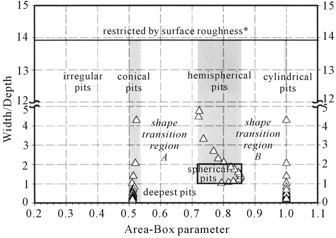
Figure 1. Diagram used for pit geometry classification. Width/depth aspect ratio versus area-box parameter [23].
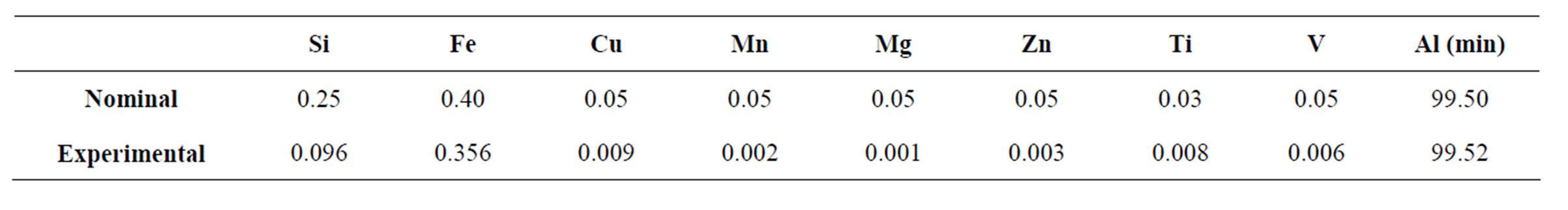
Table 1. Chemical composition of commercially pure aluminium 1050-F (wt%).
ages under bright-field xenon-arc illumination was obtained for each case [24].
2.3. Immersion Tests
Laboratory immersion tests were performed on electro-polished specimens in naturally aerated NaCl solutions for 5 months at 25˚C ± 1˚C [25]. Pit morphology and growth kinetics were studied over a chloride concentration range of 0.0043 to 4.3 mol/L. The first solution contained the maximum chloride concentration permitted in potable water, according to national standards [26]. A vertical cell with a cross-sectional area of ~1.0 cm2 was used as the corrosion cell and basically consisted of a glass tube fixed to the specimen with an epoxy resin.
Two randomly selected specimens were tested for each immersion time. After testing, the specimens were carefully rinsed by immersing in distilled water and then air dried.
3. Results and Discussion
3.1. Specimen Analysis before Corrosion Tests
Microscopic examination of commercially pure aluminium revealed cavities of different shapes and sizes (Figures 2(a) and (b)).
Some cavities were probably induced during the mechanical processing and electrolytic polishing steps. A cavities density of 1919 ± 362 was determined for our test specimens.
The statistical parameters listed in Table 2 seem to indicate that: 1) the geometries of the cavities are not well defined, and in fact, there is no reason that the geometry should be regular; 2) the cavities are wider than they are deep; and 3) some of them are almost closed or subsurface.
It is well known that stagnant immersion conditions favour pitting attacks, so many cavities can nucleate pits.
The shapes and sizes of the pits will be somewhat dependent on the shapes and sizes of the cavities. In this study, we assumed that the pits are cavities whose width and depth were equal or greater than those shown in Table 2 (mean value + standard deviation), and therefore about 90% of cavities were eliminated.
3.2. Specimen Analysis after Corrosion Tests
3.2.1. Pit evolution as a Function of Immersion Time
Figures 3(a) and (b) show the pitting corrosion after 7 days of immersion. This figure reveals that the pits appear be hemispherical and larger than the cavities. The dark region surrounding the pits can be attributed to optical effects provoked by corrosion products, and superposition of pits was also observed.
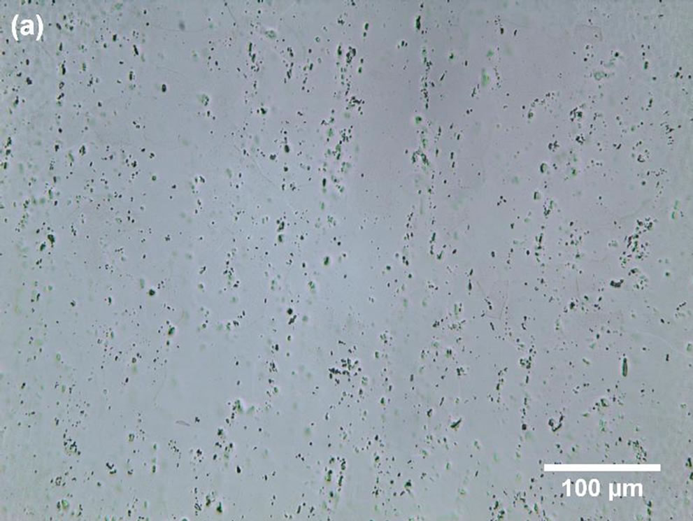
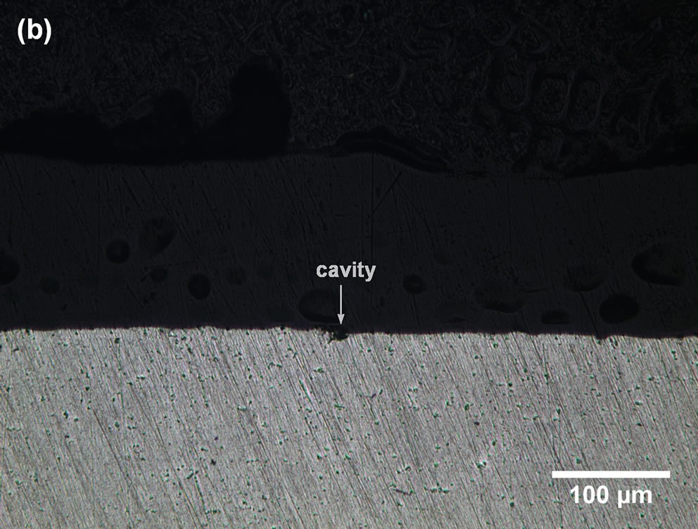
Figure 2. LM micrographs of electro-polished commercially pure Al: (a) surface image and (b) cross-section image.
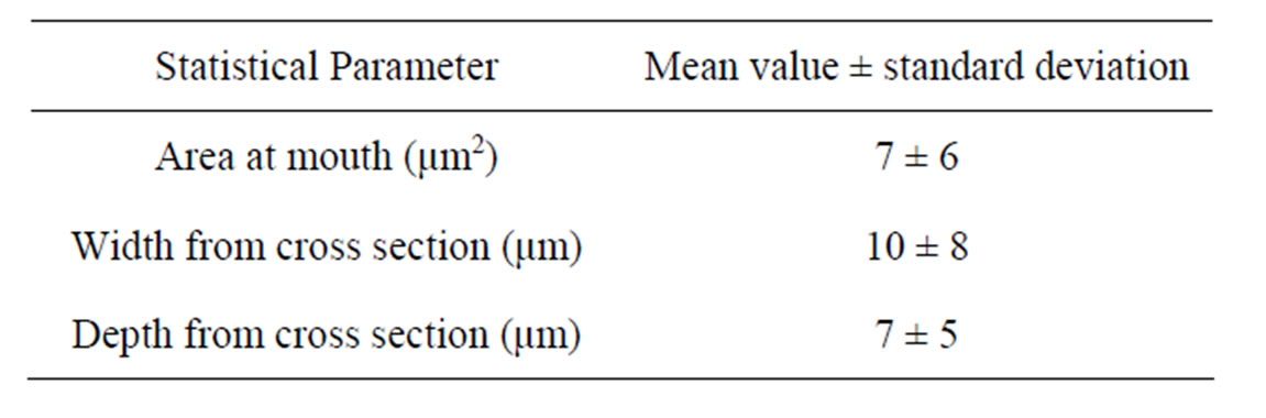
Table 2. Average values of cavities in electro-polished surface.
It is interesting that the pit density remained approximately constant (690 ± 139 pits·mm−2) during this immersion period, which suggests that the surface of the metal possesses a fixed number of active sites (defects) for pit nucleation. A similar conclusion was drawn for stainless steel in NaCl solution in a previous study [5]. At longer immersion times, corrosion products prevented the determination of quantitative parameters. The classification and distribution of the pits were determined from cross-section images as shown in Table 3. This table summarizes the analysis of 60 digital images captured randomly along the cross section of each sample. The results reveal that: 1) at short immersion times, pits are predominantly hemispherical; 2) at long immersion times, pits are predominantly near-conical and near-hemisphe-
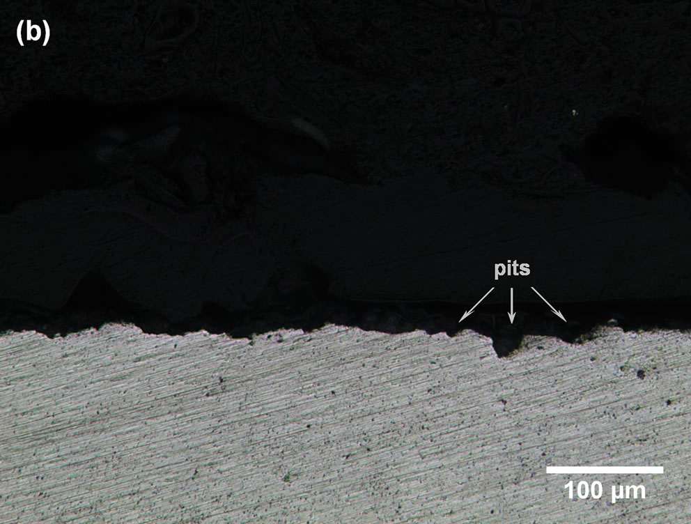
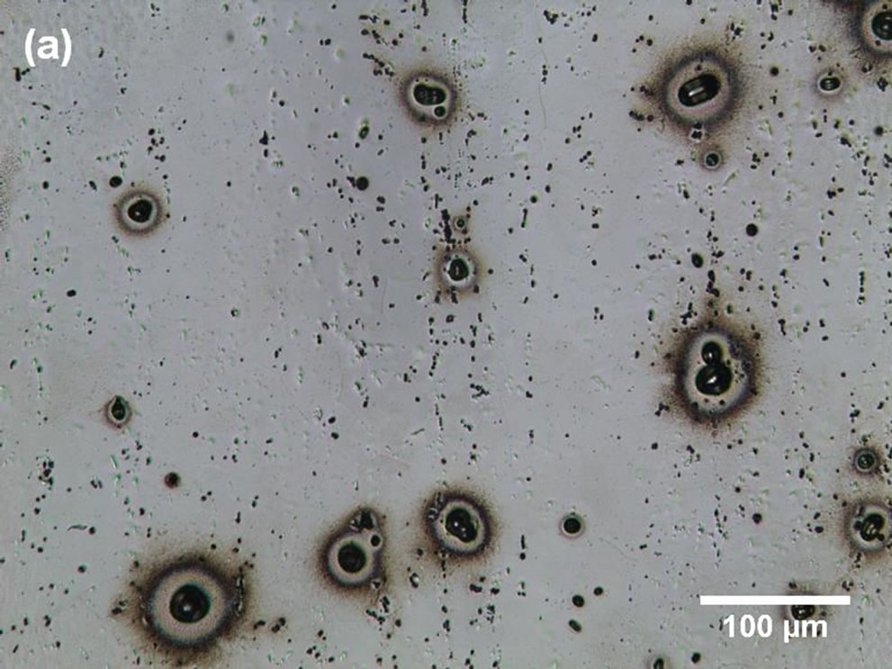
Figure 3. LM micrographs of partially corroded commercially pure Al: (a) surface image and (b) cross-section image.
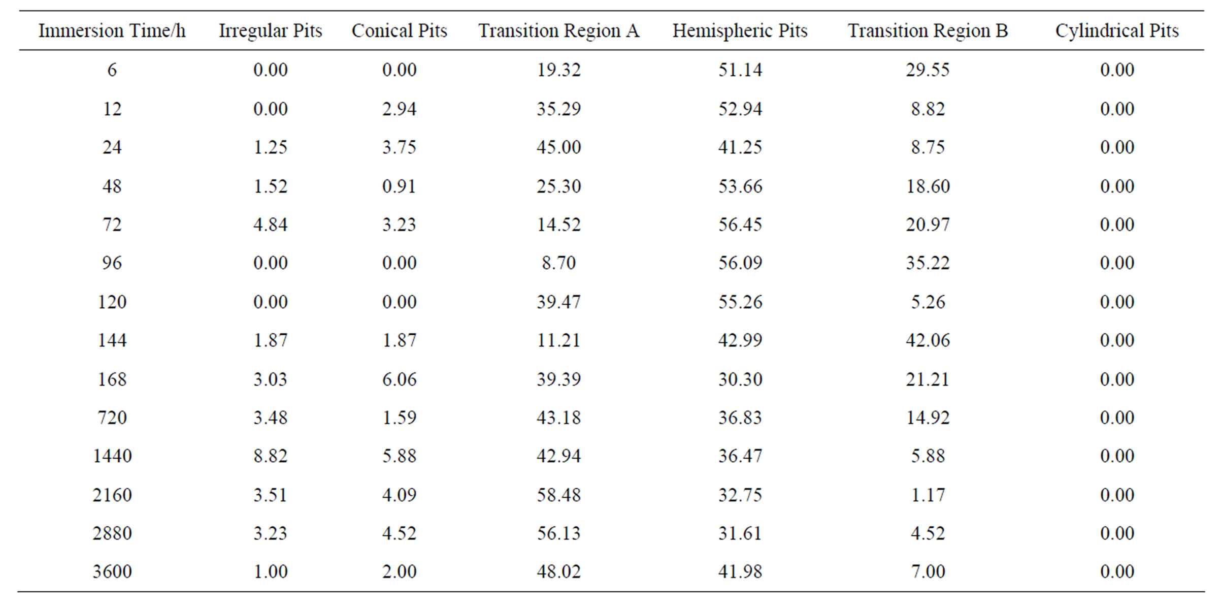
Table 3. Morphology distribution of pits percentages (average values) at different immersion times.
rical; and 3) cylindrical pits were not found. The temporal variation of pit morphology is shown in Figure 4.
Table 4 shows pit width and depth distributions. To diminish the influence of the large cavities (~10% of population) on the statistical treatment of data, we replaced the mean values by the medians [27]. Detailed analysis in this table indicates the following conclusions. 1) The pits are wider than they are deep, which suggests that the rate of metal dissolution is higher at the pit wall than at the pit bottom. 2) Pit depth increases rapidly during the first hours of immersion and then slowly increases until stabilisation. Taking into account that hemispherical, near-hemispherical and near-conical pits represent more than 70% of the pit population, the maximum values of pit depth were found to be close to 19 µm.
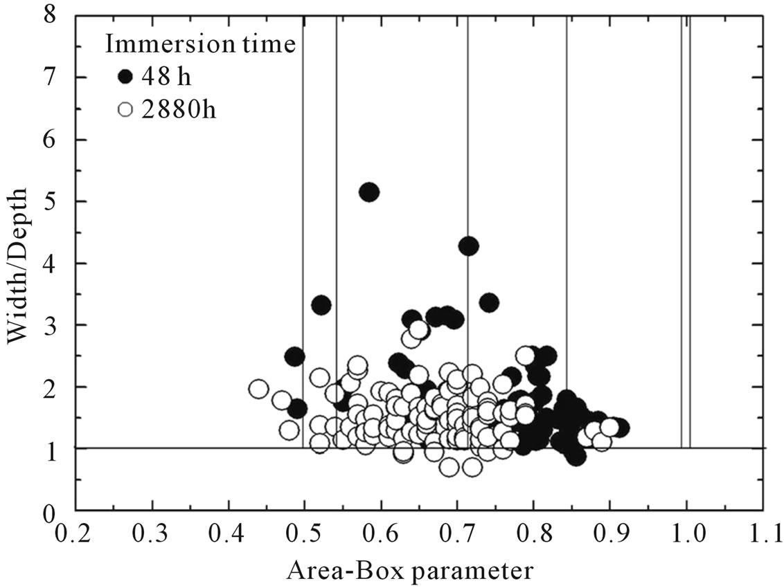
Figure 4. Change in the geometric distribution of pits associated with increasing immersion time.
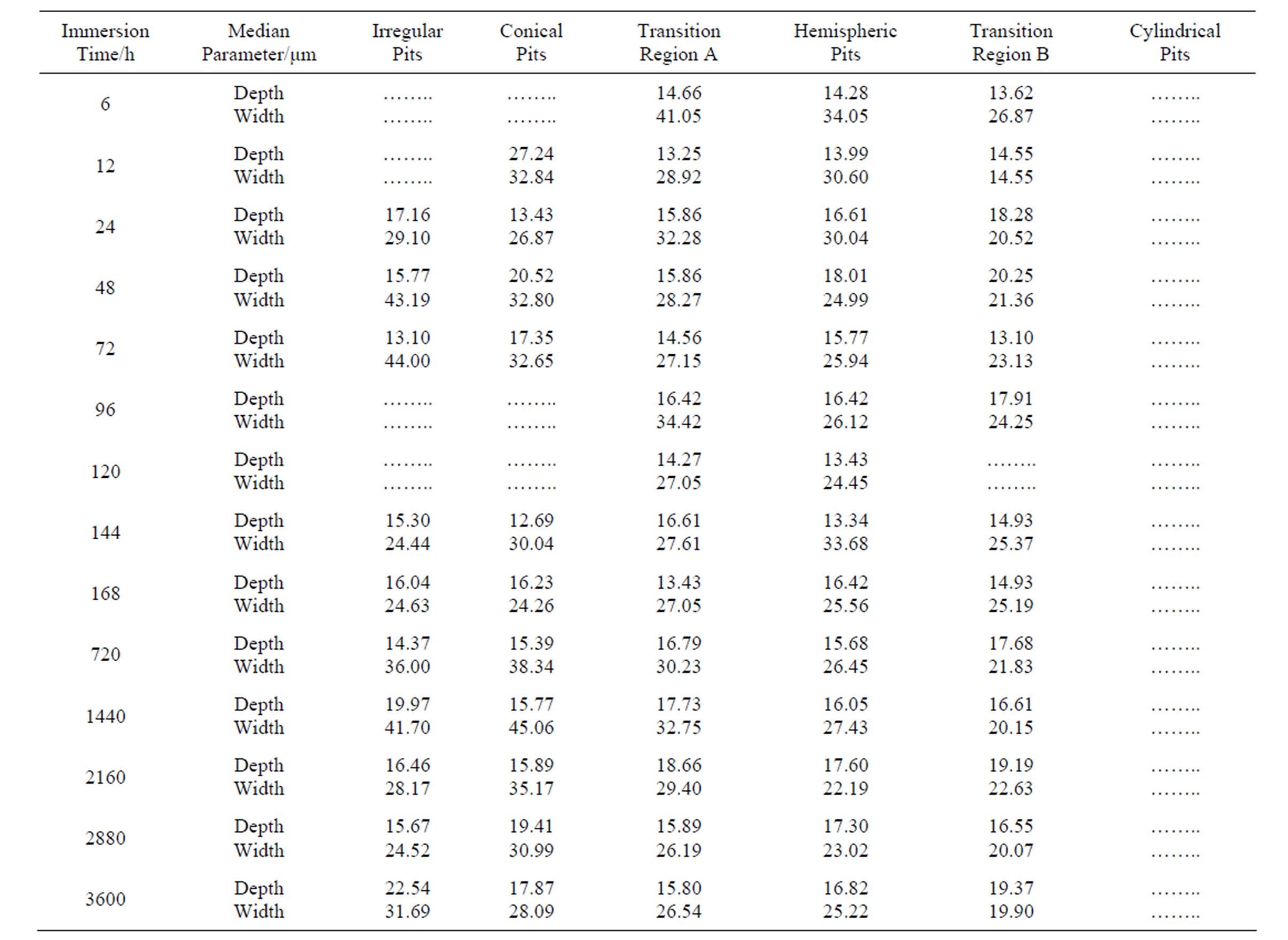
Table 4. Variation of pit width and depth with increasing immersion time.
At the initial stages, pits may be nucleated and then rapidly grow by means of an autocatalytic mechanism [3]. The following increase in the anodic/cathodic area ratio provokes a decrease in the corrosion rate. 3) There is a greater degree of scatter in the width results with time, probably due to superposition of pits.
3.2.2. Pit Evolution as a Function Chloride Concentration
Table 5 summarizes the geometric distributions of pits for different chloride concentrations after 1 month of immersion. Similar conclusions as those for Table 3 were obtained: 1) pits are predominantly hemispherical; 2) the hemispherical, near-hemispherical and near-conical pits represent more than 80% of the pit population; and 3) cylindrical pits were not found.
The growth dimensional parameters are listed in Table 6.
Taking into consideration the more representative class of pits, it is possible to conclude that: 1) the pits are wider than they are deep for each chloride concentration; 2) pit width and depth are not dependent on chloride concentration, suggesting that the chloride ions participate in the pit nucleation mechanism or pit initiation, but they do not participate in the rate-determining step of pit growth. Pit growth is likely dependent upon other events occurring within the pits.
4. Conclusion
Laboratory immersion tests were performed on comercially pure aluminium in naturally aerated NaCl solutions. Pit evolution as a function of immersion time and chloride concentration was studied. In the above-described experimental conditions, the pits are wider than they are deep. Some may have nucleated in cavities of similar geometric characteristics. After nucleation, stable pits rapidly grew. Pit shape and size are more dependent on the immersion time than the chloride concentration, and the role of chloride ions may be best associated with the nucleation or initiation of pits. The pits are predomi-
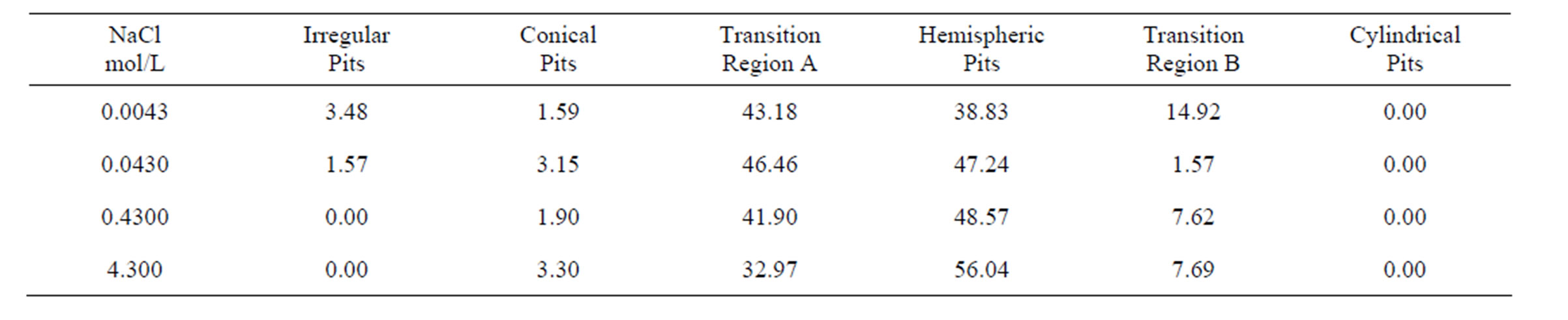
Table 5. Morphology distribution of pits percentages (average values) with increasing chloride concentration.
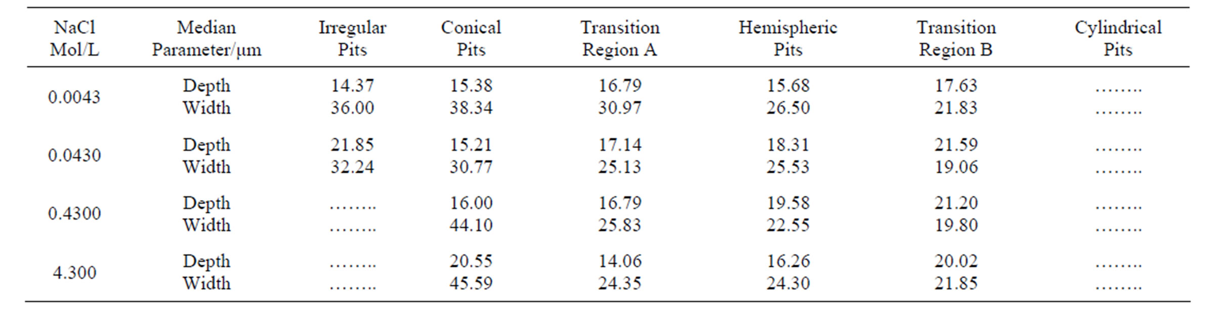
Table 6. Variation of pit width and depth with increasing chloride concentration.
nantly hemispherical, but they undergo a reasonable geometric transition, although without significant depth variation, associated with an increasing immersion time.
5. Acknowledgements
This research was supported by FUNDUNESP (process 01258/2008 and 00601/2011-DFP) and CNPq (processes 305224/2004-2 and 307271/2007-2).
REFERENCES
- G. S. Frankel, “Pitting corrosion of metals,” Journal of the Electrochemical Society, Vol. 145, No. 6, 1998, pp. 2186-2198. doi:10.1149/1.1838615
- A. Seyeux, et al., “ToF-SIMS Imaging Study of the Early Stages of Corrosion in Al-Cu Thin Films,” Journal of the Electrochemical Society, Vol. 158, No. 6, 2011, pp. 165- 171. doi:10.1149/1.3568944
- Z. Szklarska-Smmialowska, “Pitting corrosion of aluminum,” Corrosion Science, Vol. 41, No. 9, 1999, pp. 1743-1767. doi:10.1016/S0010-938X(99)00012-8
- V. McCafferty, “Sequence of steps in the pitting of aluminum by Chloride Ions,” Corrosion Science, Vol. 45, No. , 2003, pp. 1421-1438. doi:10.1016/S0010-938X(02)00231-7
- C. Punckt, M. Bolscher, H. H. Rotermund, A. S. Mikhailov, L. Organ, N. Budiansky, et al., “Sudden onset of Pit Ting Corrosion on Stainless Steel as a Critical Phenomenon,” Science, Vol. 305, No. 5687, 2004, pp. 1133- 1136. doi:10.1126/science.1101358
- J. R. Galvele, “Tafel’s law in Pitting Corrosion and Crevice Corrosion Susceptibility,” Corrosion Science, Vol. 47, No. 12, 2005, pp. 3053-3067. doi:10.1016/j.corsci.2005.05.043
- G. T. Burstein, C. Liu, R. M. Souto and S. P. Vines, “Origins of Pitting Corrosion,” Corrosion Engineering, Science and Technology, Vol. 39, No. 1, 2004, pp. 25-30. doi:10.1179/147842204225016859
- K. S. Rao and K. P. Rao, “Pitting corrosion of HeatTreatable Aluminium Alloys and Welds: A Review,” Transactions of the Indian Institute of Metals, Vol. 57, No. 6, 2004, pp. 593-610.
- S. J. Findlay and N. D. Harrison, “Why aircraft fail,” Materials Today, Vol. 5, No. 11, 2002, pp. 18-25. doi:10.1016/S1369-7021(02)01138-0
- S. M. Ghahari, et al., “Pitting corrosion of Stainless Steel: Measuring and Modelling Pit Propagation in support of Damage Prediction for Radioactive Waste Containers,” Corrosion Engineering, Science and Technology, Vol. 46, No. 2, 2011, pp. 205-211. doi:10.1179/1743278211Y.0000000003
- M. Baumgartner and H. Kaesche, “Aluminium pitting in Chloride Solutions: Morphology and Pit Growth Kinetics,” Corrosion Science, Vol. 31, 1990, pp. 231-236. doi:10.1016/0010-938X(90)90112-I
- Ch. Blanc and G. Mankowski, “Pit Propagation Rate on the 2024 and 6056 Aluminium Alloys,” Corrosion Science, Vol. 40, No. 2-3, 1998, pp. 411-429. doi:10.1016/S0010-938X(97)00147-9
- A. R. Trueman, “Determining the probability of Stable Pit Initiation on Aluminium Alloys Using Potentiostatic Electrochemical Measurements,” Corrosion Science, Vol. 47, No. 9, 2005, pp. 2240-2256. doi:10.1016/j.corsci.2004.09.021
- G. Meng, L. Wei, T. Zhang, Y. Shao and F. Wang, “Effect of microcrystallization on Pitting Corrosion of Pure Aluminium,” Corrosion Science, Vol. 51, No. 9, 2009, pp. 2151-2157. doi:10.1016/j.corsci.2009.05.046
- D. W. Buzza and R. C. Alkire, “Growth of Corrosion Pits on Pure Aluminium in 1M NaCl,” Journal of the Electrochemical Society, Vol. 142, No. 4, 1995, pp. 1104- 1111. doi:10.1149/1.2044137
- Standard Guide for Examination and Evaluation of Pitting Corrosion, American Society for Testing and Materials G46-94, 1999, pp. 169-175.
- T.-S. Huang and G. S. Frankel, “Influence of grain structure on Anisotropic Localized Corrosion Kinetics of AA7xxx-T6 alloys,” Corrosion Engineering, Science and Technology, Vol. 41, No. 3, 2006, pp. 192-199. doi:10.1179/174327806X120739
- J. W. J. Silva, A. G. Bustamante, E. N. Codaro, R. Z. Nakazato and L. R. O. Hein, “Morphological analysis of Pits Formed on Al 2024-T3 in Chloride Aqueous Solution,” Applied Surface Science, Vol. 236, No. 1-4, 2004, pp. 356-365. doi:10.1016/j.apsusc.2004.05.007
- J. W. J. Silva, E. N. Codaro, R. Z. Nakazato and L. R. O. Hein, “Influence of Chromate, Molybdate and tungstate on Pit Formation in Chloride Medium,” Applied Surface Science, Vol. 252, No. 4, 2005, pp. 1117-1122. doi:10.1016/j.apsusc.2005.02.030
- Aluminium and its alloys—Chemical composition classification, Brazilian Standard: NBR 6834, 2006, pp. 1-25.
- Standard Guide for Electrolytic Polishing of Metallographic Specimens, American Society for Testing and Materials E1558-93, pp. 917-928.
- W. S. Rasband, ImageJ, U.S. National Institutes of Health, Bethesda, 1997-2007. http://rsb.info.nih.gov/ij/
- E. N. Codaro, R. Z. Nakazato, A. L. Horovistiz, L. M. F. Ribeiro, R. B. Ribeiro and L. R. O. Hein, “An image Processing Method for Morphology Characterization and Pitting Corrosion Evaluation,” Materials Science and Engineering: A, Vol. 334, No. 1-2, 2002, pp. 298-306. doi:10.1016/S0921-5093(01)01892-5
- Standard Test Methods for Determining Average Grain Size Using Semiautomatic and Automatic Image Analysis, American Society for Testing and Materials E1382-97; 2004, pp. 1-22.
- Standard Practice for Laboratory Immersion Corrosion Testing of Metals, American Society for Testing and Materials G31-72, 1995, pp. 95-101.
- Public water Supply Systems—Designs of Water Treatment Works—Procedure, Brazilian Standard: NBR 12216, 1992, pp. 1-18.
- J. W. Müller, “Possible advantages of a robust evaluation of comparisons,” Journal of Research of the National Institute of Standards and Technology, Vol. 105, No. 4, 2000, pp. 551-555. doi:10.6028/jres.105.044
NOTES
*Corresponding author.