Wireless Engineering and Technology
Vol.4 No.1(2013), Article ID:27648,12 pages DOI:10.4236/wet.2013.41005
Time-Reversal UWB Positioning Beacon for Railway Application
![]()
1Université Lille Nord de France, Lille, France; 2Institut Français des Sciences et Technologies des Transports de L’aménagement et des Réseaux (IFSTTAR), Laboratoire Electronique, Ondes et Signaux Pour les Transports (LEOST), Villeneuve d’Ascq, France; 3Département Opto-Acousto-Electronique (DOAE), Université de Valenciennes et du Hainaut-Cambrésis (UVHC), Institut D’é- lectronique, de Microélectronique et de Nanotechnologie (IEMN), Valenciennes, France; 4Centre National de la Recherche Scientifique (CNRS), Unité Mixte de Recherche (UMR), Villeneuve d’Ascq, France.
Email: bouna.fall@ifsttar.fr
Received September 24th, 2012; revised October 27th, 2012; accepted November 14th, 2012
Keywords: UWB; Time Reversal; Focusing Gain; Channel Model; Power Delay Profile; TDOA; Localization Error
ABSTRACT
This paper studies a new positioning beacon for railway transport using Ultra Wideband (UWB) radio and Time Reversal (TR) techniques. UWB radio has the potential to offer a good level of performance in terms of localization accuracy. Time Reversal channel pre-filtering facilitates signal detection and also helps increasing the received energy in the targeted area. In this paper, we evaluate the characteristics of TR technique in terms of temporal focusing. The theoretical and simulation results for Power Delay Profile, equivalent channel model and focusing gain of TR-UWB are given. We analyze the contribution of Time Reversal associated with UWB technology to enhance the localization resolution. The IEEE 802.15.3a channel models are used to evaluate the performance of this system. In terms of localization error, the theoretical and simulation results show that TR-UWB technique delivers improved performance over the UWB localization approach.
1. Introduction
Guided urban automated transportation systems are progressing significantly nowadays, highlighting many benefits. User’s security and accessibility to these guided transport systems constitute a major issue dealt with many teams. In order to obtain an efficient and safe control and command system of the trains, it is essential to ensure an adequate exchange of information between vehicles and infrastructure and to determine accurately and constantly the absolute localization of the train.
The track to train data exchange is usually called CBTC for Communication Based Train Control. It can use many different radio techniques [1]. The localization system is based on proprioceptive sensors (phonic wheels, Doppler radars…) embarked in the train. This on-board system is coupled to the use of beacons located at ground, on the track, between the rails. These beacons are kilometer markers. They are used to compensate the drift of the localization information computed using the proprioceptive sensors alone, when the train moves. The beacons provide absolute localization information whenever the train passes over them. They are adequately spaced along the track in order to limit the localization drift to a tolerable safe value. In many railway systems, these beacons constitute the only equipment remaining between the rails [2]. Therefore, it could be interesting to remove this last equipment from the track, for example to facilitate track maintenance. In our studied case, the beacon would be situated on the side of the track, a few meters away, therefore not interfering with track maintenance operations.
In this paper, we propose a new solution allows to increase the positioning performances in terms of localization errors and to reduce the cost of track maintenance operations, thus constituting a new beacon realization. This new solution is based on the Ultra Wideband ImpulseRadio technology (UWB-IR) associated to the Time Reversal (TR) technique.
Otherwise, the combination of these techniques could be applied in various areas of the localization, such as the detection and localization of persons-through barriers or to find victims of accidents, especially in the mountains or in mines [3]. Through-the-Wall sensing takes also advantage of TR techniques and this application is very useful in safety and peace-keeping applications.
In this context, the proposed association between UWB and TR techniques for the precise localization of trains is illustrated in Figure 1. It shows the particular case of a railway tunnel. The beacons are geo-referenced. TR-UWB beacons are installed on the side of the track. The TRUWB beacons are kilometer markers. They can also exchange local CBTC information over the UWB radio link. When arriving in the range of the UWB communication, the train computes its absolute localization to the beacons using time of flight information. Localization algorithms such as TDOA (Time Difference of Arrival) and TOA (Time of Arrival) can be used. Moreover, multiple UWB transmitters can be located in a beacon to enhance focusing and availability. The local Channel State Information (CSI) between any beacon transmitter and the virtual optimal beacon localization between the rails is identified a single time during the initial installation. This information is then introduced as pre-filtering data in the different UWB transmitters. Therefore, focusing is obtained in the required position, along the track, potentially improving the absolute localization process [4].
This study evaluates the temporal focusing performance of the time reversal (TR) method using the IEEE 802.15.3a channel models. For these evaluations, theoretical and simulation methods are used. Since the railway localization problem can be considered as a one dimension (1D) problem, we analyse the contribution of TR on the quality of localization in 1D.
This work also aims to verify whether the combination of UWB and TR techniques allows obtaining the decimetre required localization level of precision necessary to the railway application.
This paper is organized as follows: the second part presents the UWB and TR techniques. The third part presents the propagation channel modeling using the IEEE 802.15.3a channel models. The fourth section provides the analytical results of the TR-UWB system in terms of temporal focusing including focusing gain and Power Delay Profiles. The fifth section provides a comparative study between analytical and simulation results of the TR-UWB system in terms of temporal focusing. The sixth section presents the principle of TR-UWB localization
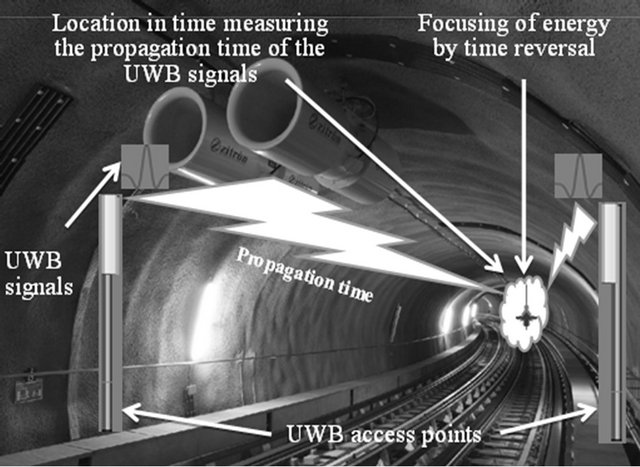
Figure 1. TR-UWB proposed localization system.
and the performance of the proposed solution in terms of localization error. Finally, the conclusion summarizes the results and suggests future work.
2. UWB and TR Techniques for Railway Applications
2.1. Ultra Wideband (UWB) Technology
UWB radio is typically defined as a wireless transmission scheme with a bandwidth over 500 MHz, or occupying 20% or more of the carrier frequency. There are different UWB approaches. In our study, we use an Impulse Radio UWB-IR system. This model involves the transmission of very short pulses occupying a very wide spectrum (Figure 2). The Gaussian waveform and its derivative are usually used. Figure 3 shows the second derivative of Gaussian function that we will use.
A direct benefit of UWB concerns the use of low-cost, small size radio interface circuits [5].
UWB radio technology also offers some potential for railway applications [6]:

Figure 2. Comparison of the UWB spectrum and other wireless radio systems.
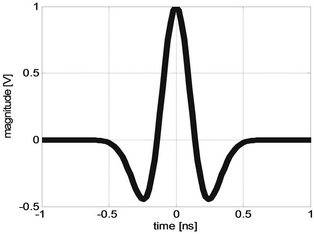
Figure 3. Transmitted pulse (second derivative of Gaussian function).
● It provides potentially high transmission data-rate, using a very large bandwidth;
● It offers high resolution train location because of the fine temporal resolution of the transmitted pulses;
● It adds ability to detect obstacles (radar) due to the impulsive nature of the signals. This capability is essential to detect obstacles in front of the train;
● Availability and robustness to multi-path are inherent to the large frequency bandwidth.
Localization in indoor environments such as tunnels is the subject of two major sources of error, the first being the lack of line of sight between the transmitter and the receiver and the second being the excessive presence of multipath. With the introduction of UWB in wireless communications, it seemed that this technology can provide improvements. However the studies have also raised some major problems like the complexity of the signal processing at the reception. Acquisition of UWB signals is critical, and its fundamental limits [7,8].
In order to solve all the problems facing the UWB, several studies have been conducted associating UWB and time reversal technique [9].
2.2. Principle and Characteristics of Time Reversal (TR) Technique
Classically, Time Reversal has been applied to acoustics and underwater systems [10,11]. It is closely related to retro-directive array in microwave [12,13] and phase conjugation in optics. More recently, it has also been studied for broadband especially for UWB communications [14]. The first Time Reversal experiment using electromagnetic waves in the 2.45 GHz band was reported in [15]. This contribution suggests that the techniques developed for ultrasound might also be used for the electromagnetic case. It is an interesting challenge because in many real environments (buildings or cities), microwaves, using wavelengths between 5 and 30 cm, are scattered off objects such as walls, desks, vehicles and so on, which produces a multitude of paths from the transmitter to the receiver. In such situations, a time reversal system should be able not only to compensate the multipath effect, but also to improve some radio communication parameters, thanks to the many reflections/reverberations that occur.
We propose to use the properties of time reversal [16] for localization systems.
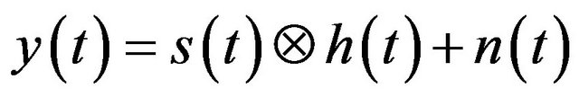
The principle of the proposed TR-UWB system uses three steps. Firstly, we select the signal we want to transmit. In our case, it is the second derivative of the Gaussian function; it is an ultra short pulse. Secondly, the channel impulse response is measured between the transmitter (Tx) and the receiver (Rx) and the channel state information is loaded into Tx. Thirdly, the selected signal and the impulse response are reversed in time and transmitted by Tx in the propagation channel, up to Rx. This TR-UWB principle, represented in Figure 4, can be mathematically described by noting s(t) the transmitted pulse, h(t) the complex impulse response of the channel and h*(–t) the complex conjugate of the time reversed version of h(t). We note y(t) the received signal without TR and yrt(t), the received signal with TR at the receiver. Their expressions are given by:
 (1)
(1)
 (2)
(2)
where  represents the convolution operation and n(t) is the Gaussian noise.
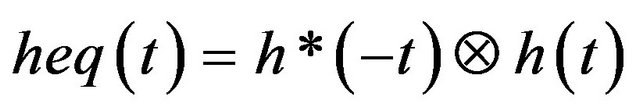
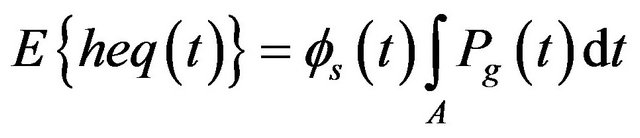
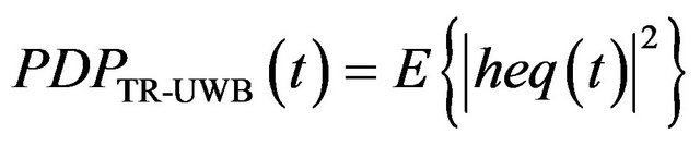
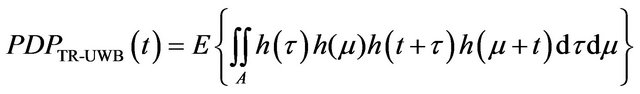
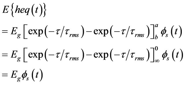
From Equation (2), we deduce the equivalent impulse response heq(t) which corresponds to the autocorrelation function of the channel [17]:
 (3)
(3)
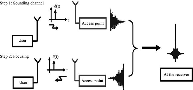
Figure 4. Principle of time reversal technique.
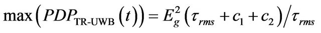
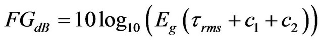
The autocorrelation function is used to evaluate two main characteristics associated to time reversal, i.e., the temporal focusing and the spatial focusing. These characteristics are very beneficial to the UWB system [17, 18]. To study the temporal focusing, we evaluate the Focusing Gain (FG), which is defined as the ratio of the strongest peak in TR received to the strongest peak received by a conventional UWB system [19]. It can be written as:
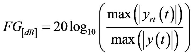 (4)
(4)
Higher FG could potentially translate into higher communication range and higher precision of localization for a localization system as compared to a classical UWB system.
3. IEEE 802.15.3a Channel Model
In this part, we describe the IEEE 802.15.3a channel model. The objective of using this channel model is to characterize the channel impulse response [20,21]. The time reversal would benefit from the complexity of the propagation environment. If the environment is increasingly complex, best will be the focus of energy [22].
The IEEE 802.15.3a model was developed from around 10 contributions, all referring to distinct experimental measurements, performed in indoor residential or office environments [23,24].
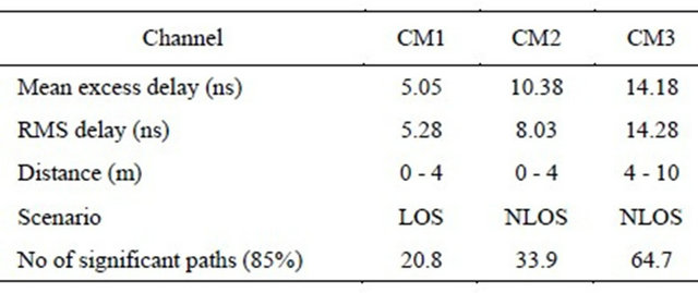
In order to reflect the phenomenon of ray clustering that was observed in several measurement campaigns, the model is based on the Saleh-Valenzuela formalism. Parameters are provided to characterize the clusters and ray arrival rates (Λ and λ), as well as the interand intraluster exponential decay constants (Г and γ). Four sets of parameters are provided to model the four following channel types:
● The channel model CM 1 corresponds to a distance of 0 - 4 m in a LOS situation;
● The channel model CM 2 corresponds to a distance of 0 - 4 m in an NLOS situation;
● The channel model CM 3 corresponds to a distance of 4 - 10 m in an NLOS situation;
● The channel model CM 4 corresponds to an NLOS situation with a large delay spread τrms = 25 ns.
For our study we use the three first scenarios CM1, CM2 and CM3. CM4, generated to fit a large 25-ns RMS delay spread was considered not relevant to our application. Some important characteristics of these scenarios based upon a 167-ps sampling time are shown in Table 1.
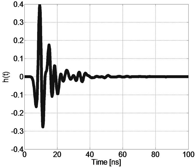
This comprehensive model is a reference for the study of UWB systems. It can be applied in indoor environments and short range conditions. We use these models for performance evaluation in terms of temporal focusing and error localization. Figure 5 presents the impulse response of channel models CM1, CM2 and CM3. The impulse response complexity increases from CM1 to CM3.
4. Analytical Study of Time Reversal Characteristics
In this section, we develop an analytical study of the temporal focusing of time reversal. The study of the temporal focusing is based on the characterization of the propagation channel. For each considered channel model (CM1, CM2, CM3), we determine the equivalent impulse response, the Power Delay Profile and Focusing Gain.
Throughout the study, we denote by:
- s(t): transmitted pulse (derivative Gaussian pulse);
- h(t): Channel Impulse Response CIR;
- h*(–t): conjugated and reversed CIR.
Table 1. IEEE 802.15.3a UWB channel model characteristics.
 (a)
(a) (b)
(b)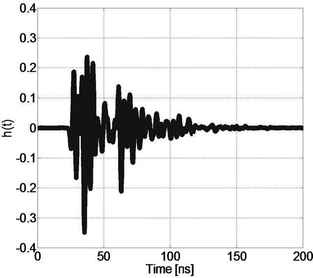 (c)
(c)
Figure 5. Channel impulse response for: (a) CM1; (b) CM2; (c) CM3.
The analytical study in the case of the IEEE 802.15.3a model is done using the statistical moments of interferences that affect the performance of a TR-UWB receiver [25].
For this channel model, we can define CIR by:
 (5)
(5)
The expected value of the equivalent CIR is: [10]
 (6)
(6)
Using the Auto-Correlation Function (ACF) for prototype pulse defined by Equation (7):
 (7)
(7)
The Equation (6) becomes:
 (8)
(8)
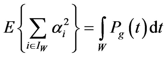
Computing the average energy of the CIR in a generic time window  given:
 (9)
(9)
where  is the random set of multipath components within W and
  referred to Average Power Delay Profile (APDP).
A continuous-time in W is given by a variance of the CIR energy function [26]:
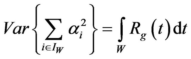 (10)
(10)
where  is the kurtosis delay profile.
Using the equivalence (9) in (8), we obtain:
 (11a)
(11a)
We observe, for 
 therefore
 .
.
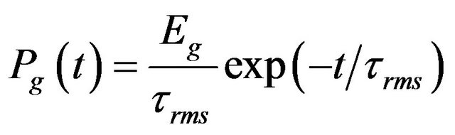
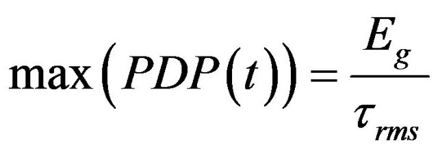
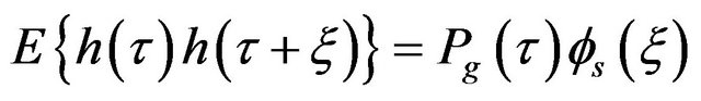
The Average Power Delay Profile Pg(t) is described by a model with exponential decay which is characterized by the average received energy Eg and the rms delay spread τrms of the channel.
 (12)
(12)
For determining Rg(t) we choose a uniform Poisson arrival process with an arrival rate of  ray/s and Nakagami m distributed ray amplitude a simplified version of the Saleh-Valenzuela channel model is [27]:
 (13)
(13)
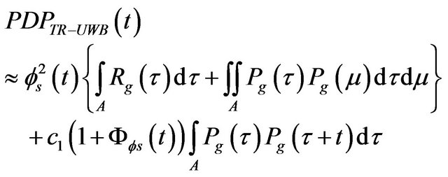
In this case the Power Delay Profile for the equivalent CIR is given by:
 (14)
(14)
It becomes:
(15)
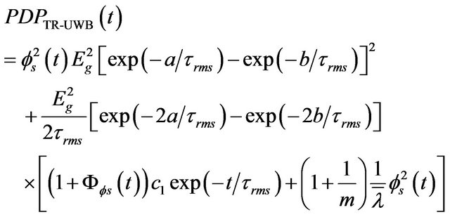
The equivalences (11a) and (15) are developed in Appendix, and their final expressions are given by the Equations (11b) and (16):
 (11b)
(11b)
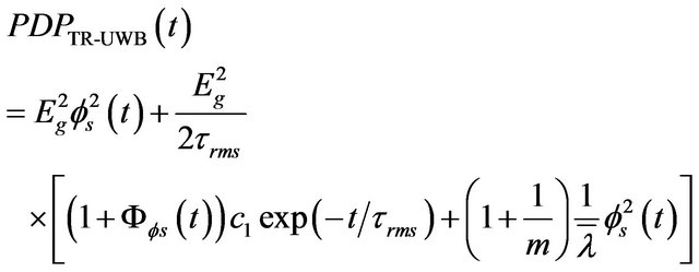 (16)
(16)
The focusing gain presented in (4) can be written in this case as:
 (17)
(17)
with
 (18)
(18)
The correlation function peak is located at zero time shift, therefore:
 (19)
(19)
 (20)
(20)
where 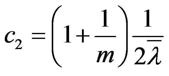
Then, (17) becomes:
 (21)
(21)
5. Analytical and Simulation Results
In this section, we compare the simulation and the analytical results in UWB and TR-UWB cases using IEEE 802.15.3a channel models. Thereafter, we study the contribution of Time Reversal in UWB in terms of temporal focusing.
Tables 2 gives general input parameters for analytical and simulation steps.
We performed a comparative study of the m value appearing in the Nakagami distribution and we considered the four following cases [28]:
m = 0.5: corresponding to a Gaussian situation;
m = 1: is the Rayleigh law, i.e. deep fading;
m = 1.5: corresponding to a severe fading;
m = 4: corresponding to a low fading.
This study showed that the value of m has a negligible impact on system performance TR-UWB. We agreed to choose the value m = 1.5 in the remainder of our studies.
Figures 6(a)-(f) show analytical and simulation results for TR-UWB system, in case of IEEE 802.15.3a channel models. The average over 1000 runs of channels is performed for each channel model (CM1, CM2 and CM3). These results correspond to the equivalent channel impulse response 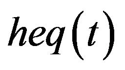 and Power Delay Profile
  for transmitted a second Gaussian derivative pulse. We can observe then, the simulation results are close to analytical results.
Table 3 gives a comparison between analytical and simulation results for IEEE 802.15.3a channel models in term of FG value. This study shows a slight difference between the values of FG to the analytical study and the study by simulation. This can be explained by the sets of input parameters made.
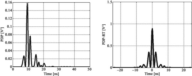
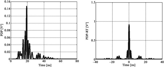
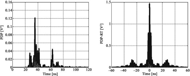
By expanding by simulation the study interval, we can now compare PDP-UWB and PDP-TR-UWB for the 3 considered channel models. Figures 7-9 provide a comparison between PDPUWB and PDPTR-UWB. Considering PDPTR, we obtain a very effective temporal focusing as well as an increase of the amplitude of the power over PDPUWB alone. This translates into the values of FG presented in Table 4.
Table 2. Input parameters for IEEE 802.15.3a channel models.
Table 3. Analytical and simulation results for IEEE 802.15.3a channel models in term of FG Value.
 (a)
(a)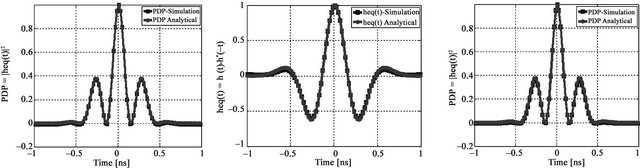 (b)
(b)
Figure 6. Analytical and simulation results for TR-UWB correspond respectively to the equivalent channel impulse response heq(t) and Power Delay Profile PDPTR-UWB(t): (a), (b) for CM1; (c), (d) for CM2; (e), (f) for CM3.
 (a) (b)
Figure 7. (a) PDPUWB; (b) PDPTR-UWB for CM1.
 (a) (b)
Figure 8. (a) PDPUWB; (b) PDPTR-UWB for CM2.
 (a) (b)
Figure 9. (a) PDPUWB; (b) PDPTR-UWB for CM3.
From CM1 to CM3 FG increases, due in particular to the stronger multipath. Indeed, TR takes advantage of the complexity of the channel.
This would be very beneficial for the purpose of locating in confined environments such as tunnels.
6. TR-UWB-IR for Localization
In this section, we carry on this study by evaluating the localization error. We still consider the two preceding UWB alone and TR-UWB techniques. The goal is to estimate the contribution of TR to the location in terms of localization error, as a function of the propagation environment position of a mobile in a 2D plane. To locate the mobile, each base station sends its own signal (recorded and reversed in time in the case of TR). The UWB signals are modulated by an antipodal modulation and coded by a Gold code [29,30], one code per base station. Processing is performed at the mobile (Rx) to determine its position relative to the base stations. The localization error is given by the difference between the calculated position and the actual position of the mobile.
The mobile receives the signals from each base station and performs an adequate signal processing to determine its position, relative to the base stations. Using the TDOA technique, the signal received at the mobile is processed to retrieve the position of the latter [31]. The localization technique (TDOA) is combined with the Chan algorithm to calculate the position of the mobile [32,33]. This technique is illustrated in Figure 10, where S1, S2 and S3 represent the three base stations of known coordinates, M is the mobile to be located. The difference distance between mobile and the ith base station is given by Equation (32):
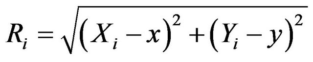 (22)
(22)
where, (x, y) are the unknown coordinates of mobile position, (Xi, Yi) are the coordinates of the base stations. Considering as a reference station S1 (the reference station is the nearest station of the mobile, in the studied case), the difference distance between reference station S1 and other stations is given by:
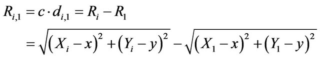
(23)
where, c is the celerity of light, di,1 is the TDOA estimate between reference station and the ith station. Calculating the differences in distance allows us to define a system of nonlinear equation of hyperbolas (Equation (24)), resolvable by Chan’s method [29].
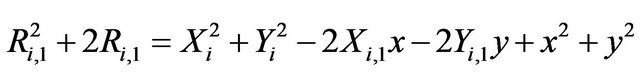 (24)
(24)
For a three base station system, Chan’s method produces two TDOA to determine the coordinates (x, y) of mobile:
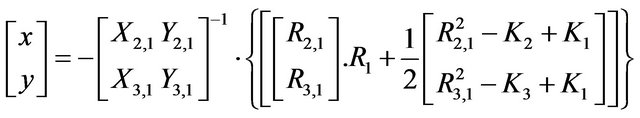
(25)
where:

Our comparison is based on the computation of the Root Mean Square Error of localization between the conventional UWB system and the proposed TR-UWB system. An Additive White Gaussian Noise (AWGN) is also injected in the CM1, CM2 and CM3 models. A large number of iterations are used (1000 iterations). Table 5 presents a comparative study between the UWB system alone and the TR-UWB system; the computed focusing gain and localization errors are indicated using a Signal to Noise Ratio (SNR) of 8 dB. We obtain that the combination of UWB and TR greatly reduces the localization error. Indeed, in the particular case treated, the localization error is 7.45 cm in the case of CM3 for UWB system
Table 4. Focusing gain for CM1 CM2 and CM3.
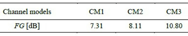
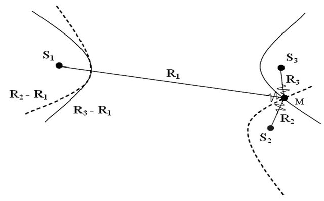
Figure 10. 2-D TDOA localization process.
Table 5. Comparative study between UWB and TR-UWB in terms of focusing gain and error localization (CM1, CM2 and CM3, SNR = 8 dB).
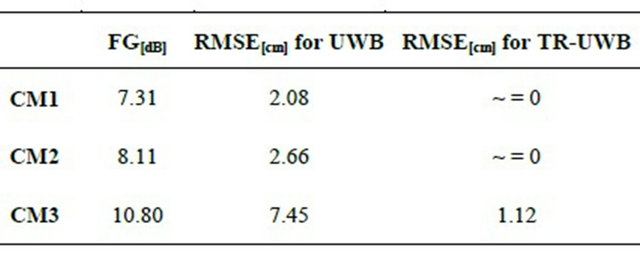
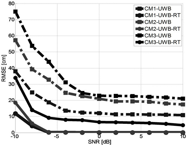
Figure 11. Comparison UWB/TR-UWB, RMSE vs. SNR for channel models CM1, CM2 and CM3.
whereas it is only 1.12 cm for TR-UWB system. This remark also applies to CM1 and CM2.
Different SNR versus were also tested. Figure 11 presents the Root Mean Square Error of localization (RMSE) versus SNR for a large number of CM1 to CM3 realizations. Over the 2 to 10 dB computed range, a stable, considerable improvement is obtained.
7. Conclusion
In this contribution, we presented results obtained working on the association of time reversal and UWB impulse radio for a localization application. The IEEE 802.15.3a channel models are used to perform these studies. The analytical and simulation results have shown that this particular combination can reduce the error localization thanks to the focusing characteristics of time reversal. In future work, we will study different waveforms and modulation types to identify the most appropriate ones. This study will also be conducted with other channel models as well as different single transmitter and multiple transmitter configurations. To validate the analytical and simulation results, experimentations will be soon conducted in an anechoic chamber and a real environment.
REFERENCES
- H. Saghir, M. Heddebaut, F. Elbahhar, J. M. Rouvaen and A. Rivenq, “Train-to-Wayside Wireless Communication in Tunnel Using Ultra-Wideband and Time Reversal,” Transportation Research Part C: Emerging Technologies, Vol. 17, No. 1, 2009, pp. 81-97. doi:10.1016/j.trc.2008.09.003
- M. N. Benslimen, “Recherche de Procedure de Caractérisation de l’Environnement Elecromagnétique Ferroviaire Adaptées au Contexte des Systèmes de Communications Embarqués,” Ph.D. Thesis, Lille University, Lille, 2009.
- N. Maaref, P. Millot, X. Ferriéres, C. Pichot and O. Picon, “Electromagnetic Imaging Methode Based on Time Reversal Processing Applied to through the Wall Target Localization,” Progress in Electromagnetics Research M, Vol. 1, 2008, pp. 59-67.
- B. Fall, M. F. Elbahhar, M. Heddebaut and A. Rivenq, “Time Reversal and UWB Techniques for Positioning System in Transport Applications,” International Symposium on Signal, Image, Video and Communications (ISIVC), Valenciennes, 4-6 July 2012, pp. 1-4.
- M. L. Welbom, “System Considerations for Ultra-WideBand Wireless Networks,” IEEE: Radio and Wireless Conference RAWCON, Boston, 19-22 August 2001, pp. 5-8.
- H. Saghir, M. Heddebaut, F. Elbahhar, A. Rivenq and J. M. Rouvaen, “Time Reversal UWB Wireless Communication-Based Train Control in Tunnel,” Journal of Communications, Vol. 4, No. 4, 2009, pp. 248-256.
- W. Suwansantisuk, M. Z. Win and L. A. Shepp, “On the Performance of Wide-Bandwidth Signal Acquisition in Dense Multipath Channels,” IEEE Transactions on Vehicular Technology, Vol. 54, No. 5, 2005, pp. 1584-1594.
- W. Suwansantisuk and M. Z. Win, “Multipath Aided Rapid Acquisition: Optimal Search Strategies,” IEEE Transactions on Information Theory, Vol. 53, 2006, pp. 174- 193.
- M. Fink, “Ondes et Renversement du Temps,” Bulletin de L’union des Professeurs de Physique et de Chimie, 2005, pp. 25-31.
- M. Fink, “Time Reversal Waves and Super Resolution,” Journal of Physics: Conference Series 124. 4th AIP International Conference and the 1st Congress of the IPIA, 2008.
- A. Derode, P. Roux and M. Fink, “Robust Acoustic Time Reversal with High Order Multiple Scattering,” Physical Review Letters, Vol. 75, No. 23, 1995, pp. 4206-4209.
- L. G. Van Atta, “Electromagnetic Reflector,” US Patent No. 2908002, 1959.
- B. E. Henty and D. D. Stancil, “Multipath-Enabled Super-Resolution for RF and Microwave Communication Using Phase-Conjugate Arrays,” Physical Review Letters, Vol. 93, No. 24, 2004, pp. 1-4.
- T. Strohmer, M. Emami, J. Hansen, G. Papanicolaou and A. Paulraj, “Application of Time-Reversal with MMSE Equalizer to UWB Communications,” Proceedings of Globecom Conference, Dallas, December 2004, pp. 3123- 3127.
- G. Lerosey, J. de Rosny, A. Tourin, A. Derode, G. Montaldo and M. Fink, “Time Reversal of Electromagnetic Waves,” Physical Review Letters, Vol. 92, No. 19, 2004, pp. 1-3.
- X. Liu, B.-Z. Wang, S. Xiao and J. Deng, “Performance of Impulse Radio UWB Communication Based on Time Reversal Technique,” Progress in Electromagnetics Research, PIER 79, Vol. 79, No. 11, 2008, pp. 401-413. doi:10.2528/PIER07102205
- D. Abassi-Moghadam and D. T. Vakili, “Channel Characterization of Time Reversal UWB Communication Systems,” Wiley International Journal of Communication Systems, Vol. 65, No. 9-10, 2010, pp. 601-614.
- C. Zhou, “Time Reversal Ultra-Wideband (UWB) Multiple Input Multiple Output (MIMO) Based on Measured Spatial Channels,” IEEE Transactions on Vehicular Technology, Vol. 58, No. 6, 2009, pp. 2884-8898.
- C. Zhou, “Impulsive Radio Propagation and Time Reversal MIMO System for UWB Wireless Communications,” Ph.D. Thesis, Faculty of the Graduated School, Tennessee Technological University, Cookeville, 2008.
- P. Pagani, F. T. Talom, P. Pajusco and B. Uguen, “Ultra Wide Band Radio Propagation Channels, A Practical Approach,” ISTE Ltd. and John Wiley & Sons, Inc., Chichester, 2008, 239 p. doi:10.1002/9780470611715
- J. A. Gubner K. Hao, “The IEEE 802.15.3a UWB Channel Model as a Two-Dimensional Augmented Cluster Process,” IEEE Transaction on Information Theory, 2006, pp. 1-9.
- I. H. Naqvi, “Application of Time Reversal (TR) Technique to Ultra-Wide Band (UWB) and Multi-Antenna (MIMO) Communication Systems,” Ph.D. Thesis, Institute National des Sciences Appliquées de Rennes, 2009.
- A. Malish, “Ultra Wideband Propagation Channels—Theory, Measurement and Modeling,” IEEE Transactions on Vehicular Technology, Vol. 54, No. 5, 2005, pp. 1528- 1545. doi:10.1109/TVT.2005.856194
- J. A. Gubner and K. Hao, “Analysis of the IEEE 802.15.3a UWB Channel Model,” IEEE Journal on Selected Area in Communications, 2005, pp. 1-8.
- Y. Chen and N. C. Beaulieu, “Moment Based Interference Analysis of CM1, CM2, CM3 and CM4 UZB Systems,” IEEE GLOBECOM Proceedings, 2007, Washington, pp. 3858-3862.
- W. Klaus and P. Marco, “Statistical Analysis of UWB Channel Correlation Functions,” IEEE Transactions on Vehicular Technology, Vol. 57, No. 3, 2008, pp. 1359- 1373.
- A. Adel, M. Saleh, A. Reinaldo and A. Valenzuela “A Statistical Model for Indoor Multipath Propagation,” IEEE Journal Selected Areas in Communications, Vol. 5, No. 2, 1987, pp. 128-137.
- D. P. Dhiraj, “On the Simulations of Correlated Nakagami-m Fading Channels Using Sum of Sinusoids Method,” Ph.D. Thesis, University of Missouri, Columbia, 2006.
- F. Elbahhar, B. Fall, M. Heddebaut, A. Rivenq and J. M. Rouvaen, “Indoor Positioning System Based on the UWB Technique,” IPIN 2011, Guimarães, 21-23 September 2011, pp. 1-4.
- A. Elabed, F. Elbahhar, Y. Elhillali, A. Rivenq and R. Elassali, “UWB Communication System Based on Bipolar PPM with Orthogonal Waveforms,” Wireless Engineering and Technology, Vol. 3, No. 3, 2012, pp. 181- 188. doi:10.4236/wet.2012.33026
- M. Ghavami, L. V. Michael and R. Kohno, “Ultra Wide Band Signals and Systems in Communication Engineering,” Wiley, London, 2007. doi:10.1002/9780470060490
- R. I. Reza, “Data Fusion for Improved TOA/TDOA Position Determination in Wireless Systems,” Master of Science in Electrical Engineering, Faculty of the Virginia Polytechnic Institute, 2000.
- X. Wang, Z. Wang and B. O’Dea, “A TOA-Based Location Algorithm Reducing the Errors Due to Non-Lineof-Sight (NLOS) Propagation,” IEEE Transaction on Vehicular Technology, Vol. 52, No. 1, 2003, pp. 112-116.
Appendix
The Analytical Study of the PDP of Time Reversal
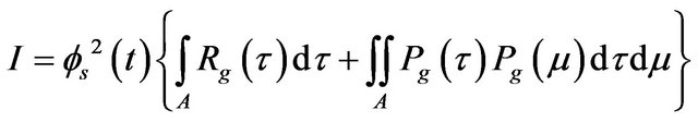
This appendix computes the equivalence (18) that is given by:
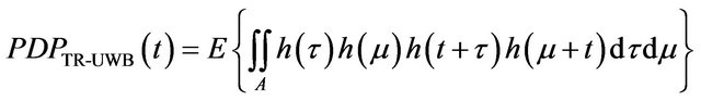
(26)
Substituting 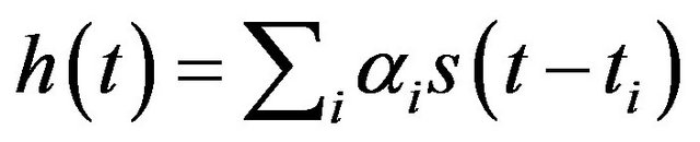 and expanding all the products. We obtain by noticing that
 :
:
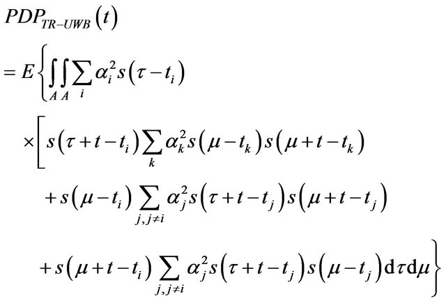 (27)
(27)
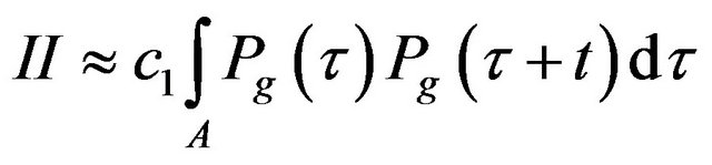
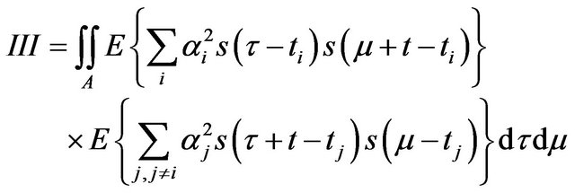
This equation is then composed of three terms named I, II and III:
 (28)
(28)
Knowing that:
 (29)
(29)
Then (28) becomes:
 (30)
(30)
Using the property 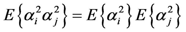 the second term II becomes:
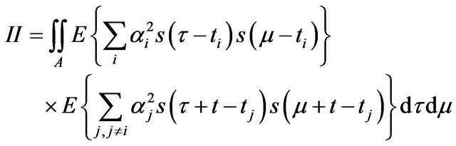 (31)
(31)
By following the change of variable:  we get:
 (32)
(32)
and
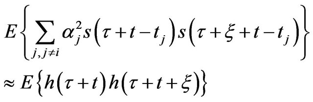 (33)
(33)
According to [16]
 (34)
(34)
Therefore, referring to (4), (31) becomes:
 (35)
(35)
where 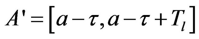
It also defines that: 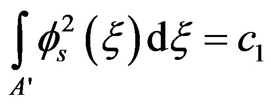 is the autocorrelation energy of pulse, then II becomes:
 (36)
(36)
The third tem III gives:
 (37)
(37)
 (38)
(38)
Also, arguing with the short support of , we can approximate the inner integral by
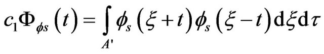
Where  is the pulse auto-correlation function and
  is a normalized time-compressed auto-correlation function of
 , (
, ( ). Therefore III can be written as:
 (39)
(39)
Using this development, (27) becomes:
 (40)
(40)
Substituting (12) and (13) in (11a) and (15) for observation interval 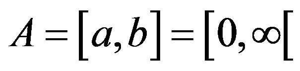 we obtain:
 (41)
(41)
 (42)
(42)
 (43)
(43)