Wireless Engineering and Technology
Vol.2 No.3(2011), Article ID:5763,7 pages DOI:10.4236/wet.2011.23021
Spiral Tuning Stub CPW-Fed UWB Slot Offset, Edge Cleft and Edge Slotted Antennas
![]()
1Department of Electronics and Communications Engineering, Arab Academy for Science, Technology & Maritime Transport, Cairo, Egypt; 2Department of Electronics and Communications Engineering, Misr University for Science & Technology, Cairo, Egypt.
Email: none_658@hotmail.com, {abdelhamidgaafar, abdelaziz_abdelmonem}@yahoo.com
Received April 26th, 2011; Revised May 31st, 2011; Accepted June 10th, 2011.
Keywords: UWB, CPW, Slot Offset Antenna, Edge Cleft Antenna, Edge Slotted Antenna
ABSTRACT
After the release of the unlicensed Ultra Wideband (UWB) spectrum 3.1 GHz to 10.6 GHz for the commercial purposes by the Federal Communications Commission (FCC), industries and academia pay much attention due to its properties of excellent immunity to multi-path interference, high secured data rate, low power consumption, and simple configuration. The feasible UWB antenna design face some challenges including the ultra wide impedance matching, omni directional radiation pattern, constant gain, high radiation efficiency, low profile, compact antenna size and easy manufacturing. Since the CPW fed planar slot antennas have the advantages of wide bandwidth, simple structure, less radiation loss, low cost and easy integration of monolithic microwave integrated circuits (MMIC). In general two parameters affect planar slot antennas impedance bandwidth, the slot width and feed structure. CPW-Fed Slot Antenna with Triangular Tuning Stub, the slot shape could be bow-tie slot, wide rectangular slot, circular slot and hexagonal slot. The impedance tuning can also be performed by using coupling techniques like inductively and capacitively coupled slots, dielectric resonator coupling and other techniques such as using photonic band gap (PGB). Using these techniques, large impedance bandwidth could be obtained but they are quite complicated. Planar slot antennas have two parameters that affect impedance bandwidth, the slot width and the feed structure. The optimum feed structure gives the good impedance matching and the wider slot gives more bandwidth. The proposed antenna in this paper is designed with a compact rectangular slot and a rectangular spiral feeding structure at the interior portion of the feed. The antenna is cleft and slotted at the edge and the effects are studied. The antenna only one of its kinds in structure, small in size and simple design due to less number of design parameters compared with the existing ultra wideband antennas in the literature. The bandwidth, gain, directivity and other antenna parameters are at acceptable level. IE3D method of moments based simulation software is used for this analysis. The proposed antenna design and its experimental result details is presented and discussed.
1. Introduction
After the release of the unlicensed Ultra Wideband (UWB) spectrum 3.1 GHz to 10.6 GHz for the commercial purposes by the Federal Communications Commission (FCC), industries and academia pay much attention due to its properties of excellent immunity to multi-path interference, high secured data rate, low power consumption, and simple configuration [1]. The feasible UWB antenna design face some challenges including the ultra wide impedance matching, omni directional radiation pattern, constant gain, high radiation efficiency, low profile, compact antenna size and easy manufacturing [2]. Since the CPW fed planar slot antennas have the advantages of wide bandwidth, simple structure, less radiation loss, low cost and easy integration of monolithic microwave integrated circuits (MMIC) [3]. In general two parameters affect planar slot antennas impedance bandwidth, the slot width and feed structure [4,5]. CPW-Fed Slot Antenna with Triangular Tuning Stub [6], the slot shape could be bow-tie slot [7], wide rectangular slot [8], circular slot [9] and hexagonal slot [10]. The impedance tuning can also be performed by using coupling techniques like inductively and capacitively coupled slots [11], dielectric resonator coupling [12] and other techniques such as using photonic band gap (PGB) [13]. Using these techniques, large impedance bandwidth could be obtained but they are quite complicated. Planar slot antennas have two parameters that affect impedance bandwidth, the slot width and the feed structure. The optimum feed structure gives the good impedance matching and the wider slot gives more bandwidth [14]. Compact ultra wide band antenna and novel feeding system are the motivations of this study. This can be achieved through using spiral stub with CPW feed as a new feeding system and total dimension of 28 × 21 mm2. Compared to fractal UWB antenna with dimensions of 39.6 mm × 43.5 mm [15], novel compact Ultra wideband antenna fed by CPW with total size of 29 mm × 32 mm [16], small compact T slots UWB antenna with dimension of 30 mm × 30 mm [17], modified elliptical antenna by bending edges and cutting metal sections [18] with total dimension of 90 mm × 65 mm, broadband slot antenna with a circular aperture excited with a planar dipole element with dimensions of 92.52 mm × 37.8 mm [19] and bell-shaped planar ultra wideband antenna with CPW feed line with dimensions of 86 mm × 77.9 mm [20], we could notice that, the proposed structure achieve both novelty and compactness. The proposed antenna in this paper is designed with a compact rectangular slot and a rectangular spiral feeding structure at the interior portion of the feed. The antenna is cleft and slotted at the edge and the effects are studied. The antenna only one of its kinds in structure, small in size and simple design due to less number of design parameters compared with the existing ultra wideband antennas in the literature [21-24]. The bandwidth, gain, directivity and other antenna parameters are at acceptable level. IE3D method of moments based simulation software is used for this analysis [25]. The proposed antenna design and its experimental result details is presented and discussed. The paper next sections are arranged as, antenna design and geometry are first discussed, simulated results including effects of offset lengths, clefting lengths, slotting the antenna edges and radiation pattern are discussed, experimental results and finally, conclusion section.
2. Antenna Design and Geometry
The structure of the antenna is shown in Figure 1. The antenna consists of rectangular slot with width WS and length LS. The tuning stub comprises a rectangular spiral with width Wspt, length Lspt, spiral arm width Wsp and spiral arm separation distance Lsp with five turns. The distance between the tuning stub and feed line is S, WT and LT are the overall width and length of the antenna respectively. In this paper, the dielectric substance (FR4) with thickness of 1.5 mm with relative permittivity of 4.65 is chosen as substrate to facilitate printed circuit board integration. The CPW feed is designed and optimized using IE3D tool and found to be 2.4 mm feed line width Wcf and 0.5 mm ground gap Wcfg. The designed values of the antenna are optimized for the best impedance bandwidth with IE3D tool and the prototype antenna dimensions are given in Table 1.
We can enhance the bandwidth by changing the offset length L1o and best case obtained for L1o – 2.7 mm but with some frequency such as 6.4 GHz very close to –10 dB. We can solve this problem by clefting the antenna edge, best case found when the clefting length be Lc1 = Lc2 = 5 mm but with bandwidth scarifying. Again we can enhance the lower bandwidth by increasing the electrical path through adding slots at the antenna edge. The edge slots width WES1, WES2 and WES3 optimized to be 5 mm, 7 mm and 5 mm, respectively. The optimum slots length LES are equal and found to be 4.75 mm.
3. Simulated Results and Analysis
The proposed antenna analysis and performance are explored by IE3D for impedance better matching through varying one parameter and keeping other parameters constant. The optimal parameter values of the antenna are listed in Table 1 with offset length L1o – 2.7 mm. The
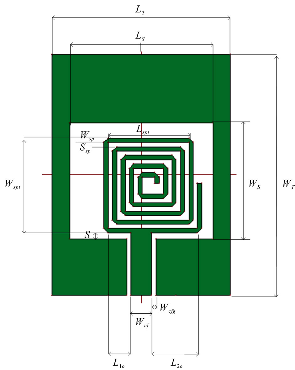
Figure 1. The proposed antenna structure.
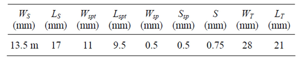
Table 1. The proposed antenna parameter.
of L1o is increased and L2o decreased, the impedance matching is increased over the entire bandwidth which simulated return loss of the proposed antenna is shown in Figure 2, which clearly indicates that the impedance bandwidth of the antenna are 3.67889 GHz (4.11222 GHz –7.79111 GHz) and 0.57444 GHz (3.04889 GHz –3.62333 GHz). The combination of the rectangular slot and the spiral tuning stub leads to ultra wideband antenna performance. The characteristics of the proposed antenna will be affected by field distribution which in turn affected by the proper geometrical selection of the proposed antenna.
3.1. Effect of Offset Lengths Parameter L1o and L2o
For the fixed values of the whole antenna geometry except for the offset lengths L1o and L2o are varied and the simulation results are displayed in Figure 3. If the value
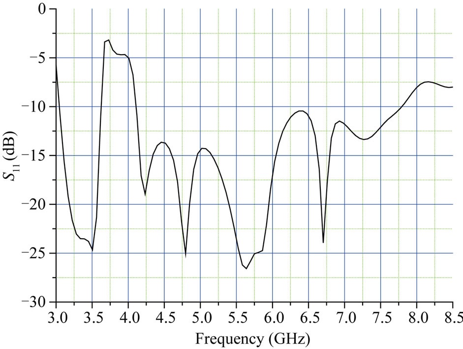
Figure 2. Proposed antenna simulated return loss versus frequency.
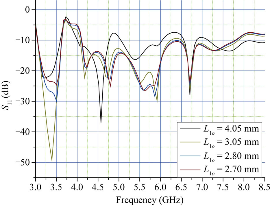
Figure 3. The proposed antenna reflection coefficient versus frequency for different offset length.
clearly point out that these two parameters affect the bandwidth and impedance matching of the antenna. It is found that the optimal length for L1o is 2.7 mm.
3.2. Effect of Clefting Lengths
For fixed values of the whole antenna structure with offset length L1o is 2.7 mm, Figure 4 shows the clefting antenna structure and Figure 5 displays the simulated return loss for different clefting lengths Lc1 and Lc2. The responses clearly illustrate that we can solve the problem of closely value of –10 dB at 6.4 GHz by clefting the antenna edge as shown in Figure 4 with clefting length effect shown in Figure 5 and the best case found when the clefting length be Lc1 = Lc2 = 5 mm but with bandwidth sacrifice.
3.3. Effect of Adding Edge Slots to the Proposed Antenna
The proposed antenna structure is shown in Figure 6 where the slots added at the antenna edge. The effect of bandwidth for different edge slots length LES keeping its widths WES1, WES2 and WES3 fixed to 5 mm, 7 mm and 5 mm respectively and other antenna dimensions are kept fixed shown in Figure 7. It is cleared that enhancing the lower bandwidth achieved but with scarifying the higher one. Figure 7, discloses the profiles of the impedance (3.04889 GHz - 6.72778 GHz) and 0.47667 GHz (7.43667 GHz - 7.91333 GHz) for optimal value of edge slot length of 4.75 mm.
3.4. Radiation Pattern
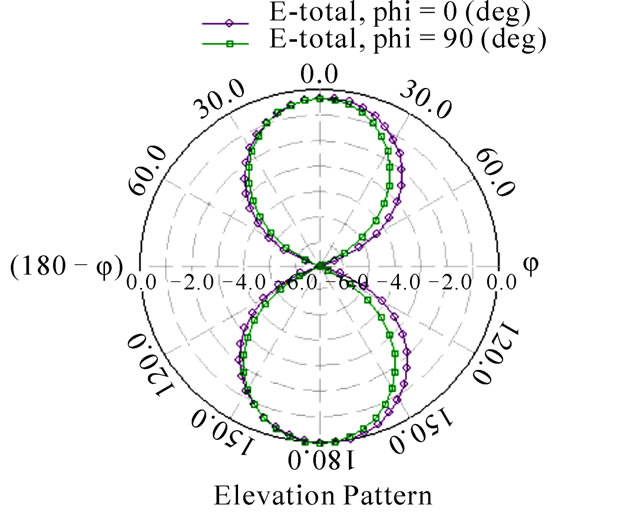
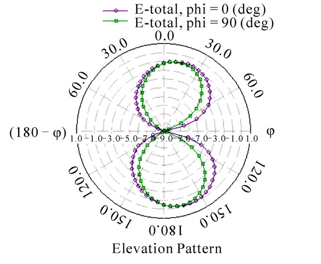
The simulated radiation patterns of the E plane and H plane and other antenna parameters are obtained for different structures are shown in Figure 8-10 for the offset, cleft and edge slotted antenna structure respectively. It is noticed that in H plane and E plane radiation pattern are bidirectional. Other antenna parameters such as gain, directivity and radiation efficiency are achieve acceptable level as shown in Figures 8-10.
4. Experimental Results and Discussions
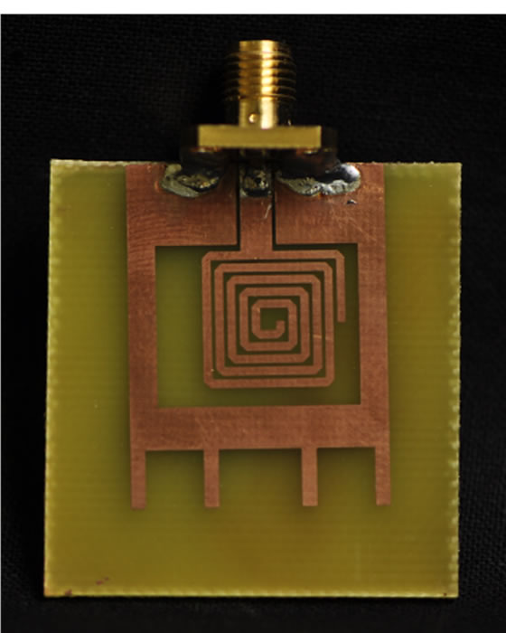
The prototype of the proposed edge slotted antenna as shown in Figure 11(a) was fabricated for optimal values and tested using Vector Network Analyzer (VNA) Agilent HP 8719ES. The return loss is measured and plotted to indicate that it covers wide bandwidth of 3.3 GHz - 7.11 GHz. The simulated and measured return loss of the proposed antenna is illustrated in Figure 11(b) The discrepancy between the measured and the simulated one is due to the effect of improper soldering of SMA connector or fabrication tolerance. The simulation results were obtained by assuming coplanar input port, whereas practically SMA connector was used, the imp effect tran-
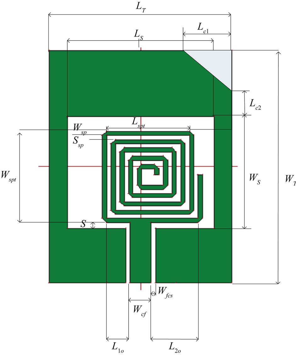
Figure 4. The proposed clefting antenna structure.
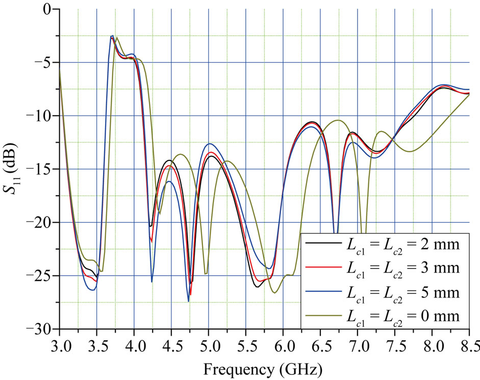
Figure 5. Simulated returned loss versus frequency for different cleft lengths.
sition between SMA feed to coplanar may introduce losses [26] and shift in the frequency. However, good agreement were obtained between measured and computed one.
5. Conclusions
In this paper, a simple antenna structure has been proposed with minimal antenna size and better impedance matching. To enhance the coupling between the slot and feed, a spiral tuning stub is introduced at the anterior
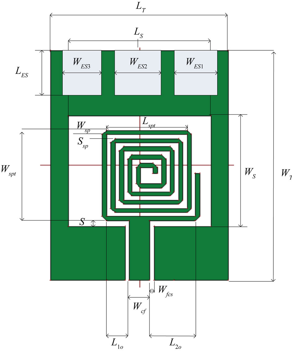
Figure 6. The proposed edge slotted antenna structure.
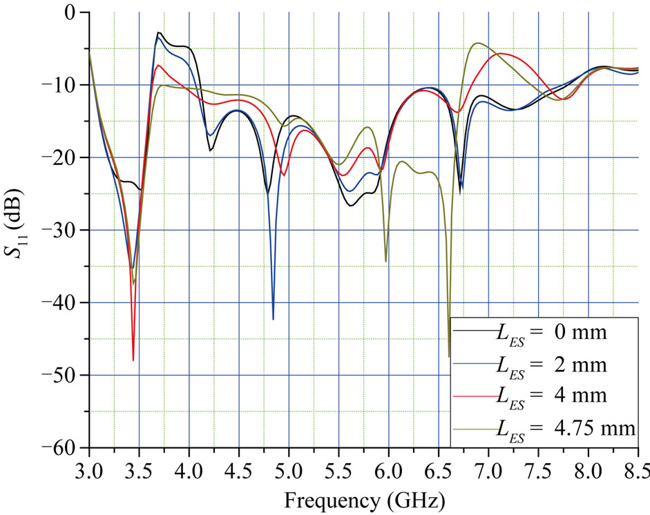
Figure 7. Simulated returned loss versus frequency for different edge slot lengths.
portion of the slot. With the above structural features the overall dimension of the proposed antenna configuration comes around 28 mm × 21 mm × 1.5 mm. Bandwidth of 3.67889 GHz (4.11222 GHz - 7.79111 GHz) and 0.57444 GHz (3.04889 GHz -3.62333 GHz) achieved for the offset antenna and bandwidth of 3.67889 GHz (3.04889 GHz - 6.72778 GHz) and 0.47667 GHz (7.43667 GHz - 7.91333 GHz) for the slotted edge one. The computed and the measured bandwidth analysis of the designed antenna ensures the capability of the antenna working in
 (a)
(a)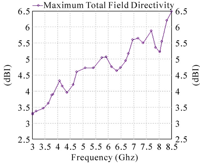 (b)
(b)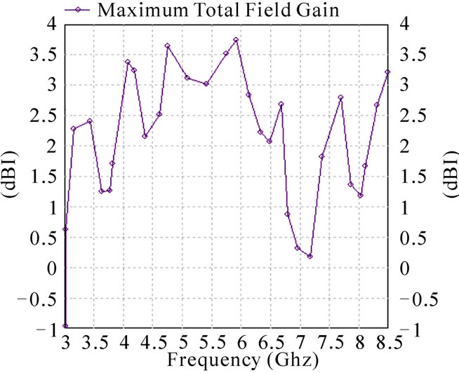 (c)
(c)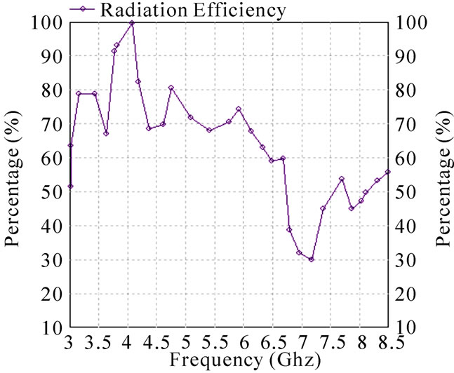 (d)
(d)
Figure 8. (a) Offset antenna structure radiation pattern; (b) Offset antenna structure directivity; (c) Offset structure antenna gain; (d) Offset antenna structure radiation efficiency.
 (a)
(a)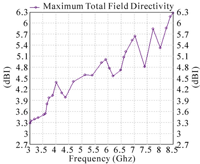 (b)
(b)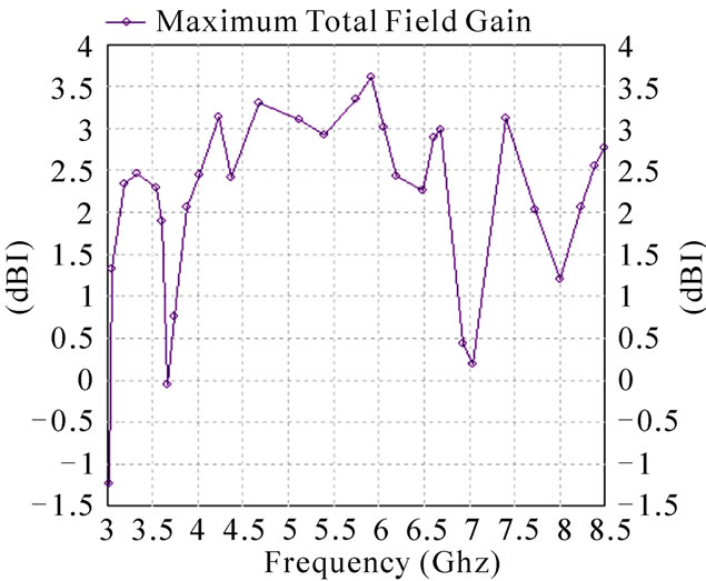 (c)
(c)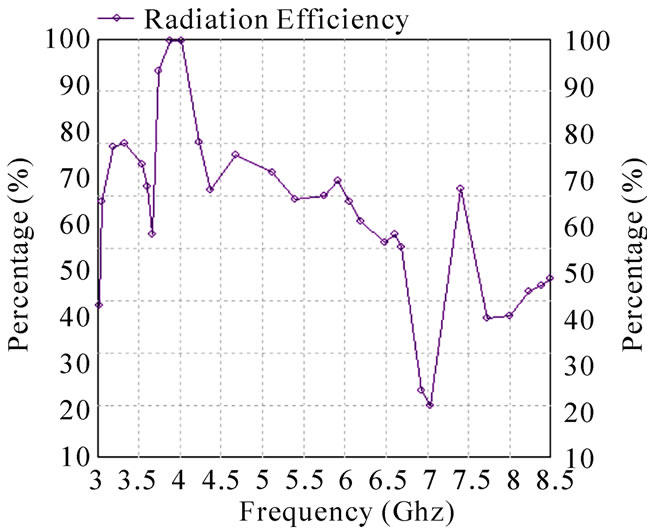 (d)
(d)
Figure 9. (a) Cleft antenna structure radiation pattern; (b) Cleft antenna structure directivity; (c) Cleft structure antenna gain; (d) Cleft antenna structure radiation efficiency.
 (a)
(a)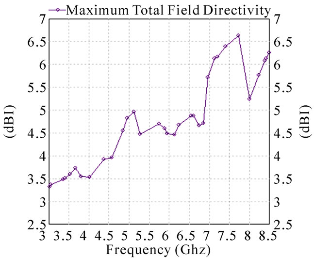 (b)
(b)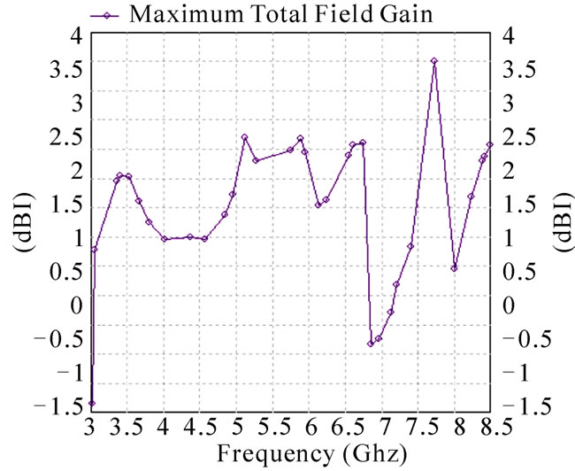 (c)
(c)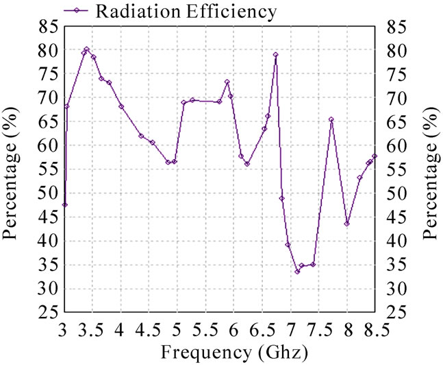 (d)
(d)
Figure 10. (a) Edge slotted antenna structure radiation pattern; (b) Edge slotted antenna structure directivity; (c) Edge slotted structure antenna gain; (d) Edge slotted antenna structure radiation efficiency.
 (a)
(a)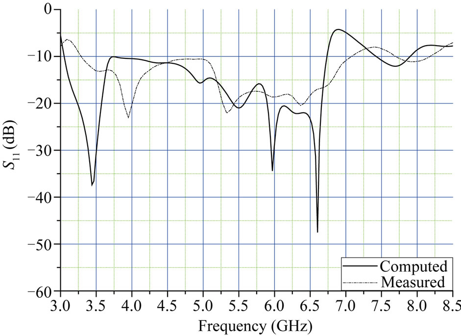 (b)
(b)
Figure 11. (a) Proposed fabricated edge slotted antenna; (b) Proposed edge slotted antenna simulated and measured return loss versus frequency.
the UWB environment. Hence, this type of antenna is suitable for UWB indoor applications.
REFERENCES
- FCC NEWS (FCC 02-48), FCC News Release, 14 February 2002.
- M. Ghavami, L. B. Michael and R. Kohno, “Ultra Wideband Signals and Systems in Communication Engineering,” John Wiley and Sons Inc., New York, 2004. doi:10.1002/0470867531
- R. N. Simons, “Coplanar Waveguide Circuits Components and Systems,” Wiley and Sons Inc., New York, 2001. doi:10.1002/0471224758
- X. Qing and Z. N. Chen “CWB-Fed UWB Monopole Like Slot Antenna,” IET Antenna Propagation, February 2008, pp. 889-899.
- Z. Li and C.-X., Zhang, “Design CPW-Fed Aperture Antenna for UWB Application,” Progress in Electromagnetic Research, Vol. 2, 2008.
- J. William and R. Nakkeeran, “CPW-Fed UWB Slot Antenna with Triangular Tuning Stub,” International Journal of Computer and Electrical Engineering, Vol. 2, No. 4, 2010, pp. 1793-8163.
- L. Marantis and P. Brennan, “A CPW-Fed Bow-Tie Slot Antenna with Tuning Stub,” Proceedings of Loughborough Antennas & Propagation Conference, Loughborough, 17- 18 March 2008, pp. 389-393.
- W. Q. Chen, G. F. Ding, et al., “Design and Simulation of Broadband Unidirectional CPW-Fed Rectangular Slot Antennas,” Proceedings of IEEE International Symposium on Microwave, Antenna, Propagation and EMC Technologies for Wireless Communications, Hangzhou, 16-17 August 2007, pp. 632-635.
- E. A. Soliman, S. Brebels, E. Beyne and G. A. E. Vandenbosch, “CPW-Fed Cusp Antenna,” Microwave and Optical Technology Letters, Vol. 22, No. 4, 1999, pp. 288-290. doi:10.1002/(SICI)1098-2760(19990820)22:4<288::AID-MOP21>3.0.CO;2-E
- K. Sari-Kha, V. Vivek and P. Akkaraekthalin, “A Broadband CPW-Fed Equilateral Hexagonal Slot Antenna,” Proceedings of IEEE International Conference on Computer Systems and Information Technology, Bangkok, 20 September-18 October 2006, pp. 783-786.
- L. Giauffret, J. Laheurte and A. Papiernik, “Study of Various Shapes of the Coupling Slot in CPW-Fed Microstrip Antennas,” IEEE Transactions on Antennas Propagation, Vol. 45, No. 4, 1997, pp. 642-647. doi:10.1109/8.564090
- M. S. A. Salameh, Y. M. M. Antar and G. Seguin, “Coplanar Waveguide Fed Slot Coupled Rectangular Dielectric Resonator Antenna,” IEEE Transactions on Antennas Propagation, Vol. 50, No. 10, 2002, pp. 1415-1419. doi:10.1109/TAP.2002.802097
- L. T. Wang, X. C. Lin and J. S. Sun, “The Broadband Loop Slot Antenna with Photonic Bandgap,” Proceedings of the Twelfth International Conference on Antennas and Propagation, 31 March-3 April 2003, Vol. 2, pp. 470- 472.
- S.-Y. Lin, et al., “A Novel Compact Slot Antenna for Ultra-Wideband Communications,” Proceedings of IEEE Antennas and Propagation International Symposium, Honolulu, 9-15 June 2007, pp. 5123-5126.
- M. Ding, R. Jin, J. Geng, Q. Wu and W. Wang, “Design of a CPW-Fed Ultra Wideband Crown Circular Fractal Antenna,” Proceedings of IEEE Antennas and Propagation Society International Symposium, Albuquerque, 9-14 July 2006, pp. 2049-2052. doi:10.1109/APS.2006.1710983
- A. Subbarao and S. Raghavan, “A Compact Monopole UWB Antenna for Ultra Wideband Applications,” Proceedings of Annual IEEE India Conference, Gujarat, 18- 20 December 2009, pp. 1-4.
- Y. Rahayu, T. Rahman, R. Ngah and P. Hall, “Slotted Ultra Wideband Antenna for Bandwidth Enhancement,” Proceedings of Antennas and Propagation Conference, Loughborough, 17-18 March 2008, pp. 449-452. doi:10.1109/LAPC.2008.4516963
- A. Mehdipour, K. Mohammadpour and R. Faraji-Dana, “A New Planar Ultra Wideband Antenna for UWB Applications,” Proceedings of Antennas and Propagation Society International Symposium, Honolulu, 9-15 June 2007, pp. 5127-5130.
- M. Leib, M. Frei and W. Menzel, “A Novel UltraWideband Circular Slot Antenna Excited with a Dipole Element,” Proceedings of IEEE International Conference on Ultra-Wideband, Vancouver, 9-11 September 2009, pp. 386-390. doi:10.1109/ICUWB.2009.5288841
- A. Mehdipour, A. Parsa, A. R. Sebak and C. W. Trueman, “Planar Bell-Shaped Antenna Fed by a CPW for UWB Applications,” Proceedings of Antennas and Propagation Society International Symposium, San Diego, 5-11 July 2008, pp. 1-4.
- R. Chair, A. A. Kishk and K. F. Lee, “Ultrawide Band Coplanar Waveguide-Fed Rectangular Slot Antenna,” IEEE Antennas Wireless Propagation Letters, Vol. 3, No. 1, 2004, pp. 227-229. doi:10.1109/LAWP.2004.836580
- Y. Lin and K. J. Hung, “Compact Ultrawideband Rectangular Aperture Antenna and Band-Notched Designs,” IEEE Transactions on Antennas Propagation, Vol. 54, No. 11, 2006, pp. 3075-3081. doi:10.1109/TAP.2006.883982
- X. Chen, W. Zhang, R. Ma, J. Zhang and J. Gao, “UltraWideband CPW-Fed Antenna with Round Corner Rectangular Slot and Partial Circular Patch,” IET Microwaves, Antennas & Propagation, Vol. 1, No. 4, 2007, pp. 847- 851.
- Z. Li, C. X. Zhang, et al., “Designs on CPW-Fed Aperture Antenna for Ultra-wideband Application,” Journal of Progress in Electromagnetic Research, Vol. 2, 2008, pp 1-6. doi:10.2528/PIERC08030501
- IE3D 14, Zeland Software, Ins., Fremont, USA.
- S. Licul and W. A. Davis, “Ultra-Wideband (UWB) Antenna Measurements Using Vector Network Analyzer,” Proceedings of IEEE Antennas and Propagation International Symposium, 20-25 June 2004, pp. 1319-1322.