Smart Grid and Renewable Energy
Vol.2 No.2(2011), Article ID:4957,11 pages DOI:10.4236/sgre.2011.22012
Impact of Distributed Generation on Smart Grid Transient Stability
![]()
School of Engineering and Science, Victoria University, Melbourne, Australia.
Email: nurasyik.hidayatullah@live.vu.edu.au, {zahir.paracha, akhtar.kalam}@vu.edu.au
Received February 7th, 2011; revised March 13th, 2011; accepted March 17th, 2011.
Keywords: Smart Grid, Future Grid, Distributed Generation, Flexible AC Transmission System (FACTS), Static VAR System (SVS)
ABSTRACT
In the 21st century Smart Grid and Renewable Energy technologies are an important issue with regards to global climate change problem and energy security. The evolution of current conventional or centralized generation in form of distributed generation and Smart Power Grid (SPG) has great opportunity and potentially can eradicate several issues associated with energy efficiency, energy security and the drawback of aging power system infrastructures. In order to meet the rising electrical power demand and increasing service quality as well as reducing pollution, the existing power grid infrastructure should be developed into Smart Grid (SG) that is flexible for interconnectivity with the distributed generation. However, integrating distributed generation to power system causes several technical issues especially system stability. To make the power grid become “smarter”, particularly in terms of stability, Flexible AC Transmission System (FACTS) device especially Static VAR Compensator (SVC) is used. This paper explores Smart Grid technologies and distributed generation systems. Furthermore, it discusses the impact of distributed generation on Smart Grid, particularly its system stability after installing distributed generation in the Smart Grid. This was done by examining the system stability during interconnection and faults on the system and validated with Dig-SILENT Power Factory Software V 13.2.
1. Introduction
The current electric power industry is undergoing major changes from being centralized generation into decentralized generation. The advances in technology have created rapid growth in the utilization of distributed generations which leads to energy market becoming more attractive and competitive. Moreover, due to electricity deregulation, environmental issues as well as government incentives, this technology has created interest in development further amongst industrial countries throughout the globe. In addition, these issues also results in the Smart Grid platform to end the traditional electric power industry which traditionally was vertically integrated and congested resulting in a higher energy costs.
Nowadays, most of aging and large remote power system stations with central dispatch suffers from disturbances due to lack of intelligent interoperability units. The system also becomes vulnerable when utility abnormalities are present, for example on protection or failures to control coordination and human operation errors. Therefore, there is a need to transform this model into Smart Grid that can enhance power quality and fully integrate with advanced grid elements such as intelligent sensing and digital metering.
Smart Grid is recognized as a new platform for future power industry. The rapid rise on this issue is also leading to the fast growth of distributed generation technology markets such as in fuel cells (FC), photovoltaic (PV), wind turbine (WT) and energy storage (ES). This trend will have profound impact on future electricity technology which allows Information and Communication Technologies (ICT) and advanced power electronic devices to be installed and embedded throughout the network. This is the challenge where current bulk generation and distributed generation will co-exist with higher power reliability and quality in the form of Smart Grid. To emphasize these, this paper will provide a fundamental understanding of distributed generation issues and framework of Smart Grid. Lastly, it finishes off by providing an analysis impact of DG on Smart Grid transient stability.
2. Overview of Distributed Generation, Smart Grid and SVC Technologies
2.1. Distributed Generation
Distributed Generation (DG) technology incorporates wind turbines, micro turbines, photovoltaic systems, fuel cells, energy storage and synchronous generator applications to supply active power to distributed systems connected close to the consumers load. This concept is becoming a major player for Green House Gases (GHG) mitigation and power system reliability. Therefore, many developed countries such as Australia, are encouraging DG utilization for local power source and to avoid concentration of new power system transmission or distribution construction.
The increasing number of DG connection to the grid for the last decade proves that DG intrinsically offers various technical, economical and environmental advantages for customers, utilities and power operators. However, the presence of DG in the current existing power system has an impact on its operation and configuration. Moreover, since most of current aging power system is considered as passive system and with the insertion of DG, the network becoming active system where both of them can act as power sources.
Various studies in the past examined the impact of DG in power system and identified some vital aspects concerning their operation and connection. In reference [1] the analysis on change of power flow direction in corporation of DG integration is verified. In reference [2] the influence of DG on system reliability and stability during peak load is investigated whilst reference [3] focuses on system protection as the short-circuit fault level on the network tends to increase due to DG connection. Reference [4] investigates the voltage variation and protection by comparing the real system behavior with software simulation. The authors conclude that the level of transformer tap changer is increased with an increase on the penetration level of DG. Reference [5] has also reviews the impact of DG on distribution system (DS). At present DG provides much benefit in order to improve voltage quality, loss reduction and reliability. Reference [6] also shows that during interconnection to the distribution network, DG unit can be operated under island mode. It highlights the interconnected DG performance and shows this is greater during islanding condition, especially from security and quality of supply point of view. In addition, the study in [7] demonstrates the positive impact of DG on DS where during faults period, the rotor angle deviation and voltage drop are found to decrease. It means that the transient stability of the system improves with an increase in the penetration level of the DG.
However, overall these research scenario investigates the technical impact of DG on DS where almost all of them are coupled to the medium and low voltage levels. Moreover, none of the research scenario deals with the issues from Smart Grid perspectives. With the presence of Smart Grid concepts and rapid growth of DG and Smart Grid technologies, it is critical to evaluate the system performance precisely. Thus, the framework and concepts of Smart Grid can be applied appropriately and this avoid degradation of power quality and reliability.
2.2. Smart Grid [8]
Nowadays, the intelligent automation on electrical distribution network has been driving the development of future power system like Smart Grid, which might lead to the network model being changed and certainly this will change the electric network operations. Smart Grid is a relatively new concept for future power system that integrates electricity and communication on power system network, which supplies digital information on real time network operation for the operator and ultimately the consumer.
The main characteristics of Smart Grid are self-healing, empowering the customers, improving power quality and ability to accommodate various distributed generation. In addition, advanced control methods, digital sensing and metering, advanced grid devices such as FACTS (Flexible AC Transmission Systems) and SCADA (Supervision Control and Data Acquisition) system are few of the major technologies involved in the implementation of Smart Grid. FACTS is alternating current transmission system device used to enhance control ability and increase power transfer capability based on power electronic and other static controllers, meanwhile the SCADA system refers to the control and communication data system used for operation, monitoring and controlling power system grids. However, the standard of smart grid, how all elements are connected with each other and how the communication or energy flow works still remains the major concerns for enabling Smart Grid implementation.
The National Institute of Standard and Technology (NIST) reveals that there are seven important Smart Grid areas that need to be addressed to make the grid “Smarter” including; bulk generation, transmission, distribution, customer, operation, market domain and service provider [9]. These domains are integrated based on the conceptual model of Smart Grid as shown in Figure 1. As can be seen from the figure, it is obvious that Smart Grid is an integrated system which involves complex co-ordination strategy for implementation. In addition, Smart Grid technology broadens power knowledge and involves interdisciplinary research area such as: communication, automation, sensor and control. Furthermore,
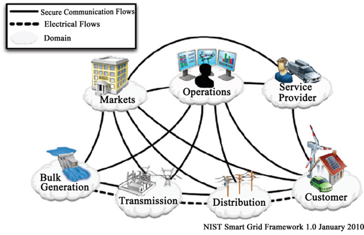
Figure 1. Smart Grid topology network [9].
Smart Grid also requires advanced technology to make the grid as an ideal “Smart Grid”. Nevertheless, due to the complexities of the system, it is unclear and even confusing to define the networks being “smart” if a few of its key characteristics are neglected. Instead, it is preferable to consider the term “Smart Grid” as the chance to enhance the power system performance and improve operational capabilities [8,10].
2.3. Static VAR Compensator (SVC)
FACTS controller history initially began when Hingorani proposed the scheme of power compensation in electrical power system using power electronic applications [11]. Afterward, numerous researches were conducted on the application of FACTS using self commutated semiconductor and thyristor in transmission system. Originally, FACTS devices were developed for transmission systems which consisted of electrical conductors that have resistance, inductance and capacitance (R-L-C). The capacitive and inductive reactance in the transmission line generates and absorbs reactive power. The reactive power that flow along the line often causes further loss in the resistance of the conductor. For this reason FACTS device is required to enhance the power transfer capability and stability in the transmission system. However, for the last decade this concept has been extended for improving power quality on distribution systems operation as well [12]. The application shown in [12] is to control and maintain the system stability where in the distribution level most of the loads are non-linear or dynamic.
Flexible AC Transmission System is one of the advanced technologies used for power system compensation. The devices including Static VAR Compensator (SVC), Static Synchronous Series Compensator (SSSC), Static Synchronous Compensator (STATCOM), Thyristor-Unified Power Flow Controller (UPFC), Thyristor Con-trolled Series Compensator (TCSC), Thyristor-Switched Series Capacitor (TSSC) and Thyristor Controlled Reactor (TCR) etc. These devices have many configurations, commonly it can be classified into series-connected controllers, shunt-connected controllers and a combination of them. The detail description of series and shunt-connected controller can be found in [11].
Static VAR Compensator (SVC) is “a shunt-connected static VAR generator or absorber whose output is adjusted to exchange capacitive or inductive current so as to maintain or control specific parameters of the electrical power system (typically bus voltage) [11]”. SVC is based on thyristor-controlled and switched shunt component without gate turn-off capability. It is a variable impedance device using back to back connected thyristor valves to control the current flow through reactor. SVC as a control device offers fast response time and much faster than traditional mechanically switched reactors or capacitors. The configuration of SVC as shown in Figure 2 consists of two main components and their combination:
• Thyristor-controlled and Thyristor-switched Reactor (TCR and TSR)
• Thyristor-switched Capacitor (TSC)
TCR and TSR constitute of a shunt-connected reactor controller using pair parallel back to back-connected thyristor. Using phase angle control, TCR generates an equilent and constant variable inductive reactive power from zero to maximum. Whereas, TSR is controlled without phase angle control which results in a step change in retance and provides fixed inductive admittance.
TSC has similar operational characteristic and composition as TSR. It consists of a back to back thyristor pair in series with capacitors. The TSC is not continuously conrolled because of transient phenomena at switch-on, however instead is switched on and off independently. Therefore, TSC cannot inject a reactive current with variable amplitude into the system. The transient phenomenon in TSC does not generate harmonics but if they appear, it isnot a serious problem [13].
3. Equal Area Criterion for Transient Stability Analysis
It is well known that large or small-scale integration of distributed generation may have significant impact on power system stability with respect to the rotor angle, voltage and frequency stability. Reactive power compensation and voltage control is fundamental to make the grid become smarter. Without this control, the presence of distributed generation may potentially cause system collapse. Therefore, a dynamic shunt reactive power compensator such as SVC is required to mitigate these issues since it can be used to enhance transient stability margin in power system. The potential effectiveness of SVC on transient stability enhancement can be examined through
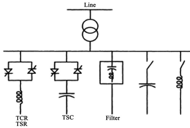
Figure 2. SVC configuration [11].
the following discussion.
As depicted in Figure 3, assume that a single power generation machine with interconnecting lossless lines have a reactance (X). Denoting the terminal voltages of generator machine and the infinite bus by  and
and , power angle
  and the transmitted power as P, then without the SVC installed in the line, the value of the power transfer can be expressed by,
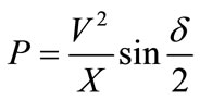 (1)
(1)
To understand the advantages of SVC, assume that an SVC is installed at the mid-point of the interconnecting line. In that case, the reactance of the SVC between the machine and infinite bus is X/2 ohms. Subsequently, the value of transmitted power can be calculated as
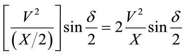 (2)
(2)
From Equation (2) it can be seen that the value of transmitted power is doubled i.e., from V2/X it goes to 2(V2/X). Accordingly, the transient stability level is also increased. This fact can also be validated by the transient stability equal area criterion with SVC and without SVCas shown in Figure 4.
Consider that Figure 4(a) is system without SVC and Figure 4(b) is system with SVC. Assume that both sys-
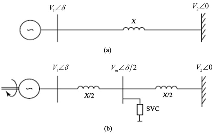
Figure 3. Simplified power systems (a) without SVC and (b)
with SVC [14].
tems are subjected to the same fault for the same period of time. Before the fault, each system transmits power PM and is operating at angle δ1 and δc1. During the fault, the transmitted power decreases significantly while the mechanical input power remains constant (PM). As consequence, the generator accelerates from δ1 to δ2 and δc1 to δc2 at which the fault clears. After fault clearing, the transmitted power exceeds the mechanical input power and the generator starts to decelerate. Nevertheless, their angle increases due to the kinetic energy stored in the rotors. At δ3 and δc3 the maximum rotor angle are reached when the decelerating energies that represented by areas ‘A2’and ‘Ac2’ become equal to the accelerating energies defined by areas ‘A1’ and ‘Ac1’. The maximum of transient stability limits is achieved at δ3 and δccrit. The areas of A margin and Ac margin represent the transient stability margin of the system.
From above description, it is evident that SVC is able to enhance transient stability limit. In addition, it is obvious that the transient stability is determined by power (P) against power angle (δ).
4. Experimental Setup
In order to make the power system become “Smarter”, this research considers small and simple system configuration with easier control and design as shown in Figure 5. The one-line system network is derived from [6] which presents successful islanding operation of distributed generation into the Smart Grid environment. However, this research only focuses on islanding examination and does not consider analyzing the system stability. Therefore, it is necessary to developed further under Smart Grid concept by simplifying the system in respect of control where Flexible AC Transmission System (FACTS) devices particularly Static VAR Compensator (SVC) is used. The typical network intends to evaluate the impact of distributed generation on Smart Grid’s steady state voltage profile and system stability or dynamic behavior, which is essential to establish an appropriate applied model.
Consider Smart Grid network consisting of a 132 kV; 50 Hz sub transmission system with maximum of short circuit levels 5000 MVA and 4000 MVA respectively. The grid feeds a 33 kV distribution system through a 132 kV/33 kV,  transformers with rated power equal to
  = 90 MVA, Short Circuit Voltage
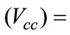 13.18%. In the system, two type of distributed generation technologies are considered as dispersed sources; named DG I and DG II. Each of them has rated power of 28.1 MVA and are separately coupled into the 11 kV bus through 33/11 kV transformers. The grid load in Smart Grid zone is 1 MW while the maximum load of the DGs is 23 MW.
The SVC, which letter on this is called Static VAR
 (a) (b)
Figure 4. Equal areas illustrating transient stability limit without SVC (a) and with SVC (b) [15].

Figure 5. Smart Grid topology network.
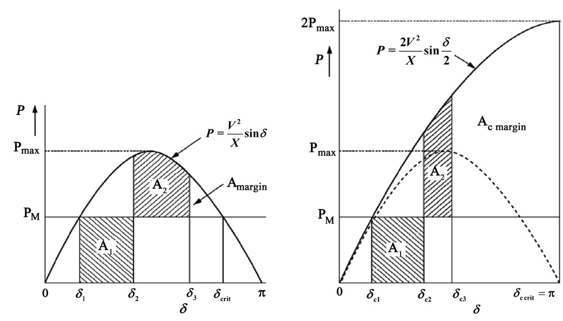
System (SVS), is installed in the grid to make the system become “smarter” particularly to maintain the system stability during the integration of distributed generation. Figure 6 shows the model of SVS controller frame used in this simulation [16]. It is based on IEEE model with the objective for voltage and power reactive control in the system. The SVS is installed at bus 2 at the mid-point of the system. The basic data parameters are given in Table 1.
Figure 6 shows that the measurement element (ElmSsc*) obtains active and reactive power, voltage, current and other signals from power system. The
Figure 6. SVS control frame [16].
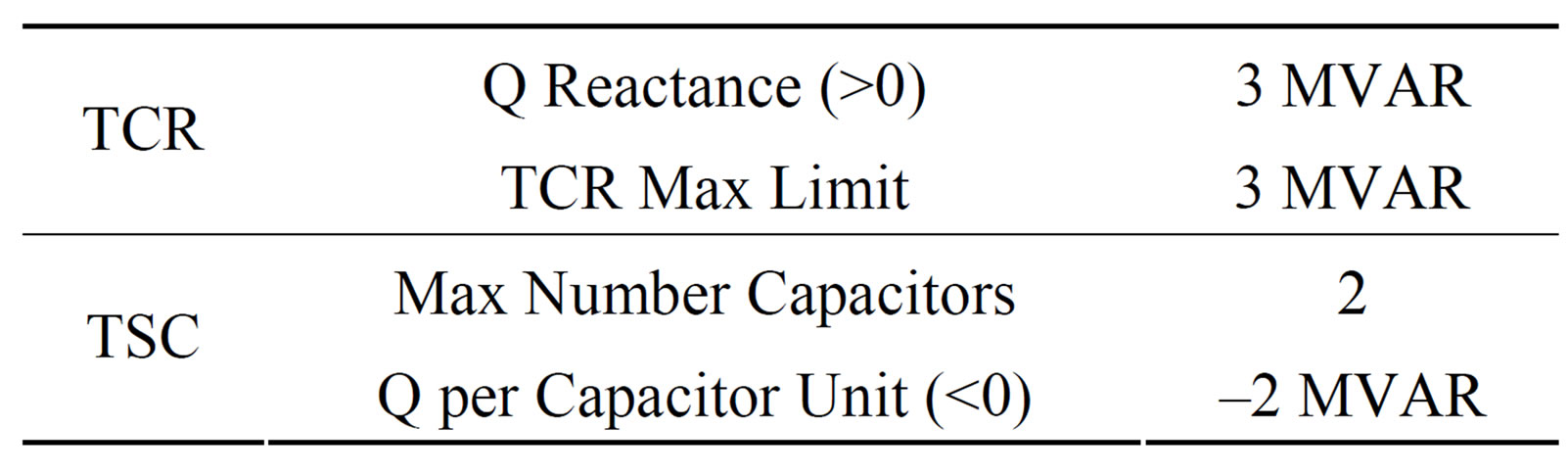
Table 1. Static VAR System parameters.
mea-surement system objective is to ensure that all the inputs are proportional for stable operation as required by the system. These signals then are transferred to SVS controller element (ElmSvc*) which has two distinct mode controls: voltage and reactive power control. The voltage control system aims to keep the voltage within acceptable limits, especially at Point of Common Coupling (PCC) since it is vital voltage regulation of the systems. To perform this, the voltage regulator processed all measured input variables and creates an output signal that is proportional to reactive-power compensation. The measured variables are compared with the voltage reference signal, and the error becomes an input variable forthe controller. The output of the controller creates a per-unit susceptance signal to reduce undesired signal error to zero in the steady state operation; afterward the signal is transferred to the gate-pulse generation. The output signal derived from voltage regulator is transferred to the gate-pulse generation which creates proper firing pulses for TCR-TSC of the SVC slot, subsequently the undesired susceptance signal is rectified and the desired susceptance output is available at SVC bus.
5. Case Studies
This section provides general overview of the case scenarios for the research and its assumption. In order to illustrate the impact types of distributed generation on Smart Grid, steady state voltage analysis and transient stability analysis have been performed. The considered scenarios are as follow:
Case 1: Steady state voltage profiles have been evaluated using a load flow Newton-Raphson Method to check the voltage pattern and possibly overloading.
Case 2: Transient stability analysis was performed particularly when DG I and DG II are coupled into Smart Grid. The parameters being measured are frequency, voltage and power angle.
Case 3: Transient stability analysis was performed particularly when fault occurs in the system. The parameters being measured are frequency, voltage and power angle.
Before observing the impact of DG on Smart Grid the following procedure was adapted to address the 3 cases presented above. In all cases, steady state profiles have been evaluated using a load flow Newton-Raphson procedure. The distributed generation is modeled in PQ and PV node. The system is assumed to be in very high demand and under balanced condition. The dynamic behavior of load is not considered.
Initially, during operation the voltage and frequency of the DG I is controlled by Smart Grid, thus the DG I at 11 kV bus is operated in PQ mode. Meanwhile, DG II operates independently in PV mode. For safety reason, normally DG should not operate in PV mode when it is connected to network. However, in this case study the operation mode of DG II is kept in PV mode when it is connected to the grid. This approach is intended to evaluate the reliability of connecting DGs to Smart Grid when DGs modeled as PV node. In all case studies, DG II is connected to the grid at t = 4 seconds by closing the Point of Common Coupling (PCC) in bus 7 and the intertie line between GT I and GT II. In addition, to avoid system collapse due to power reactive injection or absorption from distributed generation the SVS is operated in reactive power control mode (Q mode).
6. Experimental Result and Analysis
The following section presents the result and analysis done for the simulations. In all simulated case studies, the load flow calculation and initial system conditions have been performed successfully. At this stage, preliminary simulation shows that there was no error found in the system topology such as over voltage or under voltage and over load. The default information in this regard is shown in Figure 7" target="_self"> Figure 7.
6.1. Smart Grid Steady State Voltage Analysis (Case 1)
One of the main benefits from integration of distributed generation in electricity networks is an improvement of the steady state voltage profile of the system. However, voltage violation and fluctuation during the connection of distributed generation could happen and considerably influence the network transient stability. Therefore, the Power System Operators (PSO) must verify that in the worst situation, the networks steady state voltage variation is no greater than 5%. This section addresses the impact of distributed generation on Smart Grid steady state voltage.
Regarding Smart Grid steady state voltage profile before employing DG I and DG II, it is assumed that in all case studies the entire system bus voltage remain constant at 1 p.u. The considered maximum and minimum voltage variation is ±5% from nominal voltage. Thus, the results of steady state voltage profile obtained for all buses after employing DG I and DG II is presented in Table 2.
It can be seen from Table 2 that a voltage deviation in Smart Grid still occurs due to imbalance in reactive power generated by the DGs during the integration. However, large violations of voltages are not evident on all buses. The overall Smart Grid voltage remains within the allowable range between 0.95 p.u and 1.05 p.u, which is 0.996 p.u. From the result presented in Table 2 it appears that the bus 1 (SG zone) is not sensitive when DG I and DG II units are utilized in Smart Grid.
6.2. Smart Grid Transient Stability Analysis
The Smart Grid response following integration of distributed generation to the network steady state profile has been examined. It demonstrates that the Smart Grid steady state voltages profile is within acceptable limit between 0.95 p.u and 1.05 p.u. Nevertheless, this condition cannot guarantee the system remains stable if a fault occurs on the system. Therefore it is critical to examine the Smart Grid transient stability. The transient stability analysis investigates the system responses after distributed generation is integrated to Smart Grid and following fault occurrence. The considered indicator for stability study is determined by analyzing Smart Grid voltage magnitude, frequency and power angle.
6.2.1. Grid Connected Mode Stability Analysis (Case 2)
This section discusses the Smart Grid stability (Case 2) during integration of distributed generation or grid connected mode stability analysis. Figure 8 shows that by connecting DG II the voltage stability of Smart Grid at bus 132 kV changes slightly. However, the deviation remains in acceptable range and clearly shows that the voltage takes 5 seconds to stabilize after connecting to DG II. The presence of voltage instability in this case results from progressive rise in operating slip or speed of distributed generation to restore the power and synchronizing the system as illustrated in Figure 9. As a consequence, due to high rotor slip the reactive power demand by DG II is greatly increased and might cause further voltage instability if reactive power controller is not used. Therefore, during grid connected mode, the SVS is operated in Q mode to provide and regulate the reactive power.
Following voltage imbalance, further studies were carried out to analyze the frequency stability of Smart Grid. As illustrated in Figure 10, it can be seen that the frequency level increase slightly and occurs at switching point where DG units are integrated to Smart Grid.
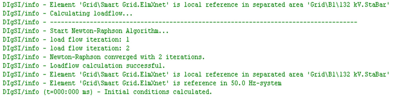
Figure 7. Information of initial load flow and system conditions.

Table 2. Overall Smart Grid voltage profile after employing distributed generation.
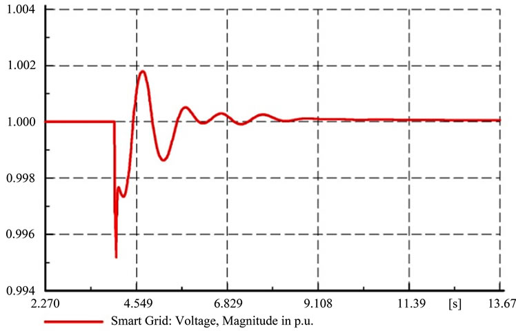
Figure 8. Smart Grid voltage magnitude in p.u during DGs integration.
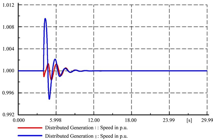
Figure 9. Distributed Generation speed in p.u during integration to Smart Grid.
However, the network succeeded to maintain new steady frequency after integrating with DGs. In this case, the frequency rises from 50 Hz to 50.03 Hz when the PCC was closed at t = 4 seconds. Figure 11 shows the range of frequency deviation, which is only 0.04 Hz and is no more than ±2 Hz from nominal 50 Hz. Therefore, this frequency variation is acceptable and most of end user can bear this change. The Grid Code requires that the system frequency must be controlled within the limits of 47.5 - 52 Hz in case the system frequency rises above the limit [17]. However, larger violation can result in network collapse which leads to blackout.
On the other hand, another indicator to asses Smart Grid transient stability during grid connected mode is the voltage angle stability. As can be seen from Figure 12, the integration of DGs unit causes change of voltage angle which forces the network to operate at a new operating point. In this case, the maximum deviation was at t = 4 seconds between 89.60 and 90.22 degrees. The amount of reactive power absorption or injection by DGs during interconnection determines a significant respond of power angle, voltage and frequency stability. If the system lacks sufficient reactive power, it could cause an under voltage. However, it can be seen that the network maintains the voltage angle back to its original structure after 5 seconds.
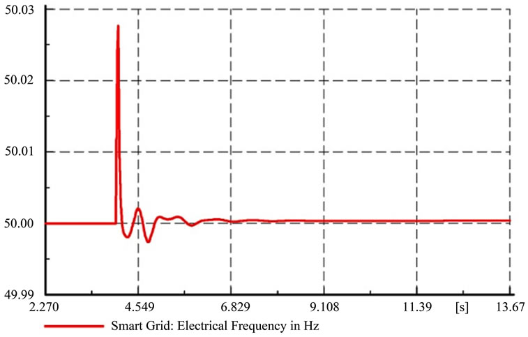
Figure 10. Smart Grid frequency during integration of DGs in Hz.

Figure 11. Smart Grid frequency total deviation during integration of DGs in Hz.

Figure 12. Smart Grid voltage angle during integration of DGs in degree.
6.2.2. Fault Stability Analysis (Case 3)
With the same network configuration and SVS connected, further Smart Grid stability is examined after the integration of DGs. The 200ms self-clearing 3 phase fault short circuit was applied at 15 seconds in the middle of transmission line connecting between Buses 2 and 3. The Smart Grid response during this fault is depicted in Figure 13. It can be seen that during the fault, the AC voltage plunges from 1.0 p.u to 0.988 p.u and it causes the electric torque to drop. Accordingly, the DG rotor speeds up and the reactive power absorption is greatly increased because of high rotor slip. However, due to fast dynamic power reactive support from the SVS, the Smart Grid voltage recovers within 2 seconds after the clearance of the fault and the system goes back to stable.
For the Smart Grid frequency stability response following the fault, Figure 14 indicates that during the fault, the system frequency plunges from 50 Hz to 49.997 Hz. Unfortunately, the post-fault frequency is slightly less than its nominal value between 49.998 Hz and 49.999 Hz. This phenomenon occurs as consequence of imbalance be-
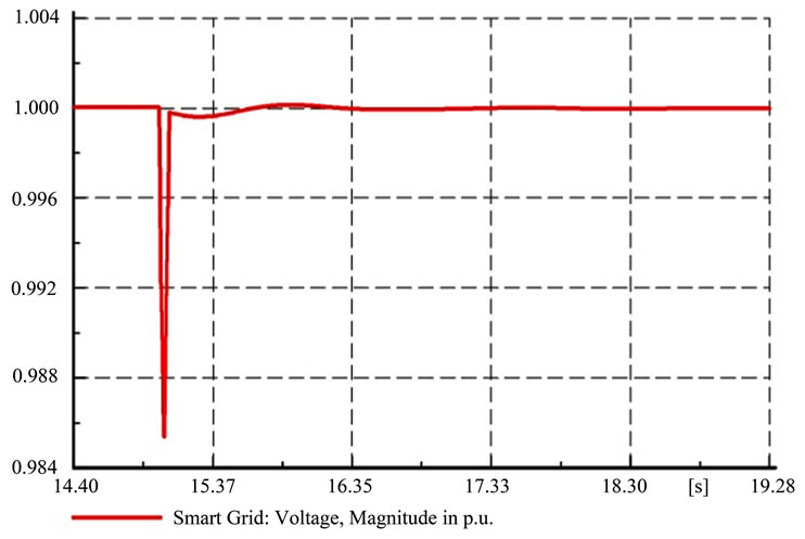
Figure 13. Smart Grid voltage responds during 3 phase fault in p.u.
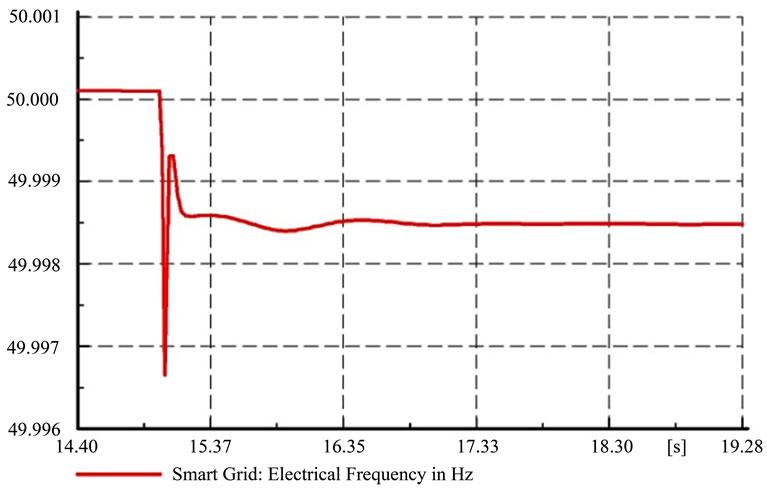
Figure 14. Smart Grid frequency responds during 3 phase fault in Hz.
tween the electromagnetic and the mechanical torque of DGs after the fault. However, it tends not to be of significant concern. Moreover, the rotor speed is gradually reduced and their equilibrium also restored gradually after the SVS has provide sufficient reactive power support. Thus, the post fault frequency level remains stable above 49.998 Hz.
On the other hand, as consequence of three phase short circuit fault, the Smart Grid voltage angle dips approaching to 89.30 degrees as depicted in Figure 15. This incidence leads to voltage drop as illustrated in Figure 13. In view of this, the change of the voltage angle will always correspond with the change of voltage and frequency limits. However, the use of SVC helps the system to maintain synchronism with the DGs during and post fault. As shown in Figure 15, the voltage angle regains to 90 degrees within 2 seconds. Thus new steady state value between DG and Smart Grid reaches.
7. Conclusions
This paper addresses the impact of distributed generation
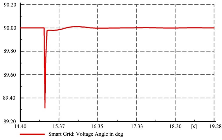
Figure 15. Smart Grid voltage angle during 3 phase fault in p.u.
on Smart Grid’s transient stability analysis. The steady state voltage during the integration of DG and transient stability of Smart Grid following self-clearing 3 phase fault have been examined.
Regarding steady state voltage behaviors, it is found that the integration of DG does not modify the performance of Smart Grid. It shows that the steady state voltage deviation is still within limits. Transient stability analysis however, shows that the utilization of SVC is able to maintain the voltage, frequency and voltage angle and remains in stability margin following the DG connection and fault. The simulation result clearly indicates that reactive power support is necessary when utilizing DG. This fact is confirmed through transient stability equal area criterion in Section 3 that the existence of SVC helps significantly the transient stability of the system. With proper control and installation of SVC in the system, it can provide voltage and power reactive support and with the increase in transmission capability transient stability margin increases. In addition, the feasibility of connecting DG in PV mode was also analyzed. It can be seen that the DG II is successfully integrated in Smart Grid while its operation is in PV mode; therefore the DG II is not switched in PQ mode operation during integration to the grid.
Finally, the results of this research shows that in particular term of stability and time recovery, a favorable comparison to reference [6] and [18], which takes more than 8 seconds to settle after islanding. Due to its capability for successful DG integration and a rapid recovery after fault, it is suitable to be examined as Smart Grid. However, further investigation for future work is still necessary; the scope of the research includes harmonic analysis, different FACTS controller and level of DG penetration.
8. Acknowledgements
The first author would like to acknowledge the Australian Development Scholarship (ADS) for providing the support essential to pursue his Master by Research at Victoria University, Melbourne, Australia.
REFERENCES
- T. Khoan and M. Vaziri, “Effects of Dispersed Generation (DG) on Distribution Systems,” IEEE in Power Engineering Society General Meeting, Sacramento, 16 June 2005, Vol. 3, pp. 2173-2178.
- R. A. Prata, “Impact of Distributed Generation Connection with Distribution Grids—Two Case-Studies,” IEEE in Power Engineering Society General Meeting, Montreal, Quebec, Vol. 19, 18-22 June 2006, p. 8.
- C.-I. Chai, W.-J. Lee, P. Fuangfoo, M. Williams and J. R. Liao, “System Impact Study for the Interconnection of Wind Generation and Utility System,” IEEE Transactions on Industry Applications, Vol. 41, No. 1, 2005, pp. 163-168. doi:10.1109/TIA.2004.841032
- F. Bastiao, P. Cruz and R. Fiteiro, “Impact of Distributed Generation on Distribution Networks,” Proceedings of the 5th International Conference on European Electricity Market, Lisboa, 28-30 May 2008, pp. 1-6. doi:10.1109/EEM.2008.4579049
- P. P. Barker and R. W. De Mello, “Determining the Impact of Distributed Generation on Power Systems. I. Radial Distribution Systems,” Proceedings of IEEE Power Engineering Society Summer Meeting, Seattle, Vol. 3, 16-20 July 2000, pp. 1645-1656. doi:10.1109/PESS.2000.868775
- S. P. Chowdhury, S. Chowdhury, C. F. Ten and P. A. Crossley, “Operation and Control of DG Based Power Island in Smart Grid Environment,” Proceedings of the 20th International Conference and Exhibition on Electricity Distribution - Part 1, Prague, 8-11 June 2009, pp. 1-5.
- A. A. Kumar, A. R. Massannagari, A. K. Srivastava and N. N. Schulz, “Impact of Biomass Based Distributed Generation on Electrical Grid,” Proceedings of Clean Technology Conference, Boston, 1-5 June 2008, pp. 222-225.
- N. A. Hidayatullah, Z. J. Paracha and A. Kalam, “Impacts of Distributed Generation on Smart Grid,” Proceedings of the International Conference of Electrical Energy and Industrial Electronic System, Malaysia, 7-8 December 2009, pp. 218-221.
- NIST Special Publication 1108, “NIST Framework and Roadmap for Smart Grid Interoperability Standard, Realease 1.0,” Office of the National Coordinator for Smart Grid Interoperability, National Institute of Standart and Technology, U.S Department of Commerce, January 2010.
- C. W. Potter , A. Archambault and K. Westrick, “Building a Smarter Smart Grid through better Renewable Energy Information,” Proceedings of IEEE/PES Power Systems Conference and Exposition, Seattle, Washington D. C., 15-18 March 2009, pp. 1-5.
- doi:10.1109/PSCE.2009.4840110
- N. G. Hingorani and L. Gyugyi, “Understanding FACTS: Concepts and Technology of Flexible AC Transmission Systems,” IEEE Press, New York, 2000, p. 452.
- K. R. Padiyar, “Facts Controllers in Power Transmission and Distribution,” New Age International Ltd. Publisher, New Delhi, 2009, p. 532.
- E. H. Watanabe, et al., “Flexible AC Transmission Systems,” Power Electronics Handbook, Elsevier Inc, 2007.
- R. M. Marthur and R. K. Varma, “Thyristor-Based FACTS Controllers for Electrical Transmission Systems,” IEEE Press and Wiley, New York, 2002, p. 493.
- R. S. Vedam and M. S. Sarma, “Power Quality VAR Compensation in Power Systems,” CRC Press, Boca Raton, 2009, p. 268.
- Dig-SILENT Power Factory Software 13.2.
- National Grid Electricity Transmission plc, “The Grid Code,” Issue 4, Revision 3, London, 2010.
- I. Vokony and A. Dan, “Examination of Smart Grids in Island Operation,” IEEE Bucharest Power Tech Conference, Bucharest, 2 June-28 July 2009, p. 1-7.