Smart Grid and Renewable Energy
Vol.1 No.3(2010), Article ID:3327,7 pages DOI:10.4236/sgre.2010.13020
Performance of a Wind-Diesel Hybrid Power System with STATCOM as a Reactive Power Compensator
![]()
1Centre for Energy Studies, Indian Institute of Technology Delhi, New Delhi, India; 2The Energy and Resource Institute Delhi, New Delhi, India.
Email: bitt1979@gmail.com
Received October 31st, 2010; revised November 25th, 2010; accepted November 30th, 2010
Keywords: Permanent-Magnet Induction Generator, Permanent-Magnet Synchronous Generator, Wind-Diesel Hybrid Power System
ABSTRACT
The paper deals with automatic reactive power control of an isolated wind-diesel hybrid power system. The power is generated by diesel engine and wind turbine as prime movers with electrical power conversion by permanent-magnet synchronous generator (PMSG) and permanent-magnet induction generator (PMIG) respectively. The mathematical model of the system developed is based on reactive power flow equations. The paper investigates the dynamic performance of the hybrid system for 1% step increase in reactive power load with 1% step increase in input wind power.
1. Introduction
Large interconnected power systems supply power to a locality at large for the optimum utilization of the power sources. Due to the non-availability of constraints on the right of way of providing additional transmission lines, sufficient funds, and rapid growth in load with the developments, the demand to provide power to all by large interconnected systems, especially in developing countries like India, does not met. On the other side, the gap between demand and supply is also increasing day by day that has introduced the use of renewable energy sources in addition to conventional energy sources. The sources such as solar, wind, mini/micro hydro, etc. have been introduced extensively as renewable energy sources which contribute to environmental protection also. These types of systems are called as isolated hybrid power systems. Normally diesel sets and wind turbines are connected with synchronous generators and induction generators (IGs), respectively [1,2]. There are several advantages of induction generators [3,4], but the performance of an induction generator is poor in terms of voltage regulation as it needs a magnetizing current from the source for the purpose of excitation which reduces both the power factor and efficiency of the induction generator [5]. The application of PMIG improves the power factor, voltage regulation and efficiency [5]. In PMIG, permanent-magnets are inserted in the conventional rotor of an induction generator. Various models and their applications [6-11] have been discussed to analyze the steady state performance of the PMIG. A d-q reference model for a PMIG has been described in [7]. The impedance model based on a conventional per phase equivalent circuit with per unit parameters has also been investigated [5,9,10] to know the performance of the PMIG. The reactive power flow equations based modeling of PMIG is very essential as it can easily be extended for the multi -machine systems. The PMSG is connected with the diesel set to avoid the need of automatic voltage regulator (AVR). The diesel generator acts as a local grid.
Various Flexible AC Transmission System (FACTS) devices, such as switched capacitors, SVC, and STATCOM, are available which can supply fast and continuous reactive power [12-16]. A switched capacitor bank is a good alternate to provide reactive power required by the induction generators in the grid connected systems. If there is an excess reactive power generated by the capacitors, it will be absorbed by the grid but in an isolated system, the load and the induction generators need the reactive power. Under varying condition, the mismatch between generation and consumption of reactive power may not lead to surplus of reactive power. The surplus of reactive power may cause high voltage spikes in the system, that can cause damage to the equipments connected and on at that instant. The switching capacitors may be an option if under any conditions of generation/load of the hybrid system, the problem of the surplus of reactive power may not arise. In general, a variable source of reactive power is needed to eliminate mismatch between generation and consumption of reactive power. The STATCOM [12] employs a voltage source inverter (VSC), which internally induces inductive or capacitive reactive power as required and is also advantageous [12] than that of SVC.
First the system state equations are derived from real and reactive power balance equations of the system. A voltage deviation signal is used by STATCOM controller to eliminate the reactive power mismatch in the system. The integral square error (ISE) criterion is used to evaluate the optimum gain settings of the controller parameters. Finally, the transient responses of the hybrid system are shown for 1% step increase in reactive power load with 1% step increase in input wind power.
2. Mathematical Modeling of the Wind-Diesel Hybrid Power System
A wind-diesel hybrid power system with STATCOM considered for study is shown in Figure 1. The real and reactive power balance equations of the system under steady state conditions are given by
 (1)
(1)
 (2)
(2)
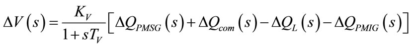
Due to disturbance in load reactive power , the system voltage can change that results an incremental change in reactive power of other components. The net reactive power surplus is
 , and it will change the system bus voltage which will govern by the following transfer function equation, see Equation (3) [17].
Where,  and
and  are the system gain and time constant. All the connected loads experience an increase with the increase in voltage due to load voltage characteristics as shown below:
 (4)
(4)
The composite loads can be expressed in exponential voltage form as
 (5)
(5)
The load voltage characteristics  can be found empirically as
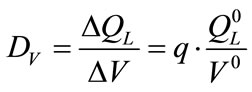 (6)
(6)
In Equation (3)  and
and  is the time constant of the system which is proportional to the ratio of electromagnetic energy stored in the winding to the reactive power absorbed by the system.
The small change in PMSG reactive power,  , connected with the diesel engines, in terms of state variables is given by:
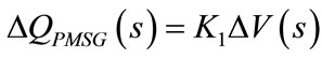 (7)
(7)
 (8)
(8)
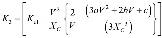
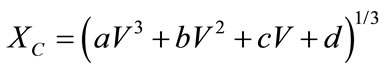
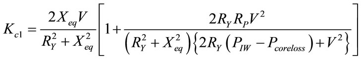
Similarly  can be expressed in terms of system state variables as given below. The equivalent circuit of the PMIG is shown in Figure 2. The reactive power absorbed,
  , in terms of generator terminal voltage, slip and generator parameters can be written as
 (9)
(9)
where
 (10)
(10)
 (11)
(11)
 (12)
(12)
and
 (13)
(13)
If  is infinity, then PMIG behaves like an IG. In Equation (12), the values of a, b, c and d are selected such that the effect of
  is equivalent to the permanent-magnets in providing reactive power at different voltages.
The STATCOM is based on a solid state synchronous voltage source that is analogous to an ideal synchronous
 (3)
(3)
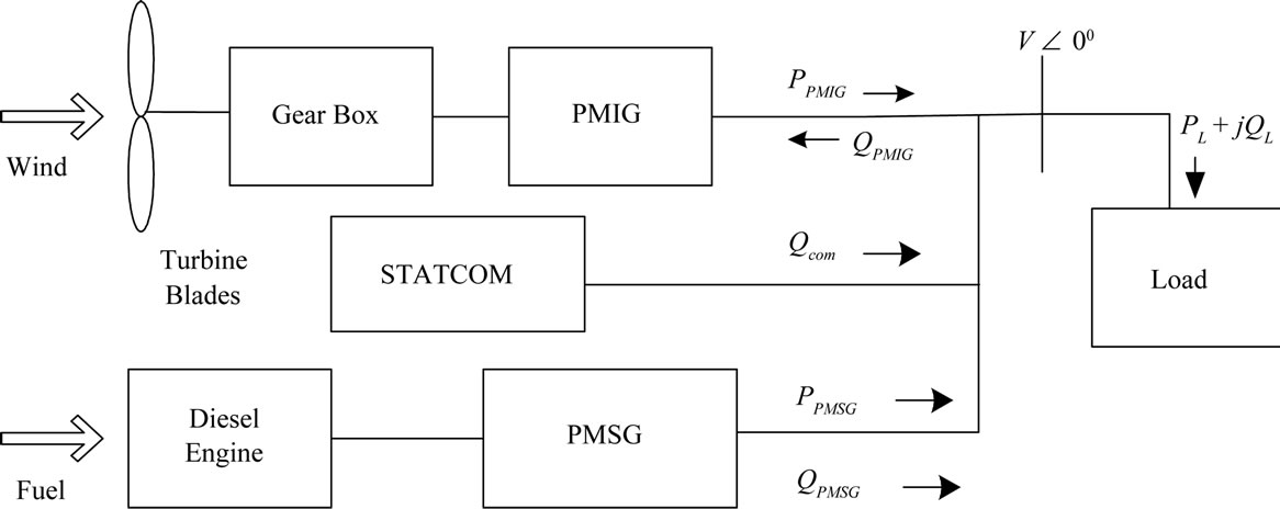
Figure 1. Single line diagram of the isolated wind-diesel hybrid power system.
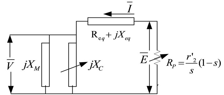
Figure 2. Equivalent Circuit of PMIG.
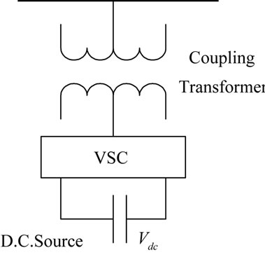
machine which generates a balanced set of three sinusoidal voltages, at the fundamental frequency, with rapidly controllable amplitude and phase angle. The configuration of a STATCOM is shown in Figure 3. It consists of a voltage source converter (VSC), a coupling transformer, and a D. C. capacitor as shown in Figure 3(a). The magnitude of the fundamental component of the converter output voltage is , where
  represent the voltage across the capacitor. The reactive power injection to the system bus has the form: [18].
 (14)
(14)
The system bus voltage is taken as reference voltage, therefore the angle,
 , is zero. Also
 , is negligible as
  represent the step down transformer admittance.
Therefore, considering the value of  and
and  to be zero, Equation (14) can be written as
 (15)
(15)
The flow of reactive power depends upon the variables  and
and , therefore for small perturbation the linearized STATCOM equation can be
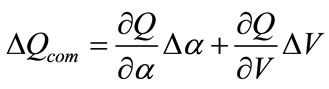 (16)
(16)
Substituting the value of partial derivatives from equation (15) in equation (16), we get
 (a)
(a)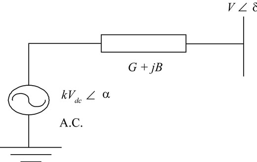 (b)
(b)
Figure 3. STATCOM (a) schematic diagram and (b) equivalent circuit.
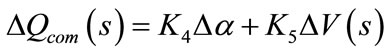 (17)
(17)
where,
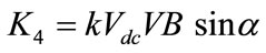 (18)
(18)
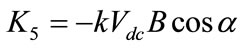 (19)
(19)
where,  and
and , is the pulse number of the inverter with modulation index unity [18].
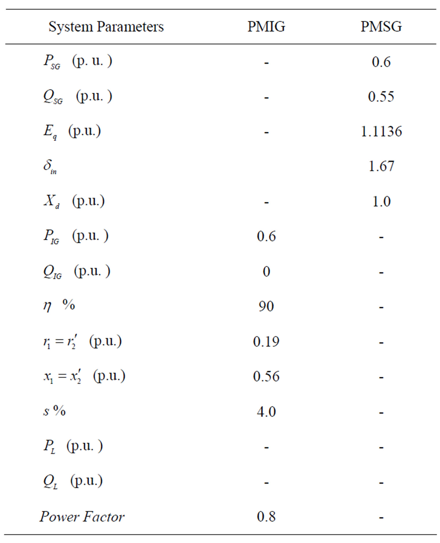
Using these equations, a simulation model of the system has been developed and the transfer function block diagram of the system is shown in Figure 4. All data of the system are given in the appendix.
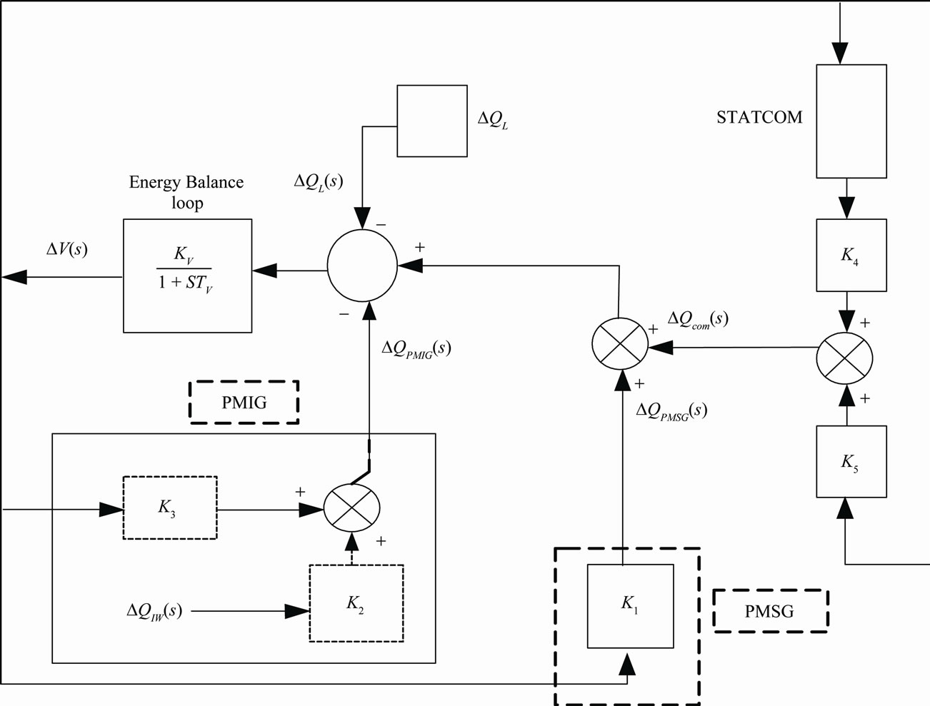
Figure 4. Transfer function block diagram of the wind-diesel hybrid power system.
3. Results and Discussions
The simulation results of the hybrid system have been carried out and the dynamic performance is presented in this section. The data of the hybrid power system are given in the Appendix. The performance index, , used in the parameter optimization for the isolated hybrid power system problem is based on of the ISE, which is given
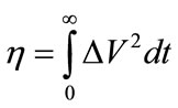 (20)
(20)
By focusing on the square of the error function, the performance index penalizes both positive and negative values of the error. Therefore, the minimization of performance index with respect to the known parameter will provide the best voltage performance of the system. The proportional and integral gains and
and of the STATCOM were optimized using Integral Square Error technique.
The proportional and integral gains, and
and of the STATCOM were optimized and the optimized values of
  and
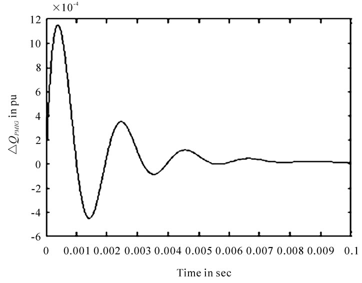
and were 7, and 1800, respectively. The transient responses of the wind-diesel hybrid power system for 1% step increase in reactive power load with 1% step increase in input wind power are shown in Figure 5.
It is observed from Figure 5 that initially as the load increases, the system voltage decreases. The decrease in voltage results in increase in the reactive power of the PMSG connected with the diesel set and STATCOM when PMIG is coupled with wind turbine. The decrease in voltage results in increase in reactive power of synchronous generator and STATCOM. The reactive power supplied by the PMSG and PMIG reduces as the system voltage deviation reduces as shown in Figures 5(b), (c). It has also been observed that the reactive power required by the load is finally fulfilled by STATCOM under steady state condition as shown in Figure 5(d).
4. Conclusions
The reactive power control of an isolated wind-diesel hybrid power system has been shown in this paper. A PMIG has been considered for the generation of electric power from wind turbine and PMSG is connected with the diesel set. STATCOM is used for providing variable reactive power required by the system. A complete dynamic model of the system has been derived to study the effect of load disturbances and input wind power disturbances. The dynamic performance of the system was
 (a)
(a)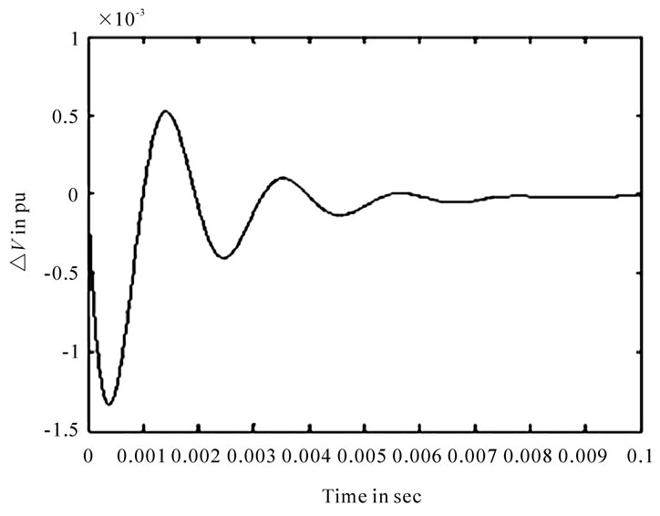 (b)
(b)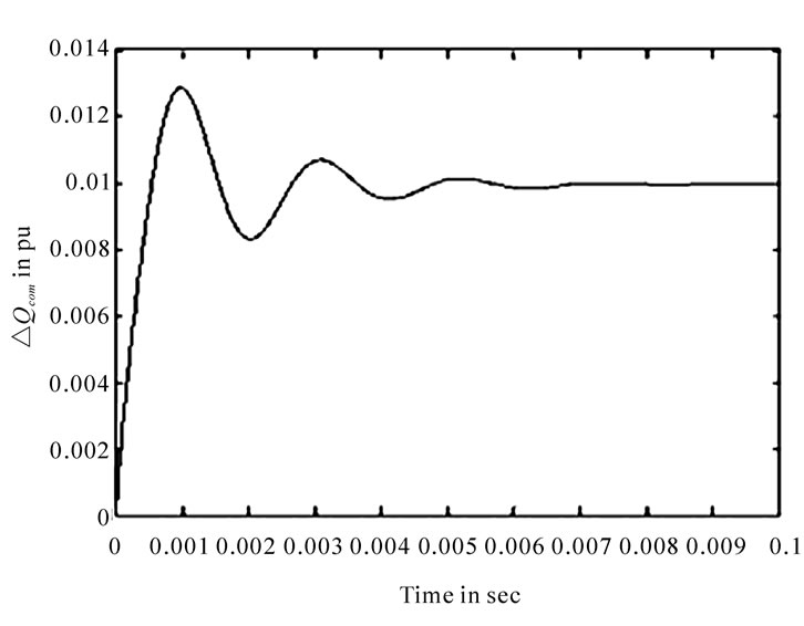 (a)
(a)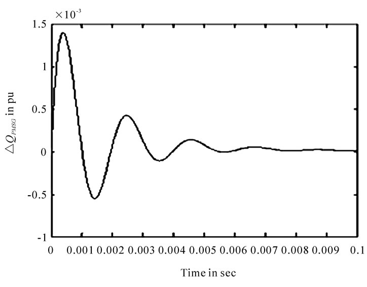 (b)
(b)
Figure 5. Transient responses of the wind-diesel system for 1% step increase in reactive power load with 1% step increase in input wind power, time vs (a) , (b)
, (b) , (c)
, (c) , and (d)
 .
.
investigated by optimizing the controller gains of the STATCOM using ISE technique. It has been observed that during dynamic condition the STATCOM eliminate the oscillations effectively with in 0.01 sec. caused by disturbances. As steady state condition reaches the STATCOM provides the additional reactive power required by the load. Some of the dynamic responses of the hybrid system have also been shown in the paper.
REFERENCES
- R. Hunter and G. Elliot, “Wind-Diesel Systems, a Guide to the Technology and Its Implementation,” University Press, Cambridge, 1994.
- H. Nacfaire, “Wind-Diesel and Wind Autonomous Energy Systems,” Elsevier Applied Science, London, 1989.
- A. A. F. A1-Ademi, “Load-Frequency Control of StandAlone Hybrid Power Systems Based on Renewable Energy Sources,” Ph. D Dissertation, Centre for Energy Studies, Indian Institute of Technology, Delhi, India, 1996.
- O. I. Elgerd, “Electric Energy System Theory: An Introduction,” Tata Mcgraw Hill, New Delhi, India, 1982, pp. 299-361.
- T. Fukami, K. Nakagawa, Y. Kanamaru and T. Miyamoto, “A Technique for the Steady-State Analysis of a GridConnected Permanent-Magnet Induction Generator,” IEEE Transaction on Energy Conversion, Vol. 19, No. 2, 2004, pp. 318-324.
- T. Fukami, K. Nakagawa, Y. Kanamaru and T. Miyamoto, “Performance Analysis of the Permanent-Magnet Induction Generator under Unbalanced Grid Voltages,” Translated from Denki Gakkai Ronbunshi, Vol. 126, No. 2, 2006, pp. 1126-1133.
- J. F. H. Douglas, “Characteristics of Induction Motors with Permanent-Magnet Excitation,” Trans AIEE (PAS), Vol. l78, 1959, pp. 221-225.
- B. Ackermann, “Single Phase Induction Motor with Permanent-Magnet Excitation,” IEEE Transaction on Magnetic, Vol. 36, No. 5, 2000, pp. 3530-3532.
- T. Fukami, K. Nakagawa, Y. Kanamaru and T. Miyamoto, “Effects of the Built-in Permanent Magnet Rotor on the Equivalent Circuit Parameters of a Permanent Magnet InDuction Generator,” IEEE Transaction on Energy Conversion, Vol. 22, No. 3, 2007, pp. 798-799.
- T. Fukami, K. Nakagawa, R. Hanaoka, S. Takata and T. Miyamoto, “Nonlinear Modeling of a Permanent-Magnet Induction Machine,” Transactions on Institute of Electrical Engineers of Japan, Vol. 122, No. 7, 2002, pp.752- 759.
- J. H. J. Potgieter, A. N. Lombard, R. J. Wang and M. J. Kamper, “Evaluation of Permanent-Magnet Excited InDuction Generator for Renewable Energy Applications.” http://research.ee.sun.ac.za/emr/files/u1/Paper29JHJPotgieter.pdf
- N. G. Hingorani and L. Gyugyi, “Understanding FACTs: Concepts and technology of Flexible AC Transmission Systems,” IEEE Power & Energy Society, New York, 2000.
- S. E. Haque, N. H. Malik and W. Shepherd, “Operation of a Fixed Capacitor Thyristor Controlled Reactor (Fc-Tcr) Power Factor Compensator,” IEEE Transaction on Power Apparatus and Systems, Vol. 104, No. 6, 1985, pp. 1385- 1390.
- A. E. Hammad, “Analysis of Power System Stability EnHancement by Static Var Compensators,” IEEE Transactions on Power System, Vol. 1, No. 4, 1986, pp. 222-227.
- E. G. Marra, et al., “Self-Excited Induction Generator Controlled by a VS-PWM Converter Providing High PowerFactor Current to a Single-Phase Grid,” Proceedings of Industrial Electronics Society Conferences, Aachen, 1998, pp. 703-708.
- S. C. Kuo and L. Wang, “Analysis of Voltage Control for a Self-Excited Induction Generator Using a CurrentControlled Voltage Source Inverter (CC-VSI),” IEEE Proceedings of Generation, Transmission and Distribution, Vol. 148, No. 5, 2001, pp. 431-438.
- R. C. Bansal, “Automatic Reactive Power Control of Isolated Wind-Diesel Hybrid Power Systems,” IEEE Transactions on Industrial Electronics, Vol. 53, No. 4, 2006, pp. 1116-1126.
- B. Kouadri and Y. Tahir, “Power Flow and Transient Stability Modeling of a 12-Pulse Statcom,” Journal of Cybernetic and Informatics, Vol. 7, 2008, pp. 9-25.
Nomenclature
 = Electro-magnetic energy stored in the PMIG.
 = Small change in the stored electromagnetic energy of PMIG.
 = Proportional and integral controller gain of the STATCOM regulator, respectively
 = Performance index.
 ,
, = Real and reactive power generated by wind turbine with PMIG
 ,
, = Real and reactive power generated by diesel set with synchronous generator.
 ,
,  = Real and reactive power of load demand.
 = Apparent power delivered by the IG and PMIG.
 = Reactive power generated by STATCOM.
 = Incremental change in the voltage.
 = Incremental change in the phase angle at a static synchronous compensator.
 = Equivalent resistance, equivalent reactance, and magnetizing reactance of the PMIG respecttively
 = Slip of PMIG
 = System terminal voltage.
 = Real and Imaginary parts of the E
 = Performance index q = Exponent in the reactive power load voltage characteristic
 ,
,  = Nominal values of the system voltage and reactive power of the load, respectively.
Appendix
The data of the wind-diesel hybrid power system are given below:
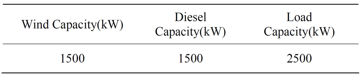
The data of the wind-diesel system are given as follows:
 ,
,  ,
,  ,
,  ,
, .
.