Smart Grid and Renewable Energy
Vol.4 No.2(2013), Article ID:31936,6 pages DOI:10.4236/sgre.2013.42020
Uniformly Illuminated Efficient Daylighting System
![]()
Department of Information and Communication Engineering, Myongji University, Yongin 449-728, South Korea.
Email: irfan@mju.ac.kr, sshin@mju.ac.kr
Copyright © 2013 Irfan Ullah, Seoyong Shin. This is an open access article distributed under the Creative Commons Attribution License, which permits unrestricted use, distribution, and reproduction in any medium, provided the original work is properly cited.
Received September 10th, 2012; revised January 15th, 2013; accepted January 22nd, 2013
Keywords: Uniform Illumination; Daylighting System; Optical Fiber; Solar Concentrator
ABSTRACT
Different approaches have been introduced for the daylighting system to reduce energy consumption, but they were not populated due to complex, high cost, and insufficient designs. There has been a recent problem in achieving uniform distribution of sunlight at a destination deep inside the building. Therefore, we propose a system to achieve high illumination by illuminating the surface of the absorber (optical fibers) uniformly. To capture sunlight, parabolic reflector and Fresnel lens are used. Different reflectors and lenses are considered, compared, and investigated to direct uniform light, which solves the heat problem, into the optical fibers. In addition, this study includes comparison between fiber-based daylighting systems. The proposed system has been verified through simulation and experimental results.
1. Introduction
By developing a suitable and more efficient daylight collecting and distributing system will lead us to a solution of the energy problem which is becoming more serious. Natural light is the requirement of our needs. There has been a research that sunlight has positive effects on the human body. It can be used to reduce seasonal affective disorder and other illnesses [1]. Daylighting system gives the reduction in power consumption and makes the cost at one time. It was not progressed due to less efficiency and poor design. In the sense of implementing the system at low cost, different methods have been introduced, but since the system was inefficient, it was difficult for it to be applied to all different kinds of building structures. Mostly, daylighting systems have some problems like: low accuracy in hardware designing, installing, and routing. There is a need of the best design that has high efficiency and simple architecture. Different solar light transport systems have been demonstrated using light pipes, prisms, and optical fibers [2-4]. Available fiber based system is the Himawari solar lighting system [4]. It has two series of models with the different number of lenses and optical fibers. The system contains quartzglass optical fibers that make the system very high cost. The recent requirement is to get high illumination that is not present in these models due to the limited number of optical fibers and size of collecting system. It contains the outdoor collecting system, which has small illuminated surface area. Therefore, a low illumination is achieved at the indoor unit, which has small surface area. Furthermore, the distribution of uniform light is becoming a very critical issue in the solid-state lighting. On the other hand, this issue is more serious in the daylighting system. In [5], a solar lighting and energy system has been presented. They introduced a fiber-based system to use solar light spectrum for lighting and energy. Our proposed system is also better for solar energy systems to direct uniform light on the solar cells to produce the same and large amount of energy from each cell, because only required light will be directed on the solar cells. Thus, our proposed system can help to produce an efficient solar energy system. Our current research and development show an improvement in the illumination of the optical fiber-based system. This study will focus on uniform distribution of the light. Therefore, transmission of uniform sunlight is possible deep inside the building areas like: store rooms, basement, room without any window, and different floor areas. Furthermore, different lenses and reflectors are investigated and implemented to achieve accuracy.
2. System Architecture
Size of the system is a very critical issue in the daylighting system. In order to install it over different free regions (e.g. roof) of the building, it should occupy a small area with effective output and adopt surrounding environment according to the required size. The size of indoor and outdoor modules is selected according to the required range of illumination. Normally, a large surface area is preferred to capture more light. It is tried to make the size small of the indoor apparatus as compared to the outdoor apparatus to deliver light at a deep inside the building. The light collecting system must capture a large amount of sunlight and focus it over the small area. To achieve this goal, the system is presented using optical fibers, lenses, and reflectors. A sun tracking module is installed to achieve direct light all times of the day, and the light collecting module is interconnected with it. There has been a research using Fresnel lens, but effective results were not achieved due to less efficient hardware designing. Fresnel lens has various advantages like lowcost, less affective from dust, easiness to install, and fewer hardware components. If we compare the surface area of the Fresnel lens and parabolic reflector, it will be concluded that parabolic reflector has more surface area than Fresnel lens with the same diameter. Therefore, more light can be captured using parabolic reflector. Parabolic reflector is used due to some features (e.g., easiness in manufacturing) as compared to other reflectors. In both cases, a second component is necessary in order to get the collimated light. It can also be easily converged or diverged at a certain angle. It was not under discussion in all previous systems to distribute sunlight uniformly on the surface of the absorber. They also tried to make their systems using different modules, but they could not achieve better performance due to lake of the simulation. Therefore, the purpose of this study is to achieve uniform daylight at the destination. In case of non-uniform, each optical fiber will have different amounts of light. Therefore, light will not be uniformly distributed over the different regions of the building, and the heat issue will be produced in case of high illumination. To solve this problem, accurate size and placement of components are mandatory. Previously, sunlight collecting systems were developed using different types of primary and secondary reflectors. In some cases, more than two reflectors were utilized to illuminate the absorber; however, the system becomes costly by increasing the amount of reflectors. A system was also presented that had similar reflectors, and they were moved according to the position of sun. Generally, it is tried to make the system with fewer numbers of modules for manufacturing and installing purposes.
In case of reflectors, diameter of the secondary reflector must be same as the diameter of the absorber to achieve uniform and collimated light. If we use secondary circular reflector, it does not produce collimated light and surface of the absorber remains non-uniform. Results show that only secondary parabolic reflector gives collimated and uniform light. Therefore, it is concluded that primary parabolic reflector with secondary parabolic reflector is a good combination for better performance. In case of Fresnel lens, plano-concave lens is used to produce collimated light and to illuminate the surface of the absorber uniformly. If only a Fresnel lens is used in the system, collimated light can not be produced. The diameter of the concave region, in the plano-concave lens, should be same as the diameter of the absorber to illuminate the absorber equally. Therefore, it is concluded that Fresnel lens as a concentrator with plano-concave lens is a good combination. Furthermore, each material has its own properties of reflectance and transmittance. Surface reflectivity of aluminum and silver are 92% and 96% for solar light, respectively [6], and a lens can transmit light up-to 92% [7].
Optical fibers have many advantages in the daylighting system, including highly acceptable for wiring and routing purposes in the building and the best source for the transmission of light from one place to another. The cost problem of using optical fibers is eliminated by introducing plastic optical fiber (POF) for most of the transmitting part. POF has a big core diameter to transmit a large amount of light by efficient total internal reflection. Distribution of light is an important issue in the solid-state lighting. In our case, we have a light source (optical fibers) of small size with high beam of light. Different lenses and reflectors can be used to distribute uniform light over a certain region at the destination. We can divide optical fibers in every region by considering the required light in that region. The amount of optical fibers depends on the size of the concentrator. If we want to illuminate a big area, we shall use a big concentrator. In order to investigate the efficiency of the system, we have done simulation. There is a compromise between size and efficiency of the Fresnel lens. If we increase the size of the Fresnel lens having a constant pitch, we get less efficiency due to blockage of the light. The Fresnel lens with a constant pitch of 0.5 mm is used. If we increase the diameter of the parabolic reflector, we shall achieve high efficiency due to the large surface area. Finally, it is concluded that parabolic reflector gives better efficiency, and Fresnel lens gives good performance with low cost.
3. Solar Concentrator Design
A concave parabolic reflector is used to concentrate light on the small area, and a convex parabolic reflector is used to direct collimated light on the surface of the absorber. Reflectors having less f-ratios and large aperture areas are used to collect more light. To achieve collimated light, both reflectors have the same f-ratio. A bundle of fifty four optical fibers is utilized to get high illumination and to reduce heat effect. Silica optical fiber (SOF) is mounted before POF. In order to reduce losses due to the air gap between them, index matching jell is applied. A parabolic reflector is designed by
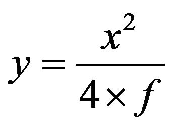 (1)
(1)
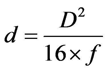 (2)
(2)
 (3)
(3)
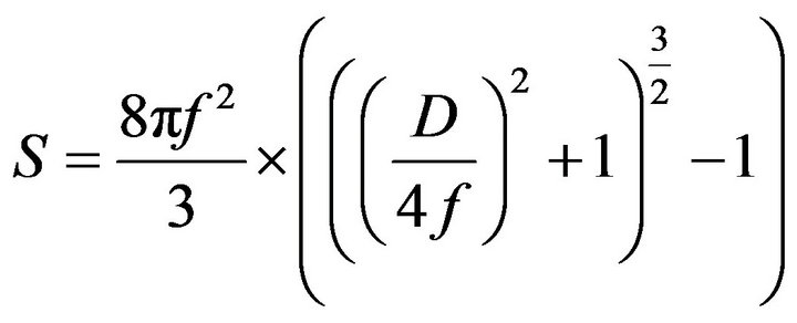 (4)
(4)
In Equation (1), y is value on vertical axis, x is value on horizontal axis, and f is the focal length. In Equation (2), D is the diameter, and d is the depth. In Equation (3), A is the area of aperture, and N is the focal number ( ). In Equation (4), S is the surface area of the parabolic reflector. Primary and secondary parabolic reflectors have surface areas of 87830.37 mm2 and 162.16 mm2. The diameter of the SOF and POF are 1.8 mm and 2 mm, respectively. The bundle of POFs at the destination has a surface area of 216.42 mm2. It is noted that the input surface area is about 371 times larger than the output surface area. Figure 1(a) shows that light is focused from a large area to a small area using reflectors. In Figure 1(b), we show that direct light is focused using a Fresnel lens and distributed on the surface of the absorber using a plano-concave lens. Similar designs for real experiment and software simulation were developed to achieve high accuracy. Therefore, losses in the simulation and real experiments were considered similar.
Here, we shall discuss three approaches using secondary circular reflector, secondary parabolic reflector, and lenses. Circular reflector is used to illuminate the surface uniformly, as shown in Figure 2(a). Direct ray has an angle α, which is 64 degrees, on the surface of the primary parabolic reflector with the horizontal axis. After that, it is reflected from the surface of the secondary reflector at a certain angle. We tried both patterns like: rays do not have a focal point and when they have a focal point. However, rays are not uniform in both cases. A large amount of rays are reflected at the center, but there are fewer rays at the ends. As a result, heat is maximized at the center. Secondary parabolic reflector gives uniform light at the surface of the absorber.
Secondary parabolic reflector has a radius r, depth a, focal length f2. Primary parabolic reflector has a focal length f1 and focal point F. It can be seen that focal points of both parabolic reflectors are at the same point. We can determine diameter and focal point of the convex reflector from the triangle as shown in Figure 2(b). If we know the focal point, the diameter will be calculated. If
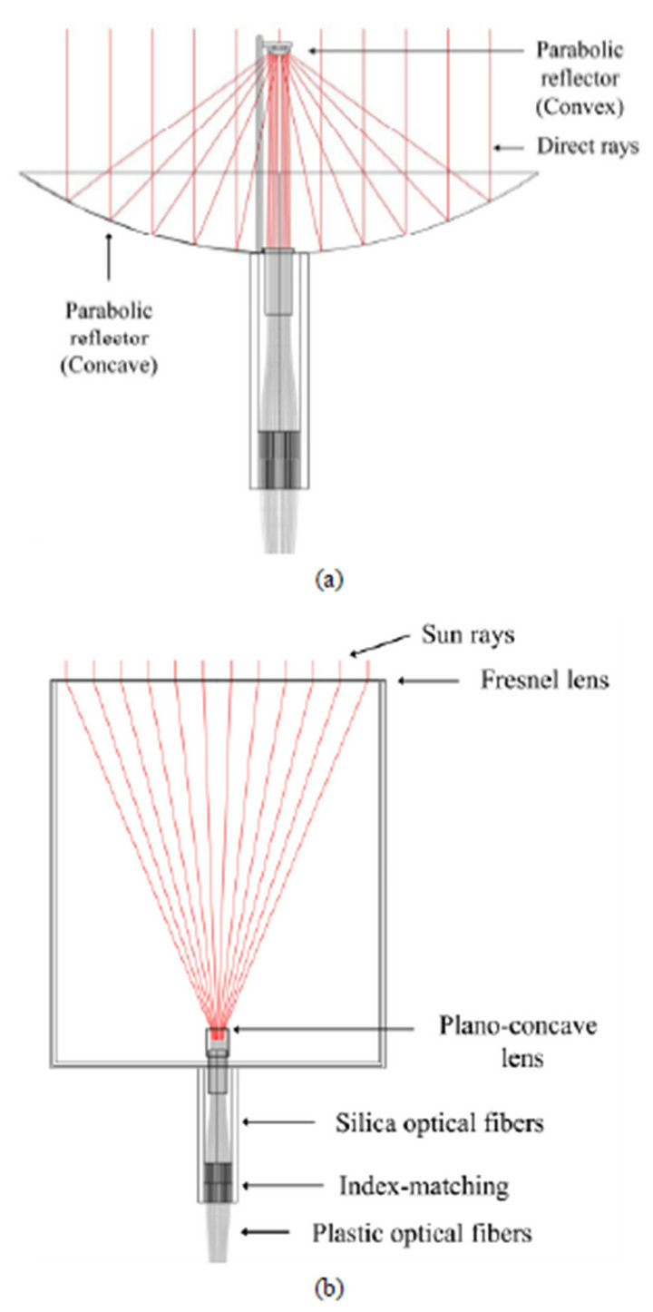
Figure 1. Structure of the system using (a) reflectors and (b) lenses.
we know the diameter, the focal point will be calculated. Therefore, placement of the secondary parabolic reflector is based on the focal point of the primary reflector. From these relationships, values of all parameters can be calculated. Previously, Fresnel lens based system has been already presented, but there is a lake of uniform distribution of light. Also, we want to compare three approaches to get the best design. In Figure 2(c), the design using lenses is described to show placement and positions of lenses.
4. Simulation Results
LightTools® was used to verify the proposed system. We have generated real time virtual environment in the simulation by designing each part and considering almost each loss. Source, receiver, reflectors, lenses, bending fibers, index-matching, and other hardware components
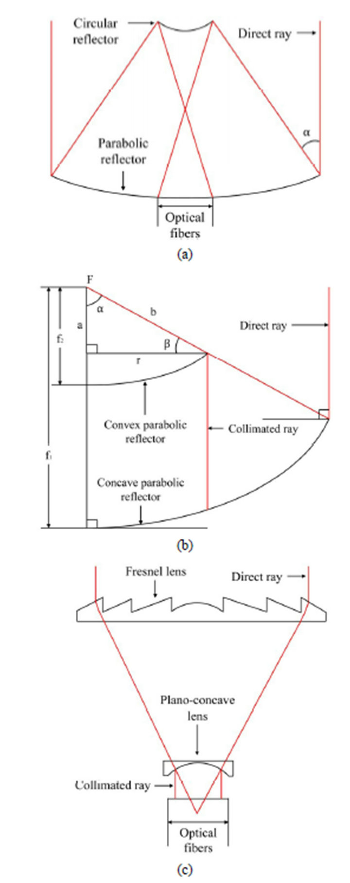
Figure 2. Configuration of the system using (a) secondary circular reflector; (b) parabolic reflectors; and (c) lenses.
are designed in the software. Bending fibers and their losses are considered in the simulation in order to check overall losses. Different refractive indices, reflection coefficients, and transmission coefficients are considered for each material. To see the actual losses, a light source is developed that has a spectrum similar to the sunlight. We also measured the heat effect on the optical fibers that can be estimated from the illuminance charts. Direction cosines of rays have been determined by the ray tracing method. Light rays after reflection from secondary parabolic reflector become perpendicular to the surface of the absorber. For Fresnel lens, rays after passing from the plano-concave lens become perpendicular to the surface of the absorber. Therefore, required lens can be easily designed according to the diameter of the absorber. Simulation is performed step by step from the initial stage to the end by examining the difference between results. Firstly, we considered a circular reflector to get collimated light, but it did not give an equal distribution of the light due to unparalleled rays. Thus, uniform light can’t be achieved using circular reflector. In order to achieve collimated light, a convex parabolic reflector is the best choice. The output results, considering the losses due to bending of optical fibers, can be easily seen in Figure 3. A light source is created in the simulation that transmits direct rays and produces uniform illuminance on the collecting system. A very large number of rays are transmitted to check the results with high resolution. The length of optical fibers in the simulation is considered same as that of the real time hardware. To reduce spacing between optical fibers, they are arranged in a circular shape. In the bundle of optical fibers, we tried to make the region empty, which has shadow due to any mechanical component.
In Figure 3(a), we show 2D illuminance, 3D illuminance, and rays scattered charts for secondary circular reflector. In this case, the numbers of rays are different in each fiber. Therefore, some optical fibers have high illuminance, but some optical fibers have low illuminance due to unparalleled reflection of rays from the surface of the circular reflector. In Figure 3(b), we illustrate illuminance charts using secondary parabolic reflector, where uniform distribution of light is attained. The surface is uniformly illuminated and high illuminetion is achieved in the bundle of optical fibers. There are two empty regions due to the shadow of the supporting rod and secondary reflector. In order to make it small, we used a very thin rod and a very small secondary reflector. In Figure 3(c), it is shown that all optical fibers have the same amount of rays using lenses. Here, we see that rays are collimated in this case; thus, uniform illumination is achieved. Fresnel lens is designed from the required diameter and focal length. It can be controlled by varying the groove pitch. It can also be designed by varying the groove depth, having a constant draft angle. Fresnel lens has a big advantage of long life time, and it is better for the system to implement, which is the requirement of lighting industry. A Fresnel lens is designed by
 (5)
(5)
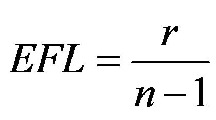
where EFL is the effective focal length, r is the radius, and n is the refractive index of the material, which has a value of 1.494.
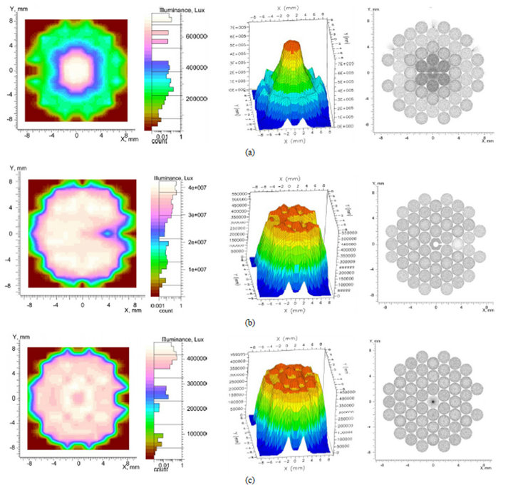
Figure 3. 2D illuminance, 3D illuminance, and rays scattered charts using (a) secondary circular reflector (b) secondary parabolic reflector, and (c) lenses.
5. Experimental Results
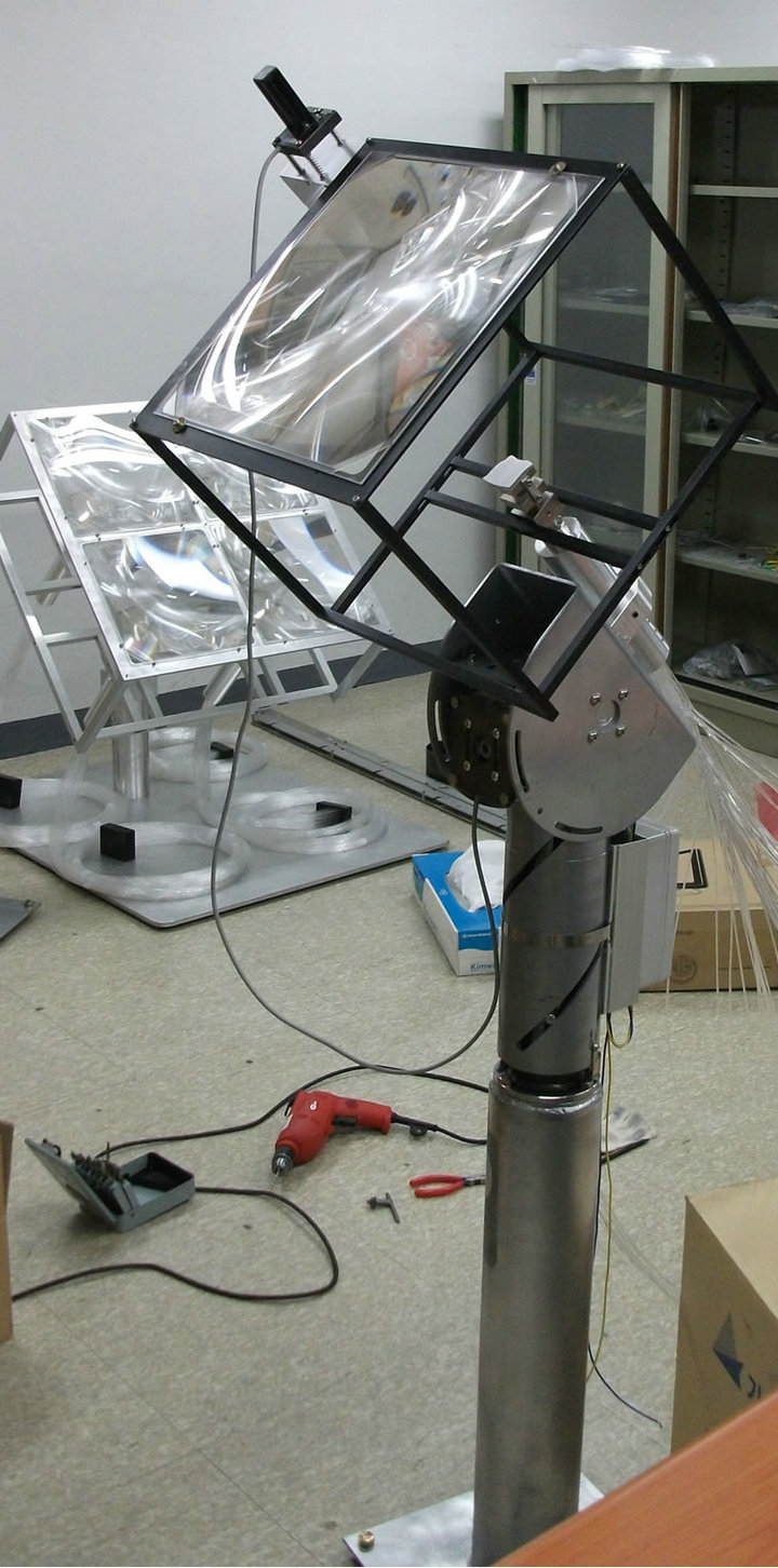
The system contains sun tracking, light collecting, light transmission, and light distributing modules. Experimental setup of the system using reflectors and lenses is shown in Figures 4(a) and (b). Three presented designs were established separately. The illuminance is measured in sunny and cloudy weather conditions at different times of the day. Experiments have shown that the proposed daylighting system can illuminate the required region uniformly. Uniform illumination using parabolic reflectors and lenses is shown in Figures 4(c), and Figure 4(d) shows the output illumination using secondary circular reflector that is not uniform. Therefore, the proposed system is acceptable for real implementation. Finally, it is concluded that both approaches using parabolic reflectors and lenses give high illuminance, because the light is distributed uniformly in both cases. Measurements of different parameters are illustrated in Table 1. Average input illuminance and output illuminance, which is measured at the end side of the fiber bundle, are mentioned in Table 2. Currently, the system is in working state. It has been installed at the university building to illuminate the room during the daytime.
6. Conclusions
As a result of the proposed system, a specific area of the building can be completely illuminated. Two efficient approaches have been presented. The study also demon-
 (a)
(a)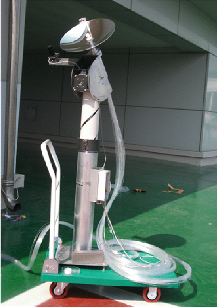 (b)
(b)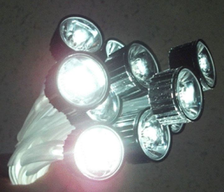 (c)
(c)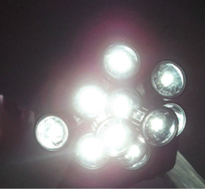 (d)
(d)
Figure 4. Hardware schematic using (a) reflectors and (b) lenses. Experimental results showing (c) uniformly illumination and (d) non-uniformly illumination.
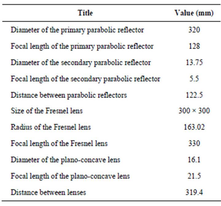
Table 1. Measurements of different parameters.
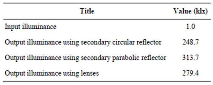
Table 2. Illuminance from simulation.
strates that more sunlight can be guided into optical fibers using a large sunlight collecting system. Finally, it is concluded that illuminance of more than 500 lx can be delivered uniformly into the building. A practical daylighting system has been explained and verified by real experiments and simulations.
7. Acknowledgements
This research was supported by Basic Science Research Program through the National Research Foundation of Korea (NRF) funded by the Ministry of Education, Science and Technology (2010-0012926).
REFERENCES
- A. Dunne, “Some Effects of the Quality of Light on Health,” Journal of Orthomolecular Medicine, Vol. 4, No. 4, 1989, pp. 229-232.
- I. Ullah and S. Shin, “Development of Optical FiberBased Daylighting System with Uniform Illumination,” Journal of the Optical Society of Korea, Vol. 16, No. 3, 2012, pp. 247-255. doi:10.3807/JOSK.2012.16.3.247
- I. Ullah and S. Shin, “Development of Optical FiberBased Daylighting System with Collimated Illumination,” Proceedings of the 2012 17th Opto-Electronics and Communications Conference (OECC), Busan, 2-6 July 2012, pp. 596-597.
- V. E. Gilmore, “Sun Flower over Tokyo,” Popular Science, Bonnier Corporation, New York, 1988.
- C. Tsuei, W. Sun and C. Kuo, “Hybrid Sunlight/LED Illumination and Renewable Solar Energy Saving Concepts for Indoor Lighting,” Optics Express, Vol. 18, No. S4, 2010, pp. A640-A653. doi:10.1364/OE.18.00A640
- P. Nostell, A. Roos and B. Karlsson, “Ageing of Solar Booster Reflector Materials,” Solar Energy Materials and Solar Cells, Vol. 54, No. 1-4, 1998, pp. 235-246. doi:10.1016/S0927-0248(98)00075-0
- H. Abdul-Rahman and C. Wang, “Limitations in Current Day Lighting Related Solar Concentration Devices: A Critical Review,” International Journal of the Physical Sciences, Vol. 5, No. 18, 2010, pp. 2730-2756.