Energy and Power Engineering
Vol. 4 No. 2 (2012) , Article ID: 18029 , 7 pages DOI:10.4236/epe.2012.42012
Thermal Modeling of a Novel Heated Tip Injector for Otto Cycle Engines Powered by Ethanol*
1Continental Brasil Indústria Automotiva Ltda, Powertrain Engine Systems, Salto, Brazil
2SISEA, Escola Politécnica, University of São Paulo, São Paulo, Brazil
Email: #jrsimoes@usp.br
Received November 24, 2011; revised December 22, 2011; accepted January 30, 2012
Keywords: Ethanol; Cold-Start System; Electromagnetic Heating; Heated Fuel Injector
ABSTRACT
This work presents a thermal modeling of a new cold-start system technology designed for Otto cycle combustion based on the electromagnetic heating principle. Firstly, the paper presents a state-of-the-art review and presents the context of automobile industry where heated injectors are necessary. The novel method of electromagnetic heating principle to solve the cold-start problem is still in the development phase and it enables engine starting at low temperatures in vehicles powered by ethanol or flex-fuel vehicles (FFV). This new system technology should be available as an alternative to replace the existing system. Currently, the cold-start system uses an auxiliary gasoline tank, which brings some inconvenience for the user. Secondly, the aim was also to create a physical model that takes into consideration all the parameters involved on the heating process such as power heating and average heat transfer coefficient. The study is based on the lumped system theory to model the ethanol heating process. From the analysis, two ordinary differential equations arise, which allowed an analytical solution. Particularly, an ethanol heating curve inside the injector was obtained, an important parameter in the process. Comparison with experimental data from other authors is also provided. Finally, a sensitivity analysis of controlling parameters such as heating power and heat transfer coefficient variation. The paper is concluded with suggestions for further studies.
1. Introduction
The introduction of vehicles powered by ethanol engines in the Brazilian market, during the late 1970s, faced a big issue: the cold-start at low temperatures. Ethanol fuel powered engines eventually show some ignition hurdles at cold-start and need an auxiliary gasoline tank to aid when exposed to low environmental temperatures (less than 15˚C). Regular gasoline from the auxiliary fuel tank is injected first to have the engine started off and then, the system switches to ethanol.
However, this usual method has shown some inconvenience to the driver, such as: 1) the periodic need to check the gasoline level and to refuel the auxiliary tank; 2) the due term for the amount of gasoline when the system is not used for a long period of time; 3) obstructing the system and causing the consequent failure in its working; 4) the risk of explosion in case of accidents; and, finally 5) the potential difficulty to meet the upcoming domestic emission legislation that shall be enforced in the next years, particularly related to cold-start.
Because of these problems, and with the need to improve the cold-start issue, it became necessary to develop a system able to aid vehicle cold-start, which is only ethanol powered at the minimum temperature of –5˚C, with no injection of any additional gasoline.
The ethanol has a low vapor pressure and a high flash point when compared to the gasoline, which makes it difficult to evaporate under certain conditions of low temperature. Therefore, ethanol needs some external energy source in order to make it able to ignite and to start the combustion. The present study proposed a solution based on heating up the ethanol fuel just before being injected by the principle of electromagnetism (induction).
The work aimed to model a heated injector induction using the theory of lumped heated systems in order to create a physical model that considers the most relevant parameters to the process of heating the ethanol inside the injector. In order to verify the accuracy of the approach it was performed some tests in fuel samples of heated injectors assembled in a real engine located in a cold chamber. The experiments analyzed the process, such as needed time for fuel pre-heating, needed heating power, and the indirectly measured average coefficient of heat transfer were compared to the results obtained by the modeling.
In the end of the study, the degree of accuracy of the modeling in face of the tests were verified and a reasonably good agreement was achieved nevertheless the rather simple lumped system approach. The present study can be used as a useful tool to guide the development of this technology to reduce time and cost in the construction of the samples, besides aiding the development of the vehicular electrical architecture, since it considers the needed power and its corresponding demand of energy for the electrical system of the vehicle stored in the batteries needed to start off the engine. The modeling parameters can be implemented in the algorithm of the engine management system software in order to estimate the ethanol temperature inside the injector and the time needed to pre-heat it prior injecting it in the cold engine and successfully have it started.
2. Cold-Start Systems Evolution and Technologies
In this section it is discussed the brief history of cold starting system used in the Brazilian automotive market and the introduction of the Flexible-Fuel Vehicles (FFV).
2.1. Cold-Start by Using an Auxiliary Gasoline Tank
Nowadays, all the vehicles fuelled with ethanol and or flex-fuel technology manufactured in Brazil are equipped with an auxiliary cold-start system with the following main components: a small gasoline sub-tank, an auxiliary pump, a 2- or 3-way solenoid valve, and a tubing system to take the gasoline to an auxiliary atomizing nozzle, usually positioned in the throttle body or in the intake manifold. That auxiliary cold-start system has been widely used by the manufacturers of Brazilian vehicles since the mid-1980s. After the introduction of vehicles with flex-fuel technology, since 2003 their use has been extended and failures caused by incorrect operation have become a great source of worry among the manufacturers of the vehicles that supply the Brazilian market.
During the mid-1980s, the vehicles using ethanol were not equipped yet with engine electronic management systems. Their feeding system was performed by the carburetor and the activation of the auxiliary gasoline coldstart system was accomplished by the driver actuated push button; typically the driver could run into overflooding the intake manifold by exceeding the amount of necessary fuel; other common failure starting situation could come arise because the driver had simply forgotten to activate it.
Nowadays, the system controlling routine verification considers the water cooling temperature (TH2O) and the fuel percentage of ethanol (E%) contained in the main tank. Therefore, the system does not take in consideration the auxiliary tank gasoline level, which can be an operation failure source for an empty tank. In tropical regions, it is also very common to have the system inactive for a long period of time (summer season), which can cause clogging due to the fuel aging. For the correct system operation, it must be constantly inspected and filled up, mainly in cold regions, where the system is often activated.
2.2. Flexible-Fuel Vehicles (FFV)
In the mid-1990s, the first studies started on the technical feasibility of bifuel vehicles, currently known as flex-fuel. However it was only in 2003 that the first model of a production line of flex-fuel vehicle was launched in the Brazilian market, almost instantly becoming successful in sales. The flexible-fuel vehicles available in the Brazilian market are equipped with an engine that runs on gasoline, ethanol, or a blend of both fuels at any proportion, with Power Control Module (PCM) having an algorithm software able to perform the necessary online adjustments of the most relevant parameters of the system to provide a proper operation for each situation. In Brazil, the ranges of use for the fuels available in the market vary from gasoline with a minimum content of ethanol from 22% (E22) to ethanol 100% (E100). In USA and Europe, that mixing range varies from pure gasoline (0% of ethanol, named E0) up to 85% of ethanol, named E85 in mass base.
In order to satisfactorily make the engine operate, after a refueling the system must be able to recognize the fresh supplied fuel and to adjust the most relevant parameters, such as ignition and air-fuel ratio, in order to provide the proper engine operation. Current techniques carry out a fuel ethanol content based either on using an oxygen sensor (Lambda Sensor) or using an ethanol sensor (Flex-Fuel Sensor). The latter method is currently used in Brazil, while the second one is used in North America/Europe.
The recognition ethanol content technique based on an oxygen sensor was developed in Brazil. It is based on a Lambda sensor installed in the exhaust system that furnishes an electrical signal proportional to the amount of oxygen in the exhausting products that is directed to the PCM. With that, an algorithm will perform the necessary ignition/injection mapping adjustments. This method of recognition is named Software Flex-Fuel®, or virtual sensor. The Flex-Fuel Sensor, used more commonly in EUA and Europe, recognizes the fuel amount of ethanol through a physical sensor located in the fuel feeding line. This sensor continually provides the PCM a reading of the amount of ethanol using the principle of relative permittivity, which corresponds to (r 25) in the ethanol, due to the amount of (r 2) in the gasoline and to (oxygen. Gasoline and ethanol also have different electrical conductivities. In order to assure a high accuracy, it is necessary to consider some temperature drift over the conductivity signal. According to [1]. Rocha and Simões-Moreira, the overall electric impedance is dependent on both the temperature and the ethanol/gasoline ratio. The accuracy, however, is highly dependent on the electric fuel properties. This last method is widely employed in the North-American market, where the On Board Diagnosis (OBD II) emission laws in force demand plausibility between the ethanol and oxygen sensors for the flex-fuel technology vehicles.
2.3. Inductively Heated Tip Injector
An inductively heated tip injector (IHTI) is built on the same frame of regular injectors and has the same principle of operation. It is distinguished from the last ones because an IHTI has an induction heating jacket around the injector body. By electromagnetic induction the inner injector walls are heated up and then the heat is transferred to the fuel by convection. The purpose of this process is to increase the temperature of the ethanol up to 120˚C, in order to produce partial vapor during the injection in the intake pipes/manifold, by throttling process. This procedure assures a cold-start at environmental temperatures lower than 15˚C, which contributes to lower emissions of hydrocarbons (HC’s) and aldehydes (CHO’s) during the cold-phase of the engine operation, and improving the drivability of the vehicle when operated under these conditions.
As shown in Figure 1, fuel flows though the injector body up to the needle where it undergoes a heating process by heat convection due to its contact with the hot inner injector wall. The heating system is by signal-controlled temperature. Once adjusted to the target temperature, this control unit will keep the injectors at the injecting set temperature, operating in a closed-loop configuration.
2.4. Flash Point Effect
With the introduction of heated injectors, a higher degree of fuel vaporization and atomization can be achieved up to the flash point during the cold-start procedure in order to enable start-ups at temperatures ranging from –5˚C to 20˚C, with no additional usage of gasoline, which are the requirements requested by the Brazilian manufacturers of vehicles/engines.
The flash point effect brings relevant cold-start improvements for ethanol operation at low temperatures [3]. In conventional injection systems, when the fuel is injected in the intake manifold, the ethanol remains in the liquid state and remains as such as, illustrated by the isenthalpic process 1 - 2 in the pressure-specific enthalpy plane in Figure 2. State 1 represents the liquid state prior to injection, and state 2 represents the pressure at the intake manifold. As the injection process is an adiabatic throttling process, the ethanol will remain in the liquid state as seen in that figure. However, if one considers the isenthalpic process 1’ - 2’, i.e., where the initial fuel temperature shifted from state 1 to state 1’, a partial fuel vaporization will occur, as the state 2’ falls the two-phase dome, as seen in Figure 2. As a general rule, the higher the degree of liquid fuel evaporation, the higher will be the probability of a good quality cold-start. It is possible to notice the difference in the behavior of the spray when heating is on and off as seen in Figure 3: a higher degree of atomization is achieved.
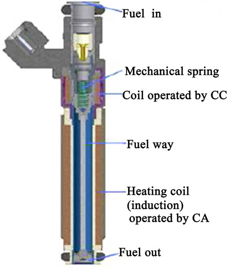
Figure 1. Heat tip injector and it is main components [2].
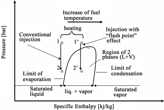
Figure 2. Diagram of pressure-specific enthalpy comparing between the conventional injection and the flash point injection [3].
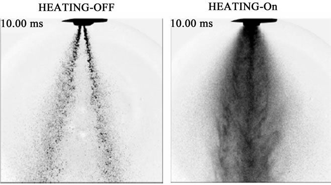
Figure 3. Comparison of the spray in the injection with and without heating [3]. P = 4.2 bar and T = 120˚C.
It has been estimated [4] that for ethanol at 120˚C and 4.2 bar injecting pressure a 17% of vapor quality (vapor mass fraction) can be achieved after injection. If the 120˚C temperature is exceeded, it may cause a blocking of the injector because of the accumulation of fuel vapor bubbles inside, a phenomenon known as vapor-lock or blocking.
3. Fuel Injector Thermal Modeling and Thermal Analysis
3.1. Lumped Analysis
In this section it is presented the thermal modeling of the heated tip fuel injector.
In order to carry out an analytical thermal modeling of the sensor, it is necessary to lay down a few simplifications, which are: 1) the injector needle mass is negligible and do not take part in the heating process; 2) natural convection occurs during the pre-heating process; 3) constant thermal transport properties; 4) lumped analysis is valid. Over all simplifications, the last one is the most relevant.
Figure 4 presents schematics of the injector for modeling purposes. The injector inner cylindrical wall is label 2 and label 1 is for ethanol inside the injector. The injector wall is heated up by the heat generated by the electromagnetic induction process. During the inner wall heating process, heat is transferred to the enclosed portion of ethanol by natural convection. Top and bottom edge effects are neglected and the actual core injector geometry is simplified to a simple cylindrical cavity filled up with ethanol at rest, whose validity spans up to prior to the ethanol injection.
It has been estimated [4] the average heat transfer coefficient, Ћ, at the inner wall by using the equation [5]. The average estimated value was Ћ = 300 W/m2·˚C. Also, in order to verify the validity of the lumped approach, Rezende [4] estimated a Biot number, Bi, in the order of 10 - 2, which falls within the range of validity.
For the application of the theory in this study, one must consider the heating of a certain amount of ethanol inside the injector from an initial and constant temperature T0. The time when the heating starts off is t = 0 s. Let us take the average heat transfer coefficient Ћ during the whole process to be constant. Also, let the lumped analysis be applied separately to the contained ethanol (label 1) and to the inner wall injector (label 2) as illustrated in Figure 4. On doing that, one will arise with two first order coupled ordinary differential equations that come from energy balances for both systems. The set of two equations requires a simultaneous solution.
So, for the ethanol:
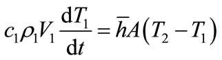 (1)
(1)
and for the injector inner wall:
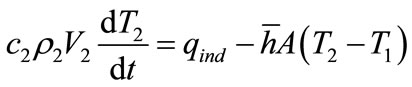 (2)
(2)
The initial conditions are T0 = T1 = T2 at t = 0 s.
The hypothesis that the ethanol and the inner wall of the injector can be considered isothermal is inherent to this uniform system approach.
Equations (1) and (2) make up a simultaneous linear differential system of equations that can be solved to obtain the time-evolution of the temperature of ethanol and of the inner wall of the injector.
Let Equations (1) and (2) be rewritten as:
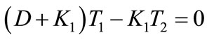 (3)
(3)
and
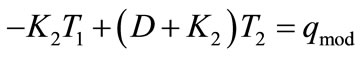 (4)
(4)
where the symbol “D” designates the time-derivative operator, i.e. D = d/dt,. Also, for convenience, it has been defined the following parameters:
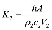
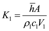 (5)
(5)
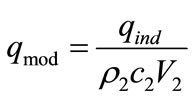
 (6)
(6)
and
 (7)
(7)
by working out the two differential Equations (3) and (4), it is possible to obtain a second order ordinary differential equation in T1, given by:
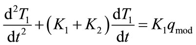 (8)
(8)
Whose solution is given by Equation (9):
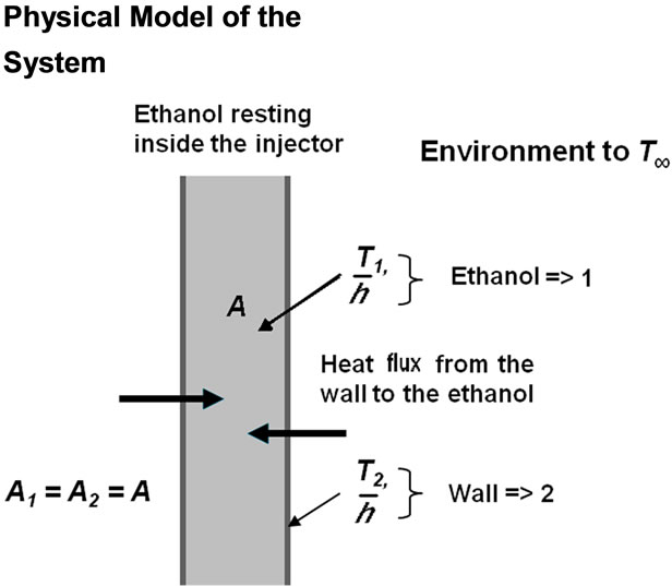
Figure 4. Simplified schematics of heated tip fuel injector. Ethanol (1) fills up the cylindrical fuel injector (2) heated by means of induction (electromagnetism).
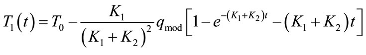 (9)
(9)
In similar way, one may isolate T2 to obtain:
and the solution for the injector inner wall is:
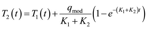 (11)
(11)
3.2. Sensitivity Analysis
The graph in Figure 5, shows the behaviour of the heating curves of both the ethanol and the injector inner wall as a function of time for a heating power qind = 100 W.
If one keeps all the other parameters unchanged, having the only varying the heating power of the injector, one can estimate the necessary time to reach a preset temperature. The needed pre-heating time is of extreme relevance because of driveability aspects of the vehicle. In the graph of Figure 6 one can see that the system preheating time to elevate the temperature of the ethanol between 5 and 80˚C, i.e., an increase of 75˚C takes 7.4 s for a heating power of 100 W; for qind = 150 W, the necessary time was 5.6 s; and, finally, qind = 200 W, the time was 4.8 s.
The heat transfer coefficient varies somewhat during the heating process due several factors involving transport properties dependency on temperature and natural convection regime. The graph in Figure 7 shows heating curves for three different heat transfer coefficients, namely, Ћ: 100, 400 and 800 W/m2·˚C.
4. Results and Discussions
Experimental data on the heating curve of ethanol bulk temperature as a function of time were obtained by introducing a tiny thermocouple inside the injector [2]. In Figure 8 those experimental data were compared with the heating curve according to this model for a temperature rise from 0 to 80˚C, with an average coefficient of heat transfer of 400 W/m2·˚C, and input power of 100 W. The overall heating process took about 9 s. As seen in that figure, in the beginning of the heating process, actual ethanol temperature rises faster than the one anticipated by the model and, then, it rises less and less to attach more closely to the model. A possible explanation to this problem is associated with the very nature of the lumped model, which supposes constant transport properties as well as the heat transfer coefficient. Concerning the average heat transfer coefficient it should be obtained through empirical tests for each situation.
Besides the assumption of invariable transport properties there are other sources of divergence with the lumped model that should also be considered. Firstly, the injector
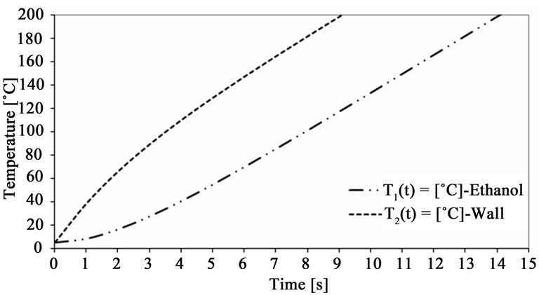
Figure 5. Time-history of temperature rise of ethanol and the inner injector wall in function of the time to a heating power of 100 W e Ћ= 300 W/m2·˚C.
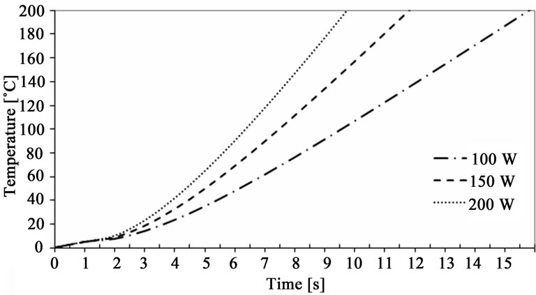
Figure 6. Comparative graph of heating power applied to the injector.
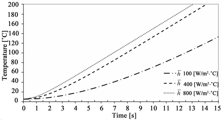
Figure 7. Comparative graph of results with the variation of the average coefficient of heat transfer.
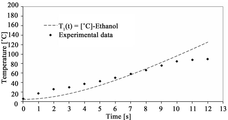
Figure 8. Comparison between lumped solution and experimental data.
needle was not considered in the calculation of the modeling, which has a non-negligible mass from the thermal point-of-view. Secondly, edge effects were neglected and some conductive heat transfer is expected from the injector inner wall to the injector body itself. Finally, as electrical energy is supplied to the system, there are some losses along the electrical system. The determination of those losses was not considered, which is another factor responsible for the difference between the results.
5. Conclusions and Suggested Future Work
This work aimed at to develop a mathematical model able to estimate the elevation of the temperature inside the injector as a function of time, considering the variables involved in the heating process. In order to do so, some simplifying hypotheses were identified based on the hypothesis of lumped systems approach. As part of it the injector inner wall and the portion of ethanol inside of the injector were considered as two lumped systems, which resulted in two controlling and coupled differential equations (Equations (1) and (2)). The coupling between them was taken in through the heat transfer from the wall to the ethanol. Next, those differential equations were solved, which allowed the heating curves to be obtained as a function of time and the other parameters involved. An analysis of sensitivity in different conditions was performed to verify the impact of various parameters over the simulation results. Some variations of heating power and the average coefficient of heat transfer were simulated, obtaining the heating curves as function of time.
Tests with injectors assembled in an engine were performed [4] inside a cold chamber in order to compare the results obtained with those resulting from the mathematical simulations. It was verified that the modeling showed good agreement, even though considering the several restrictions approach.
The estimation of the average coefficient of heat transfer Ћ demands the performance of empirical tests, since its exact determination cannot be found in open literature for the specific case of study. Due to this fact, a “calibration” factor was proposed of the model from Ћ, in order to adjust the modeling with the purpose of use of simulation, showing satisfactory result levels.
The proposed model can also be implemented in the algorithm of the engine electronic management system software in order to estimate the temperature of the fuel inside the injector and the time for it to reach its target value, because the vehicle start procedure will only be allowed by the PCM after the time has elapsed and the target temperature is reached. Because the injectors to be serially manufactured do not have thermocouples to indicate the system about its temperature, the modeling is a tool to solve this issue.
Finally, the proposed mathematical modeling reached its initial goal, which was to elaborate a model that could be simulated, using the various parameters involved in the process, and that could guide the development of this new component, saving some money with the building of samples, reducing the time of the tests and the whole cost, which is a relevant factor in the development and feasibility of new products in the modern automotive industry.
As a suggestion for future work, the modeling could be improved in a numerical software platform for a condition of dynamic flow of the injector aiming at to estimate the temperature of the ethanol in the injector during the pre-heating phase, and also after the engine start in different conditions of idle, cold-drivability and measurements of vehicular emissions in order to check the impact of the heating of the fuel on the emissions results.
REFERENCES
- M. S. Rocha and J. R. Simões-Moreira, “A Simple Impedance Method for Determining Ethanol and Regular Gasoline Mixtures Mass Contents,” Fuel, Vol. 84, No. 4, 2005, pp. 447-452. doi:10.1016/j.fuel.2004.09.011
- Z. Fono, “An Empirical Study of the Heat Transfer of Three Inductively Heated Injector Concepts Using Alcohol Fuel E100,” Siemens VDO Automotive AG, 2007.
- P. Hofmann and P. H. Lenz, “Ein schnell ansprechendes Flash-Boiling-Einspritzventil zur Verminderung der Emissionen im Kaltstart und Warmlauf,” Vortrag am 21, Internationales Wiener Motorensymposium, 2000.
- A. Rezende, “Thermal Modeling of Heated Tip Injectors for Otto Cycle Engines,” Master Dissertation, Escola Politécnica da Universidade de São Paulo, São Paulo, 2009.
- S. W. Churchill and H. H. S. Chu, “Correlating Equations for Laminar and Turbulent Free Convection from a Vertical Plate,” International Journal of Heat and Mass Transfer, Vol. 18, No. 11, 1975, pp. 1323-1329. doi:10.1016/0017-9310(75)90243-4
Appendix
NOTES
*This work was supported by Continental Indústria Automotiva Ltda.
#Corresponding author.