Communications and Network
Vol.3 No.1(2011), Article ID:3994,8 pages DOI:10.4236/cn.2011.31005
Pilot Placement for Time-Varying MIMO OFDM Channels with Virtual Subcarriers
Electrical Engineering Department, Shahed University, Tehran, Iran
E-mail: moradi@shahed.ac.ir
Received October 13, 2010; revised January 7, 2011; accepted January 19, 2011
Keywords: guard band, MIMO OFDM, pilot, time-varying channel, virtual subcarriers
Abstract
The rapid time-variation of a fading multipath environment can impair the performance of multiple-input multiple-output orthogonal frequency division multiplexing (MIMO OFDM). This paper proposes a pilot placement method for MIMO OFDM systems under time-varying channels with the guard band. The time-varying channel is described by complex exponential basis expansion model (BEM). We discuss the least square (LS) channel estimation to obtain the minimum mean square error (MSE) and derive the pilot allocation that can satisfy the minimum MSE with regard to guard band in time-varying channels. It is shown that optimal pilot clusters can distribute non-uniformly in frequency domain and minimize the MSE. We generalize our scheme over G OFDM symbols and compare it with comb pilots. It is demonstrated that the proposed approach is more effective than previous work. Simulation results validate our theoretical analysis.
1. Introduction
Orthogonal frequency division multiplexing (OFDM) gives an effective technique for high data rate transmission. A multiple-input multiple-output (MIMO) system increases system capacity and provides diversity in fading environment [1]. The combination of MIMO and OFDM offers high system throughput.
A pilot signal design is presented in [2] for MIMO OFDM system. The least square (LS) channel estimation is used for channel coefficients. To obtain the minimum MSE, an equal-powered, equal-spaced and phase shift orthogonal pilot sequence is suggested. In [3], the training sequences are designed for OFDM system where pilot tones satisfy the optimal conditions. The placement of pilot symbols is studied in [4] for single-carrier and OFDM systems. The problem of setting and design of pilot sequences is considered in [5] for the frequencyselective channel estimation. The Cramer-Rao Bound (CRB) in order to the minimum MSE of the channel estimation is computed for both single-input single-output and MIMO systems. The optimal pilot allocation is described in [6] for OFDM system. As supposed in it, the channel must be quasi static and have a finite impulse response. The energy exchange between the pilot and data is also derived optimally. In order to derive an optimum estimation, [7] also discussed the selection of pilot tones. As shown in it, the training sequences with equal space have the best performance. In [8], the training sequences with virtual subcarriers are presented. The pilot placement is non-uniform and gives the minimum MSE of the LS channel estimation. In practice systems, the presence of the virtual subcarriers can cause nonuniform pilot placement. To achieve optimal conditions, it applies the algorithm which is given in [9] for solving the linear inequalities. In [10], a pilot design scheme for the LS channel estimation is described in MIMO OFDM systems. A suboptimal pilot sequences is also suggested for reduction of the training overhead. General groups of pilot sequences are addressed in [11] for frequency-selective channel estimation in MIMO OFDM systems. Various pilot sequence allocations are arranged for each transmit antenna. These allocations are organized as follows: time-division multiplexing, frequency-division multiplexing, code-division multiplexing in the frequency domain and in the time domain, and different combinations of them.
For multiple antennas, a pilot design approach is proposed in [12], where the data sequences transmit over frequency-selective channels. This low complexity scheme is based on the maximum a lower bound of the average capacity. In [13], the estimation of the correlation matrices for fading channels is considered. The pilot signals are used for obtaining the channel coefficients. The channel variations are modeled as multichannel autoregressive (AR). The peaks of the AR spectrum show the Doppler frequencies.
A pilot approach is considered in [14] for MIMO OFDM systems in time-varying channels. To increase the performance, the inter-carrier interference (ICI) due to time variations must be decreased in high delay environments. In [15], the channel estimation for MIMO OFDM systems is expressed in linearly time-varying channel. The channel coefficients of the linearly timevarying channel are based on complex exponential basis expansions model. In direct sequence code division multiple access (DS-CDMA) systems, [16] expresses an adaptive estimation of Doppler shifts for several Doppler sub-paths. The channel model is based on basis expansion model (BEM). For suppression of ICI in timevarying channel, [17] presents an analytical framework dependent on the known statistical properties with mobile radio channels. [18] uses a parallel removal technique for discarding ICI in frequency domain. It is supposed that the channel impulse response (CIR) changes linearly along a block period. For time-varying frequencyselective channels, a general framework is described in [19] to achieve the optimal pilot overhead and the optimal pilot boost. For single-input multiple-output timevarying channels, blind channel estimation is given in [20], where the time-varying channel is expressed as a complex exponential basis expansion model (CEBEM). For frequency-selective fading channel estimation, a rectangular-windowed least square estimation is studied in [21], relying on a polynomial model of the timevarying channel delays. For channel estimation, a new block differential codec is derived in [22]. The timevarying channels are described as a basis expansion model. By using the BEM, block differential design has a simple implementation, and derives the maximum Doppler diversity in the time-varying channels.
So as to discard the interference between neighboring channels in practical systems, a guard band is considered at each transmit data symbol. The guard band includes virtual subcarriers that are not used for transmission. In [23], a pilot placement is suggested regard to the guard band. It implies that comb pilots with the largest distance between pilot tones have the best effectiveness by exploiting the equivalence of the Toeplitz and circulant matrices. In this paper, we suggest an optimal pilot allocation that does not rest in the guard band based on the minimum MSE under time-varying channel. We also show that our new scheme has better performance than comb pilots.
The remainder of the paper is organized as follows: Section 2 expresses the basis expansion model for timevarying channels and describes the MSE of the LS channel estimation. To obtain the minimum MSE, the optimal conditions are also derived in this section. In Section 3, we introduce a new pilot allocation that is optimal with respect to virtual subcarriers. We organize our method over G OFDM symbols in Section 4. Section 5 contrasts our scheme with comb pilots. Section 6 presents the simulation environment and outcomes, and shows improvement in our design. Eventually, the conclusions are expressed in Section 7.
Notations:  is used to show the matrix trace.
 ,
,  and
and  express conjugate, transpose and conjugate transpose respectively.
  is applied for the cyclic convolution. Expectation is presented by
 . The ceiling of a number is shown by
 .
.  denotes the set of integer numbers. Bold letters is presented for matrices (column vectors) and variables are displayed in italic.
2. System Model
The desired system is depicted in Figure 1. It is a MIMO OFDM system with  transmit antennas,
  receive antennas and K subcarriers. The length of channel impulse response (CIR) is equal to L for each transmit-receive antenna pair. A cyclic prefix (CP) with length V is inserted to form a complete OFDM symbol. The CP is considered to be larger than the largest multipath delay. The channel estimation procedure is applied similarly at each receive antenna, so we assume to have
  transmit antenna and one receive antenna.
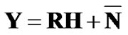
Let  be the data symbol on nth time sample at ith transmit antenna. After removal the CP at the receiver, the output can be written as
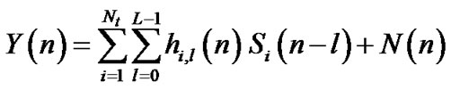 (1)
(1)
where 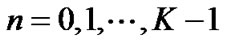 and
and  is additive Gaussian noise with zero mean and variance of
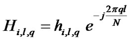
 . The channel coefficient can be approximated by a complex exponential model as
 (2)
(2)
where  is zero mean, complex Gaussian random variables with equal variance
 . Since the BEM is periodic with period of N and the real channel is not periodic, N must be larger than the length of transmit data, i.e.,
 .
.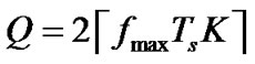 ,
,  is the maximum Doppler frequency,
  is the sample interval and
  is the total interval of data symbol [14].
Define:
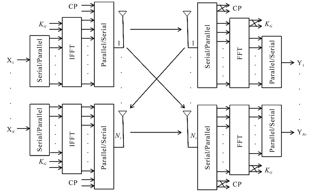
Figure 1. System model.
 (3)
(3)
 (4)
(4)
 (5)
(5)
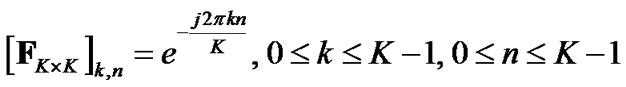
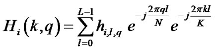
then, with above definition, the fast Fourier transform (FFT) of Y(n) is given by
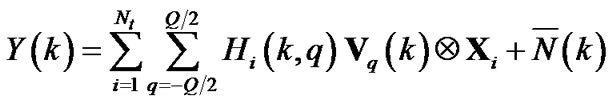 (6)
(6)
where  and
and  is the FFT of
  with variance of
 .
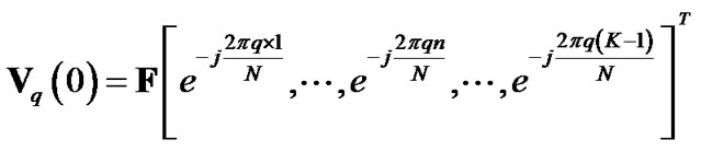
.  is the transmit data vector in frequency domain, i.e.,
 .
.  denotes a cyclic shift vector of
  with a shifting length k.
As discussed in [15], the major power of the vector  concentrates on two ends. So,
  can be approximated by
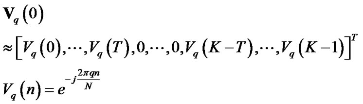 (7)
(7)
where T is a positive number. T = 2 or 3 is sufficient for involving the principal lobe of . Since the convolution between
  and
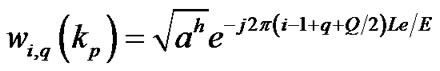
and  is only performed at 2T + 1 sequential tones around the tone k, we use pilot clusters with length 2T + 1. We consider pilot clusters on a set of subcarriers
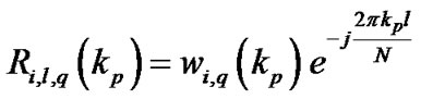
 . P denotes the number of pilot clusters. So the pilot sequences at the pilot cluster
  is
is
 at ith transmit antenna.
Define:
 (8)
(8)
 (9)
(9)
 (10)
(10)
Then at all pilot clusters, the equation (6) can be written as
 (11)
(11)
where R is a  matrix. The least square channel estimation, supposing
 has full rank and
 , is given by [24]
 (12)
(12)
From (12), the MSE of the LS channel estimation can be obtained as
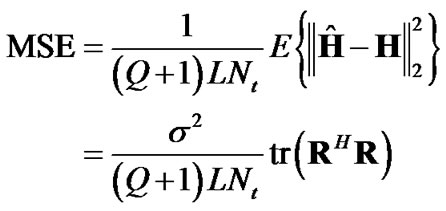 (13)
(13)
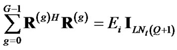
In order to obtain the minimum MSE of the LS channel estimation with fixed energy  allocated for pilot sequences, we must have
 (14)
(14)
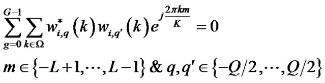
where I shows an identical matrix. For achieving (14) and minimizing the MSE in (13), we must satisfy the following condition as
 (15)
(15)
where . For
. For , we have
 (16)
(16)
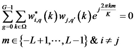
finally, for two different transmit antennas and , we require
 (17)
(17)
3. Pilot Placement with Guard Band
In practical system, some of subcarriers are not use for transmission that called virtual subcarriers. The virtual subcarriers set in the guard band. For avoiding the interference between communication channels, the guard band is considered at each transmit data sequence. The transmit subcarriers are assumed to be belonged to
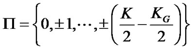
where  denotes the number of the virtual subcarriers. The purpose is to estimate the channel impulse response under time-varying channel with guard band. Therefore, we suggest the pilot placement that minimizes the MSE in the presence of the guard band under the BEM.
As discussed in previous section, for minimizing the MSE, the conditions (15), (16) and (17) must equal to zero. In this paper, for simplification, it is assumed K is even and  is odd. Let
 . Define M as the number of pilot cluster groups at each transmit symbol, where E is the number of pilot clusters and
  is the distance between pilot clusters at each groups. So, we have M pilot cluster groups at each transmit antenna. Since pilot tones are outside the guard band, the distance between pilot clusters at each group must be larger than the length of the guard band, i.e.,
 . The condition of full rank
  shows that we should have at least
  pilot clusters, i.e.
 . Consider
  is the power allocated for each pilot in hth group, where
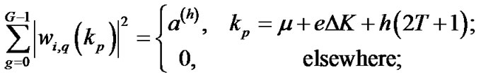
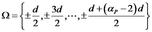
 . The following pilot allocation is proposed as
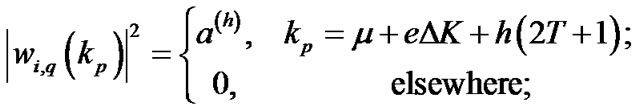 (18)
(18)
where ,
,  and
and . The problem is to find M and imply that the pilot allocation (18) satisfies (15), (16) and (17) with regard to the guard band.
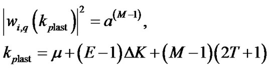
1) for e = 0 and h = 0, the relation (18) can be expressed as
 (19)
(19)
as seen,  is the middle tone at each pilot cluster. So, the first tone places at
  and the last ton sets at
 .
.  is the first edge of the subcarriers that is outside the guard band.
2) for e = E − 1 and h = M − 1, we have
 (20)
(20)
where 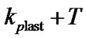 is the last tone of the last cluster that should be outside the guard band. It means
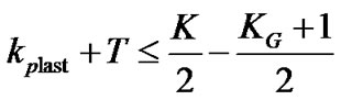 (21)
(21)
 (22)
(22)
then, M can be written as
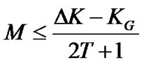 (23)
(23)
for above M, our proposed pilot placement do not include the virtual subcarriers. Figure 2 illustrates subcarriers with guard band.
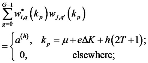
Now, we should demonstrate this pilot allocation zeros (15), (16) and (17).
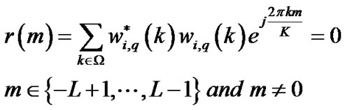
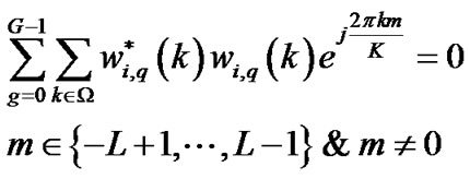
3) with substituting condition (18) in (15), it can be given by
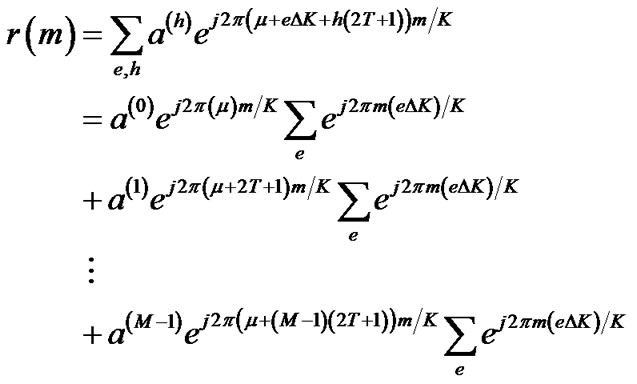 (24)
(24)
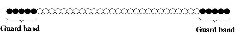
Figure 2. Subcarriers with guard band.
it is implied
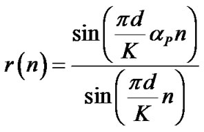
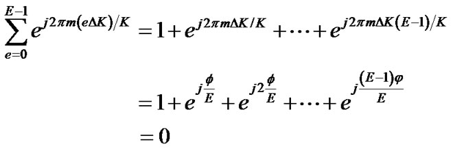 (25)
(25)
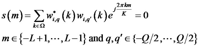
where . We corroborate that r(m) is zero for our pilot allocation. For minimizing the MSE, s(m) and d(m) should also become zero.
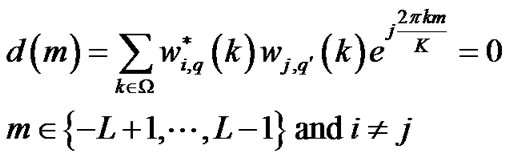
4) for two different transmit antennas and , the training sequence is designed as
 (26)
(26)
After, setting (26) in (17), it can be obtained
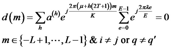 (27)
(27)
where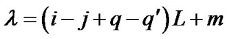 . Since
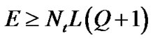 ,
,
 is always smaller than E and
  becomes zero for all m. Therefore, we introduce a new pilot placement under time-varying channel with regard to the guard band that minimizes the MSE and achieves the optimal conditions. We can generalize our scheme over G OFDM symbols.
Table 1 shows an example of our pilot allocation in four groups. Consider two transmit antennas. Let K = 516, L = 3,  , Q = 1 and T = 2. As known
 , so we choose E = 12 and
 . Relation (23) provides M = 4. Each group has 12 pilot clusters and each cluster requires 5 pilot tones.
4. Pilot Placement over G OFDM Symbols
In this section, we suppose G OFDM symbols at each transmit antenna. Let  be
be  at gth OFDM symbol. With this consideration, condition (14) changes to
 (28)
(28)
where  is R at gth OFDM symbol.
From (28), conditions (15), (16) and (17) can be written as
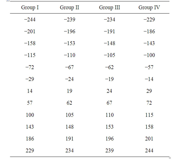
Table 1. Placement of pilot clusters for ,
,  ,
,  ,
,  and
and .
.
 (29)
(29)
For , it is given by
 (30)
(30)
For two different transmit antennas and , it can be obtained as
 (31)
(31)
To achieve (29), we can write (18) as
 (32)
(32)
where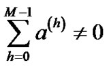 .
.
From (30) and (31), we can express
 (33)
(33)
5. Comparing the Proposed Method with Comb Pilot
We described pilot sequences that can minimize the MSE for time-varying channel with virtual subcarriers. Now, we interest to contrast our method with comb pilots which have equal space and equal power without crossing the guard band. In [23], comb pilots are used for single input single output OFDM systems in the presence of the guard band. Without considering the virtual subcarriers, pilots with equal space and equal power can optimize (13) with uniform eigenvalues. As known, comb pilots do not place in the guard band and can not optimize the MSE of the LS channel estimation. So, [23] presents a semi-optimal scheme. The equivalence of r(m), with assumption of [23], is given by
 (34)
(34)
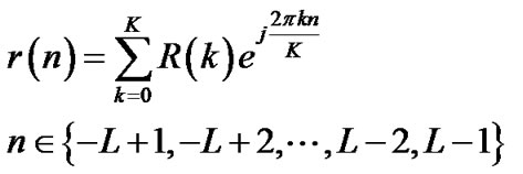
for , R(k) is equal to 1, i.e.,
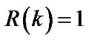 . Let
. Let  be the number of pilot clusters which distribute symmetric about the origin. Then, we have
 . The inverse discrete Fourier transform of R(k) is written as
 (35)
(35)
the energy of r(n) diminishes rapidly with raising n for comb pilots. It is shown in [23] that comb pilots with larger distance between pilot tones have better signal to noise ratio because the largest space has the narrowest main lobe.
If we choose , r(m) of condition (15) will be equal to one for m=0, i.e.,
  and will become zero for
 . Thus, r(m) illustrates an impulse function. With this consideration, r(m) is equivalence to r(n) given in [23]. Our proposed method achieves conditions (15), (16) and (17). In comparison with comb pilots, r(m) has the narrowest main lobe and becomes zero suddenly in
 . Therefore, our proposed pilot setting is optimum while comb pilots are sub-optimal.
6. Simulation and Results
We consider two transmit and two receive antennas for MIMO OFDM system. The modulation mode is chosen as BPSK. The channel is supposed to have L = 3 and V = 5. The OFDM symbol size is selected as K=516 and the length of the guard band is . We assume that the channel coefficients are distributed identically and independently by complex Gaussian random process. The symbol rate is
  or
or  and the maximum Doppler frequency is
 . N = 5120 is chosen, where N > K. We select Q = 1 and T = 2, so the length of the pilot cluster is 2T + 1 = 5. As known, E must be equal or larger than
 . Consider E = 12 and
  because of
 . The relation (23) shows that M can be at most 4. We only suppose two groups in our simulation in Figure 3 and Figure 4, i.e., M = 2. The number of total pilot clusters is ME = 24 and the total pilot tones are equal to (2T + 1) ME = 120.
The multi-path density profile is considered as 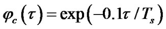 and the Doppler power spectrum is
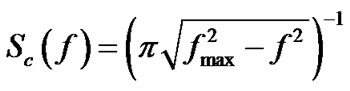 , where
 .
.
Figure 3 shows the bit error rate (BER) versus signal to noise ratio (SNR) for the time-varying BEM. The distance between comb pilot cluster 1 is d = 20 and the pilot clusters are belonged to the set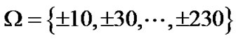 . The set of comb pilot cluster 2 is
 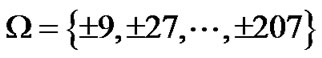 , where the distance between them is chosen as d = 18. The amplitude of pilot tones is equal to each other. The pilot clusters of proposed approach are placed at
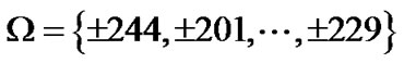 , where these tones are selected from group I and group IV in Table I. The amplitude of pilot tones is followed by relation (26). Since we only have two groups, so
  and
and  are zero. As seen, the comb pilot cluster 1 has better effectiveness than comb pilot cluster 2 because of the larger distance between them. The proposed approach yields performance improvements greatly compared to comb pilot clusters.
Figure 4 illustrates the MSE versus SNR for comb pilot cluster 1, comb pilot cluster 2 and proposed approach. By comparison between curves, it is concluded that the proposed scheme is the best.
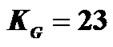
Figure 5 compares the MSE of proposed approach for different Doppler frequencies as , 200 Hz and 500 Hz. We consider four groups and the total pilot tones are 240, therefore
  and
and  are non-zero. The simulation results show that the effectiveness of the MSE is decreased with increasing Doppler frequency.
7. Conclusion
In this paper, the problem of the pilot placement was studied for time-varying channel estimation with virtual subcarriers. First, we described the BEM for the LS channel estimation under time-varying channels and then, we expressed the optimal conditions based on the mini-
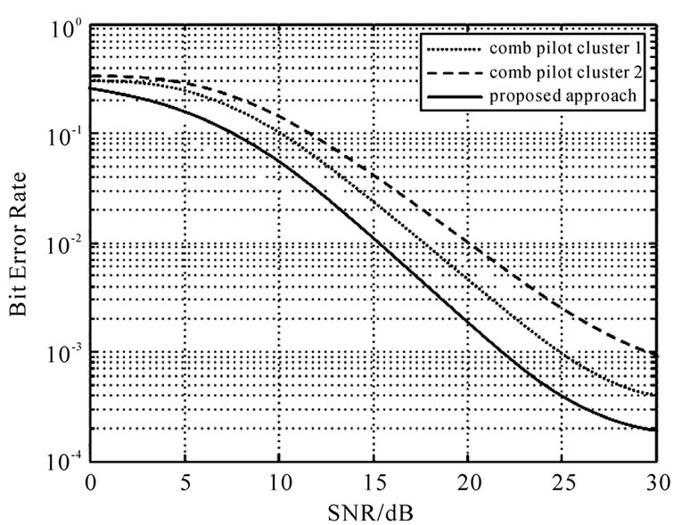
Figure 3. BER performance for pilot placement,  ,
,  ,
,  and
and .
.
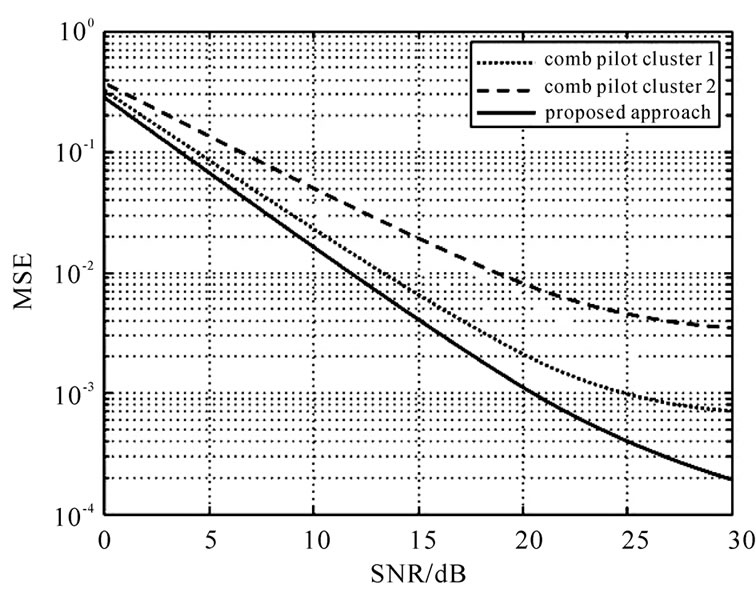
Figure 4. MSE performance for pilot placement,  ,
,  ,
,  and
and .
.
Figure 5. MSE performance for different Doppler frequency,  ,
,  ,
,  and
and .
.
mum MSE. We suggested a new pilot allocation that is distributed non-uniformly with non-equally powered pilot tones. We arranged the proposed pilot cluster over G OFDM symbols and gave an example of the pilot setting in four pilot groups. After contrasting our design with comb pilots, it was shown that the proposed scheme improves SNR. Simulation results also verify our idea.
8. References
[1] M. Jankiraman, “Space-Time Codes and MIMO Systems,” Artech House, London, 2004.
[2] I. Barhumi, G. Leus and M. Moonen, “Optimal Training Design for MIMO OFDM Systems in Mobile Wireless Channels,” IEEE Transactions on Signal Processing, vol. 51, no. 6, June 2003, pp. 1615-1624. doi:10.1109/TSP. 2003.811243
[3] J. Manton, “Optimal Training Sequences and Pilot Tones for OFDM Systems,” IEEE Communications Letters, vol. 5, no. 4, April 2001, pp. 151-153. doi:10.1109/4234.9170 97
[4] S. Adireddy, L. Tong and H. Viswanathan, “Optimal Placement of Training for Frequency-Selective BlockFading Channels,” IEEE Transactions on Information Theory, vol. 48, no. 8, August 2002, pp. 2338-2353. doi:10.1109/TIT.2002.800466
[5] M. Dong, and L. Tong, “Optimal Design and Placement of Pilot Symbols for Channel Estimation,” IEEE Transactions on Signal Processing, vol. 50, no. 12, 2002, pp. 3055-3069. doi:10.1109/TSP.2002.805504
[6] S. Adireddy, L. Tong and H. Viswanathan, “Optimal Embedding of Known Symbols for OFDM,” Proceedings of ICASSP’01, vol. 4, 2001, pp. 2393-2396.
[7] R. Negi and J. Cioffi, “Pilot Tone Selection for Channel Estimation in a Mobile OFDM System,” IEEE Transactions on Consumer Electronics, vol. 44, no. 3, August 1998, pp. 1122-1128. doi:10.1109/30.713244
[8] Hu, L. Yang, Y. Shi and L. He, “Optimal Pilot Sequence Design for Channel Estimation in MIMO OFDM Systems,” IEEE Communications Letters, vol. 10, no. 1, January 2006, pp. 1-3. doi:10.1109/LCOMM.2006.1576 550
[9] D. L. Xinming and W. Fang, “A New Algorithm for Solving Systems of Linear Inequalities,” ACTA Mathematicae Applicatae sinica, vol. 18, July 1995, pp. 340- 343.
[10] Z. Lu, and J. H. Ge, “Time-Domain Training Sequences Design for MIMO OFDM Channel Estimation,” Journal of Zhejiang University SCIENCE A, vol. 9, no. 4, December 2007, pp .464-469.
[11] H. Minn and N. Al-Dhahir, “Optimal Training Signals for MIMO OFDM Channel Estimation,” IEEE Transactions on Wireless Communications, vol. 5, no. 5, May 2006, pp. 1158-1168.
[12] X. Ma, L. Yang, and G. Giannakis, “Optimal Training for MIMO Frequency-Selective Fading Channels,” IEEE Transactions on Wireless Communications, vol. 4, no. 2, March 2005, pp. 453-466. doi:10.1109/TWC.2004.8429 98
[13] M. K. Tsatsanis and Z. Xu, “Pilot Symbol Assisted Modulated in Frequency Selective Fading Wireless Channels,” IEEE Transactions on Signal Processing, vol. 48, no. 8, August 2000, pp. 2353-2365. doi:10.1109/78. 852 016
[14] X. Wu and G. Kang, “Pilot Sequence Design Scheme for MIMO OFDM Systems under Time-Varying Channels,” IEEE Wireless Communication Conference, Singapore, May 2008, pp. 777-781.
[15] X. Dai, “Optimal Training Design for Linearly TimeVarying MIMO/OFDM Channels Modeled by a Complex Exponential Basis Expansion,” IET Communications, vol. 1, no. 5, 2007, pp. 945-953. doi:10.1049/iet-com:200453 01
[16] T. Wang, C. Li and H. Chen, “Basis Expansion Model and Doppler Diversity Techniques for Frequency Domain Channel Estimation and Equalization in DS-CDMA Systems,” Proceedings of ICC’07, 2007, pp. 4907-4912.
[17] A. Gorokhov and J. P. Linnartz, “Robust OFDM Receivers for Dispersive Time-Varying Channels: Equalization and Channel Acquisition,” IEEE Transactions on Communications, vol. 52, no. 4, 2004, pp. 572-583. doi:10. 1109/TCOMM.2004.826354
[18] W. Hou and B. Chen, “ICI Cancellation for OFDM Communication Systems in Time-Varying Multipath Fading Channels,” IEEE Transactions on Wireless Communications, vol. 4, no. 5, 2005, pp. 2100-2110. doi:10.1109/ TWC.2005.853837
[19] I. Cosovic and G. Auer, “Capacity Achieving Pilot Design for MIMO-OFDM over Time-Varying FrequencySelective Channels,” Proceedings of ICC’07, 2007, pp. 779-784.
[20] J. K. Tugnait and W. Luo, “Linear Prediction Error Method for Blind Dentification of Periodically TimeVarying Channels,” IEEE Transactions on Signal Processing, vol. 50, no. 12, 2002, pp. 3070-3082. doi:10. 1109/TSP.2002.805493
[21] D. K. Borah and B. D. Hart, “Frequency-Selective Fading Channel Estimation with a Polynomial Time-Varying Channel Model,” IEEE Transactions on Communications, vol. 47, no. 6, 1999, pp. 862-873. doi:10.1109/26.771 34 3
[22] X. Ma, G. B. Giannakis and B. Lu, “Block Differential Encoding for Rapidly Fading Channels,” IEEE Transactions on Communications, vol. 52, no. 3, 2004, pp. 416- 425. doi:10.1109/TCOMM.2004.823604
[23] S. Song and A. Singer, “Pilot-Aided OFDM Channel Estimation in the Presence of the Guard Band,” IEEE Transactions on Communications, vol. 55, no. 8, August 2007, pp. 1459-1465. doi:10.1109/TCOMM.2007.902526
[24] S. M. Kay, “Fundamentals of Statistical Signal Processing: Estimation Theory,” Prentice Hall PTR, Upper Saddle River, 1993.