World Journal of Mechanics
Vol. 3 No. 2 (2013) , Article ID: 30873 , 7 pages DOI:10.4236/wjm.2013.32011
Occurrence of Dynamic Shear Bands in AISI 4340 Steel under Impact Loads
1Department of Mechanical Engineering, Howard University, Washington DC, USA
2Department of Mechanical Engineering, University of Saskatchewan, Saskatoon, Canada
Email: *gbadebo.owolabi@howard.edu
Copyright © 2013 Gbadebo Owolabi et al. This is an open access article distributed under the Creative Commons Attribution License, which permits unrestricted use, distribution, and reproduction in any medium, provided the original work is properly cited.
Received January 31, 2013; revised March 9, 2013; accepted March 16, 2013
Keywords: Adiabatic Shear Band; Finite Element Model; Strain Hardening; Thermal Softening; Johnson-Cook Model; AISI 4340 Steel
ABSTRACT
In this study, occurrence of adiabatic shear bands in AISI 4340 steel under high velocity impact loads is investigated using finite element analysis and experimental tests. The cylindrical steel specimen subjected to impact load was divided into different sections separated by nodes using finite element method in ABAQUS environment with boundary conditions specified. The material properties were assumed to be lower at the section where the adiabatic shear bands are expected to initialize. The finite element model was used to determine the maximum flow stress, the strain hardening, the thermal softening, and the critical strain for the formation of adiabatic shear bands. Experimental results show that deformed bands were formed at low strain rates and there was a minimum strain rate required for formation of transformed band in the alloy. The experimental results also show that cracks were initiated and propagated along transformed bands leading to fragmentation under the impact loading. The susceptibility of the adiabatic shear bands to cracking was markedly influenced by strain-rates. The simulation results obtained were compared with experimental results obtained for the AISI 4340 steel under high strain-rate loading in compression using split impact Hopkinson bars. A good agreement between the experimental and simulation results was obtained.
1. Introduction
During impact loading, heat is generated as a result of the conversion of kinetic energy of the projectile to heat energy during deformation. The heat generated leads to thermal softening which occurs simultaneously with strain hardening as the deformation process continues. The strain eventually becomes localized along narrow bands due to intense localized adiabatic heating and the associated thermal softening and loss of load carrying capability along these narrow bands. These narrow bands of intensely localized strains are referred to as adiabatic shear bands (ASBs). As a result of severe plastic deformation occurring along ASBs, these bands consist of intensely distorted grains or fragmented grains in metallic materials exposed to high strain-rate deformation [1]. The occurrence of adiabatic shear bands has been reported in metallic materials subjected to high strain loading in compression and in torsion. Adiabatic shear banding has been reported to precede fragmentation and failure of components subjected dynamic shock loading [2-5]. Strain localization leading to formation of adiabatic shear bands is not only peculiar to metallic materials. This phenomenon has also been observed in ceramic materials [6,7] and polymeric materials [7,8] after exposure to dynamic shock loading.
During high strain-rate deformation, tensile stresses are generated inside shear bands as a result of the lower flow stress inside the adiabatic shear bands compared to the outside. Figure 1 illustrates the microstructural evolution leading to formation of cracks within an adiabatic shear band. The tensile stresses generated inside the shear bands eventually become sufficiently high enough to open up micro-pores which coalesce to form voids that elongate and rotate to form elliptical shapes with major axis along the shear bands propagation path. These elliptical voids are finally connected, initiating cracks which propagate along the shear band leading ultimately to fracture. An adequate understanding of ASB formation in materials is very critical to mechanical design for components used in many practical applications involving
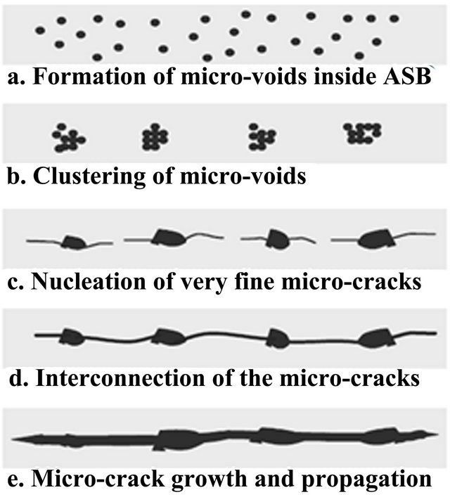
Figure 1. Microstructural model for crack initiation and propagation inside adiabatic shear band in martensitic AISI 4340 steel [9].
rapid and severe deformation such as explosive loading [10-12], high speed machining [5,13], metal forging, and ballistic or high velocity impact [14].
The adiabatic shear bands consisting of severely distorted grains are called deformed bands while those consisting of nano-size subgrains are called transformed or white etching bands. Although deformed bands are commonly associated with non-ferrous alloys while transformed bands are suggested to predominantly form in ferrous alloys, the type of bands that will develop in an alloy at high strain rates depend on the composition, heat treatment condition and severity of loading. For example an oil quenched high strength low alloy steel tempered at 600˚C formed deformed bands under high velocity impact while the same steel formed transformed bands under similar loading condition when tempered at 300 or 400˚C [1]. Transformed bands are also called white etching bands because of their white colour under an optical microscope after etching with nitial. As a result of their extremely fine microstructure, transformed bands are known to be harder and more brittle than the bulk material [1]. The microstructure inside transformed bands cannot be resolved under optical or scanning electron microscope. However, observations of transformed adiabatic shear bands using transmission electron microscope in many materials indicate that they consist of very fine grains of submicron size [14].
The formation of ASBs has been explained using theories such as phase transformation dynamic recrystallization, dynamic recovery, and progressive sub-grain misorientation [15-19]. During adiabatic heating, the rise in temperature which occurs in the ASBs is suggested to be high enough to cause transformation to austenite along the adiabatically heated path. Rapid quenching by the surrounding matrix is reported to cause the transformation of the austenite to untempered marten site. However, based on the relatively short space of time within which the high strain rate deformation occurs, it is doubtful if the phase transformation to untempered martensite is possible in transformed bands [16]. The formation of ultrafine-grained transformed bands in steel has also been explained using dynamic recovery mechanism [17]. The final stage of the recovery process involves spheriodization of the fragmented grains resulting in formation a shear band having densely packed fine subgrains. Considering the deformation time during which the transformed bands are formed, static recrystallization is inadequate to explain the formation of fine equi-axed grains in transformed bands [18]. Dynamic recrystallization mechanism has been used to explain the formation of transformed bands in metallic alloys. Dynamic recrystallization has been observed to occur in four stages [19]: 1) multiplication of dislocations which are dispersed randomly; 2) arrangement of dislocations in the form of elongated dislocation cells; 3) generation of sub-grains by dislocating patterning as deformation progresses; and 4) break down of sub-grains into equi-axed submicron size grains and grain rotation.
The prevalent models for explaining the occurrence of ASBs in metallic alloys include the Zerilli and Armstrong model [20], the Johnson Cook model [21], and Clifton model [22]. The Zerilli and Armstrong model is a dislocation pile up model where the blocking of dislocation on a slip plane by obstacles leads to extensive strain causing the formation of bands. This model uses dislocation mechanics concept to develop flow stress method in accounting for strain rate, strain, and temperature during dynamic impact loading. The Johnson Cook model is a well-accepted and numerically robust model which is based on a strain at fracture criteria. The slope of the flow stress curve is independently affected by strain hardening, strain rate sensitivity and thermal softening behaviors in the Johnson Cook model.
In this paper, finite element modeling of the formation of ASBs in AISI 4340 steel is performed using the Johnson Cook model. The effect of microstructural defect and striker bar velocity on the formation of adiabatic shear bands in AISI 4340 is also determined. The characteristics of adiabatic shear bands observed in the impacted steel alloy were investigated in relation to the pre-impact microstructure of the steel specimens.
2. Material System and Experimental Method
The material investigated in this study is AISI 4340 alloy steel containing 0.40% C and varying degrees of alloying additions. AISI 4340 steel is one of the most popular high-strength low alloy (HSLA) steels which are commonly used in high strength applications such as in the automotive industry, pressure vessels, and gas pipelines. It has considerable amounts of alloying additions such as manganese (Mn), chromium (Cr), nickel (Ni), and molybdenum (Mo). Mn, Cr, Ni and Mo in steels increase the steel hardenability. Moreover, Cr and Mo form carbides which consequently increase matrix strength while Mn helps in refining the grain size. Knowledge of the formation and failure of adiabatic shear bands inside 4340 steel under dynamic shock loading is a leading point for a fundamental understanding of high strain rate behavior of this alloy.
Cylindrical specimen of the alloy with dimensions shown in Figure 2 were subjected to dynamic impact loading using Split Hopkinson Pressure Bar (SHPB) shown schematically in Figure 3. The striker bar strikes the incident bar at a high impact velocity, generating elastic waves which travel through the specimen to the transmitter bar. The incident, reflected, and transmitted elastic wave signals were captured by strain gages attached to the incident and transmitter bars. The captured strain waves were conditioned and amplified by the pre-amplifiers. The amplified strain pulse data were recorded using a 4 channel digital oscilloscope. The captured elastic wave data in volt are converted to load value using a conversion factor obtained from an initial calibration of the equipment. The calibration is usually verified periodically in order to ensure that changes in mechanical and electronic components do not affect the calibration factor of the Hopkinson bars. The calibration process is explained in details elsewhere [23]. The conversion from voltage data to force, strain and strain rate values is based
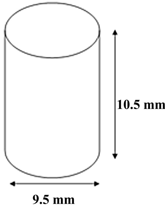
Figure 2. Cylindrical specimen for compression tests at high strain rates.
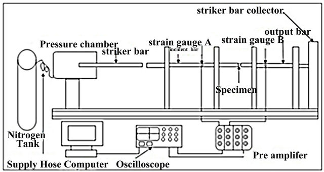
Figure 3. Sketch of the split Hopkinson pressure bar system.
on the elastic wave theory. The deformed specimen that had been subjected to dynamic loading was subjected to metallographic preparation using 0.2% nital as the etching reagent and observed under optical and scanning electron microscope.
3. Constitutive Model
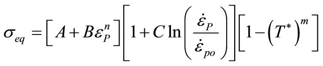
Adiabatic shear bands are formed by localized plastic deformation that depends on the strain rate. Thus for adequate modeling of the formation of ASBs, a rate-dependent constitutive model must be used [5]. The Johnson Cook model [21] relates the three mechanisms that are responsible for the development of ASBs in materials that experience dynamic loading (i.e., work hardening, strain rate hardening, and thermal softening). The main advantage of this model is that it is relatively easy to calibrate with minimum of experimental data in the form of stress-strain curves at different strain rates and temperatures [24]. The Johnson Cook model assumes that the slope of the flow stress curve is independently affected by strain hardening, strain rate sensitivity, and thermal softening behaviors and is given as:
 (1)
(1)
where
 (2)
(2)
Equations (1) and (2),  is the equivalent flow stress, T* is the homologous temperature, Tmelt is the melting temperature of the material and Troom is the room temperature. The equivalent plastic strain is represented by
 , strain rate by
  and the user defined reference accumulative plastic strain rate as
 . The constant parameter terms A, B, C, n, and m are fitted to the data obtained by several tests conducted at low strains and strain rates and at room temperature in a SHPB test [25]. These tests can be conducted at temperatures up to 600˚C and strain rates up to 5000 s‒1. Table 1 shows the Johnson Cook model parameters for AISI 4340 steel from [26] that were used in the simulation.
4. Finite Element Modeling and Simulation
The Johnson Cook constitutive model described in Section 3 is utilized in ABAQUS 6.10 finite element software to model the formation of ASBs in AISI 4340 steel.
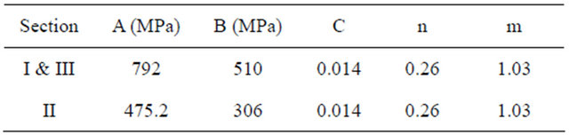
The cylindrical steel specimen shown in Figure 2 is subjected to compressive force in the form of an impact velocity which is a function of the strain rate. In order to model the initiation and growth of ASBs, the cylindrical specimen was divided into three sections i.e. I, II and III as shown in Figure 4. Section II refers to the regions where the possibility of formation of shear bands is high based on experimental observation. The initial yield strength (A) and strain hardening factor (B) for Section III were 60% of the values defined for Sections I and III. This is based on the fact that material flaws such as micro structural defects, known as initial perturbation, result into failure of materials [27]. The parametric solutions for the initiation of ASBs have shown that the total effective perturbation of the materials tested is obtained by summing the strength, temperature and wall thickness components [28]. The critical strain at which the stress collapse occurs also depends logarithmically on the value of the initial perturbation [29]. Also previous research has shown that differences in properties and microstructure cause adiabatic shear bands to form in a material [30]. Local defects and inhomogeneities inside the material act as preferential sites for shear band initiation. Thus, the difference in material properties in the three sections of the cylindrical steel sample used for this study is modeled as a material defect. A 3-dimensional modeling space of deformable type was used in constructing the model in ABAQUS. The material properties corresponding to the different sections making up the cylindrical specimen are stated in Table 2.
An accumulative plastic strain rate of 1677 s‒1 for AISI 4340 steel was used during simulation as the rate at which compressive loading was applied to test specimen and the Poisson ratio of the specimen is 0.33. Impact load was initially applied in the form of a projectile weighing 1.905 kg and moving at a velocity of 17 m/s. The simulation was performed using ABAQUS explicit solver based on the dynamic form of the compressive load. The explicit dynamics procedure performs a large
Table 1. Johnson Cook model parameters [26].
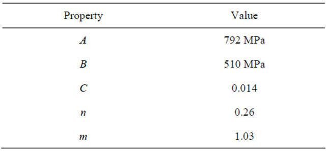
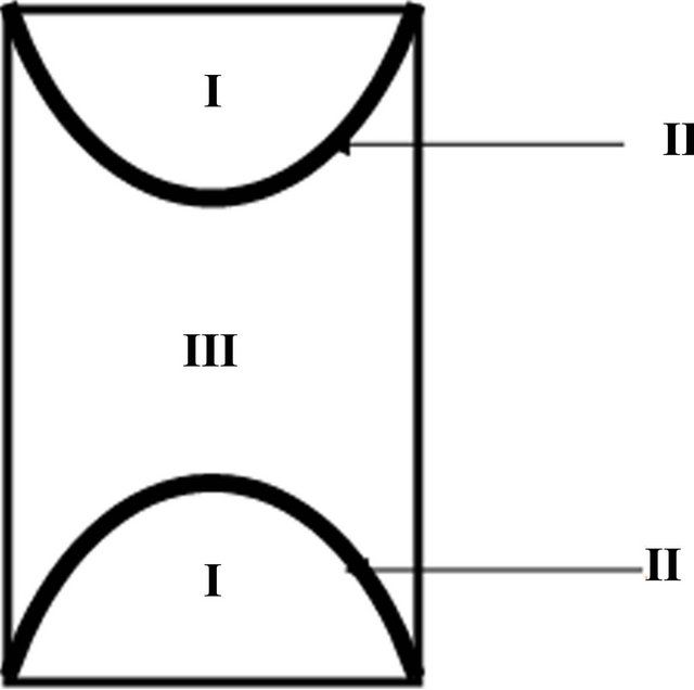
Figure 4. Schematic representation of AISI 4340 model.
Table 2. Johnson Cook parameters utilized in simulation.
number of small time increment iterations efficiently and hence suitable for the simulation. A stress-free state was defined as the initial condition since the deformation is to be accounted for from the initial point of impact and dynamic explicit step was utilized during simulation. The bottom boundary of the finite element network was fixed since its cross-section is a symmetric plane during deformation. Sections I & III were discretized using a global seed size of 1.1 while Section II was discretized using a global seed size of 0.6. The difference in the discretization of the parts is based on the fact that understanding of stress distribution in Section II is of great importance in this study.
5. Results and Discussion
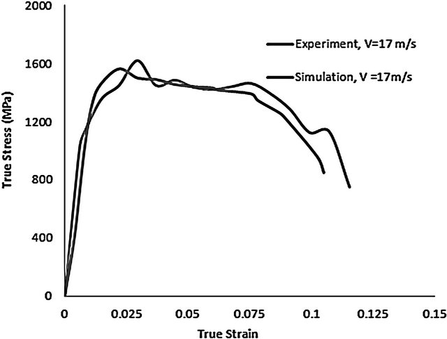
Simulation results show strain localization in the steel specimen in Section II and this shows that ASB is more likely to initiate in Section II. This observation can be justified based on the fact that lower yield strength was declared for Section II. The result of this simulation shows that material defect such as impurity or inhomogeneity could contribute to the growth of an adiabatic shear band in a specimen which is under compressive load. This observation further confirms previous results in literature showing the effect of material inhomogeneity on the failure of materials under dynamic loads [2]. For the simulation performed at an impact velocity of 17 m/s, it was observed that the maximum flow stress in the localized Section II is 1563 MPa (see Figure 5(a)). The path of maximum flow stress of 1563 MPa has a thickness of about 600 µm and is the region where the probability for formation of adiabatic shear band is highest. Experimental result in Figure 5(a) shows that the maximum flow stress which is experienced in the steel specimen when it is impacted at a velocity of 17 m/s was 1620 MPa. The percentage deviation of the simulation results from the experimental result being about 3.64%. Considering the influence of dispersion of shear waves in the split Hopkinson pressure bar and slip effect during experiment, the difference between the maximum flow stresses obtained from the simulation and experimental results can be justified.
The influence of impact velocity on the initiation and growth of ASBs was also studied in this work. Figure 5(b) indicates the result obtained for simulation performed at a velocity of 19 m/s. The constitutive model parameters, used at the velocity of 19 m/s, were the same
 (a)
(a)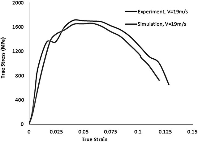 (b)
(b)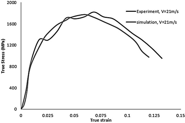 (c)
(c)
Figure 5. (a)-(d) Experimental and numerical stress vs. strain curves obtained during loading of AISI 4340 steel at various velocities.
as those at the velocity of 17 m/s. From Figure 5(b), the maximum flow stress experienced by the steel sample in Section II (which corresponds to region of lower yield strength) is 1659 MPa for the impact velocity of 19 m/s. A maximum flow stress of 1709 MPa was observed during experiment performed at an impact velocity of 19 m/s. The percentage error deviation of the simulation results from the experimental result being about 3.01%. A maximum flow stress of about 1773 MPa was observed in Section II for the simulation performed at an impact velocity of 21 m/s. The maximum flow stress observed within the steel material during experimental test at a velocity of 21 m/s was 1821 MPa. This means that there exists a 2.7% error deviation of the simulation and experimental results. From Figure 5, it can be seen that at the beginning of the stress vs. strain curves, strain hardening dominates the plastic deformation until a maximum flow stress is reached. After the maximum flow stress, thermal softening dominates the deformation process. The rapid stress collapse as a result of mechanical instability is due to intense adiabatic heating along the narrow path that leads to strain localization. The strain corresponding to this stress collapse is the critical strain for the occurrence of the adiabatic shear band. Figure 5 also shows that as the impact velocity increases, the critical strain and time at which thermo-mechanical instability occurs also increases. It has also been observed that as the impact velocity or strain rate increases, maximum flow stress increases. Lee and Lin [31] suggested that as the strain rate increases, the stress increases at any specific strain.
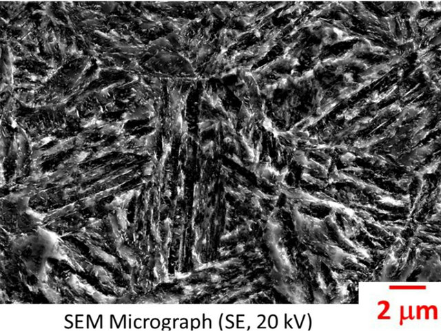
Figure 6 shows the optical and scanning electron micrographs of the original AISI 4340 steel after the heat treatment procedure before impact test. Secondary electrons under an accelerated voltage of 20 kV were used in the scanning electron microscopy. The AISI 4340 steel austenitized at 850˚C, oil-quenched, and tempered at 315˚C consists of martensitic plates and retained austenite. Figure 7 shows the optical micrograph of AISI 4340 steel that was impacted at 17 m/s. It is evident from the figure that adiabatic shear band is formed along the marked curve pathon the transverse cross section of the cylindrical specimens of the AISI 4340 steel. The alloying
 (a)
(a)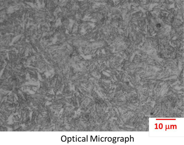 (b)
(b)
Figure 6. Optical micrograph of AISI 4340 steel specimens before impact test.
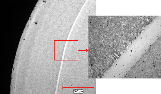
Figure 7. Optical micrograph of cylindrical specimen of AISI 4340 steel impacted at 17 m/s.
elements such as Mo, Cr, Ni, and Mn in the steel sample also increase the tendency for the formation of carbide particles in the steel material which may also act as initial perturbations and thus increase the susceptibility of the steel materials to shear localization. Figure 8 shows the optical micrograph of a crack along the transformed adiabatic shear bands for the steel after the impact at 19 m/s. It is observed that failure and fracture occur along the transformed band. Both ductile and cleavage fracture on the fracture surface of the bulk material for AISI 4340 steel specimens have been reported in literature [12]. Figure 9 shows the optical macrographs of fractured cylindrical AISI 4340 steel specimens. This picture was taken using a stereomicroscope. The specimen eventually fragments into two symmetrical parts, as shown in Figure 9.
6. Conclusion
Experiments have been conducted to determine the initiation and growth of adiabatic shear bands in steel materials that undergo dynamic impact loads. Finite element simulation of the cylindrical specimen of AISI 4340 steel sample was performed using Abaqus 6.10. Results show that region of lower yield strength and strain hardening factor experienced more strain localization and hence higher possibility of failure. Hence, an adiabatic shear band can initiate and grow due to material defect. Simulation was also performed at different impact velocities in order to determine the influence of varying impact
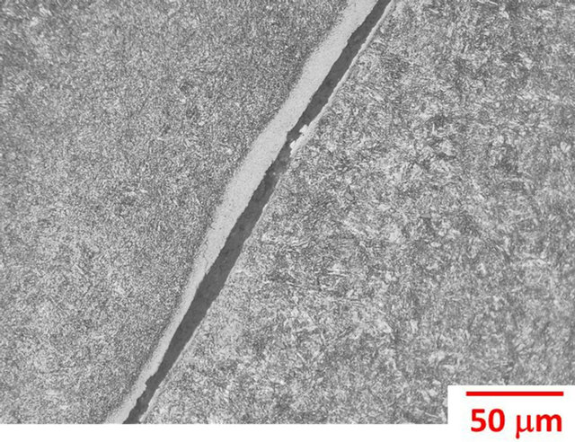
Figure 8. Optical micrograph showing cracks along a white etching band for martensitic AISI 4340 steel impacted at 19 m/s.
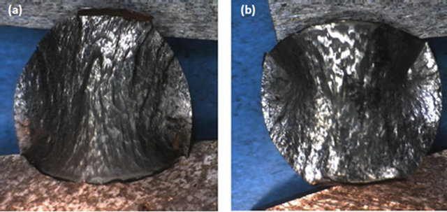
Figure 9. Optical macrographs of fractured cylindrical specimen of martensitic AISI 4340 steel.
velocity on the growth of adiabatic shear band. Simulation results show that at the beginning of the stress vs. strain curve, strain hardening dominates the plastic deformation until a maximum flow stress is reached. After the maximum flow stress, thermal softening dominates the deformation process. The rapid stress collapse as a result of mechanical instability is due to intense adiabatic heating along the narrow path that leads to strain localization which was also observed in the experimental results. Cracks were initiated and propagated along transformed bands leading to fragmentation under the impact load. The susceptibility of the adiabatic shear bands to cracking is markedly influenced by strain rates.
7. Acknowledgements
The authors are grateful for the support provided by the Department of Defense (DoD) through the research and educational program for HBCU/MSI (contract #W911- NF-12-1-061) monitored by Dr. Larry Russell (Program Manager, ARO).
REFERENCES
- A. G. Odeshi and M. N. Bassim, “High Strain-Rate Fracture and Failure of High Strength Low Alloy Steel in Compression,” Materials Science and Engineering: A, Vol. 525, No. 1-2, 2009, pp. 96-101. doi:10.1016/j.msea.2009.07.026
- H. Feng and M. N. Bassim, “Finite Element Modeling of the Formation of Adiabatic Shear Bands in AISI 4340 Steel,” Materials Science and Engineering: A, Vol. 266, No. 1-2, 1999, pp. 255-260. doi:10.1016/S0921-5093(99)00026-X
- S. Kuriyama and M. A. Meyers, “Numerical Modeling of the Propagation of an Adiabatic Shear Band,” Metallurgical Transactions, Vol. 17, No. 3, 1986, pp. 443-450.
- A. G. Odeshi, M. N. Bassim and S. Al-Ameeri, “Effect of Heat Treatment on Adiabatic Shear Bands in a HighStrength Low Alloy Steel,” Materials Science and Engineering: A, Vol. 419, No. 1-2, 2006, pp. 69-75. doi:10.1016/j.msea.2005.11.059
- T. C. Lee, L. C. Chan and B. J. Wu, “Straining Behaviour in Blanking Process-Fine Blanking vs. Conventional Blanking,” Journal of Materials Processing and Technology, Vol. 48, No. 1-4, 1995, pp. 105-111. doi:10.1016/0924-0136(94)01639-I
- V. F. Nesterenko, M. A. Meyers and H. C. Chen, “Shear Localization in High Strain Rate Deformation of Granular Alumina,” Acta Materialia, Vol. 44, No. 5, 1996, pp. 2017-2026.
- C. J. Shih, M. A. Meyers and V. F. Nesterenko, “High Strain-Rate Deformation of Granular Silicon Carbide,” Acta Materialia, Vol. 46, No. 11, 1998, pp. 4037-4065. doi:10.1016/S1359-6454(98)00040-8
- K. Ravi-chandar, J. Lu, B Yang and Z Zhu, “Failure Mode Transition in Polymers under High Strain Rate Loading,” International Journal of Fracture, Vol. 101, No. 1-2, 2000, pp. 33-72.
- M. N. Bassim and A. G. Odeshi, “Shear Strain Localization and Fracture in High Strength Structural Materials,” Materials Science and Engineering, Vol. 31, No. 2, 2008, pp. 69-74.
- S. E. Schoenfeld and T. W. Wright, “A Failure Criterion Based on Material Instability,” International Journal of Solids and Structures, Vol. 40, No. 12, 2003, pp. 3021- 3037. doi:10.1016/S0020-7683(03)00059-3
- K. M. Cho, S. Lee, S. R. Nutt and J. Duffy, “Adiabatic Shear Band Formation during Dynamic Torsional Deformation of an HY-100 Steel,” Acta Metallurgica et Materialia, Vol. 41, No. 3, 1993, pp. 923-932. doi:10.1016/0956-7151(93)90026-O
- Q. Xue and G. T. Gray, “Development of Adiabatic Shear Bands in Annealed 316L Stainless Steel. Part II. TEM Studies of the Evolution of Microstructure during Deformation Localization,” Metallurgy and Materials Transaction: A, Vol. 37, No. 8, 2006, pp. 2447-2458. doi:10.1007/BF02586218
- K. C. Dao and D. A. Schockey, “A Method for Measuring Shear-Band Temperatures,” Journal of Applied Physics, Vol. 50, No. 12, 1979, pp. 8244-8246. doi:10.1063/1.325926
- M. A. Meyers and C. L. Wittman, “Effect of Metallurgical Parameters on Shear Band Formation in Low-Carbon Steels,” Materials Science and Engineering: A, Vol. 21, No. 12, 1990, pp. 3153-3164.
- L. Zener and J. H. Hollomon, “Effect of Strain Rate upon Plastic Flow of Steel,” Journal of Applied Physics, Vol. 15, No. 1, 1944, pp. 22-32. doi:10.1063/1.1707363
- J. Barry and G. Byrne, “TEM Study on the Surface White Layer in Two Turned Hardened Steels,” Materials Science and Engineering: A, Vol. 325, No. 1-2, 2002, pp. 356-364. doi:10.1016/S0921-5093(01)01447-2
- Z. H. Chen, L. C. Chan, T. C. Lee and C. Y. Tang, “An Investigation on the Formation and Propagation of Shear Band in Fine Blanking Process,” Journal of Materials Processing Technology, Vol. 138, No. 1-3, 2003, pp. 610- 614. doi:10.1016/S0924-0136(03)00141-9
- M. A. Meyers, Y. J. Chen, F. D. S. Marquis and D. S. Kim, “High Strain Rate Behaviour of Tantalum,” Metallurgical and Materials Transactions, Vol. 26A, 1995, pp. 2493-2509.
- J. F. C. Lins, H. R. Z. Sandim, H. J. Kestenbach, D. Raabe and K. S. Veechio, “A Microstructural Investigation of Adiabatic Shear Bands in an Interstitial Free Steel,” Materials Science and Engineering: A, Vol. 457, No. 1-2, 2007, pp. 205-218. doi:10.1016/j.msea.2006.12.019
- R. W. Armstrong and F. J. Zerilli, “Dislocation Mechanics Aspects of Plastic Instability and Shear Banding,” Mechanics of Materials, Vol. 17, No. 2-3, 1994, pp. 319- 327.
- G. R. Johnson and W. H. Cook, “A Constitutive Model and Data for Metals Subjected to Large Strains, High Strain Rates and High Temperatures,” Proceedings of the 7th International Symposium on Ballistics, The Hague, 19-21 April 1983, pp. 541-547.
- R. J. Clifton, J. Duffy, K. A. Hartley and T. G. Shawki, “On Critical Conditions for Shear Band Formation at High Strain Rates,” Scripta Metallurgica, Vol. 18, No. 5, 1984, pp. 443-448. doi:10.1016/0036-9748(84)90418-6
- G. T. Gray, “Classic Split Hopkinson Pressure Bar Testing,” ASM Handbook, Vol. 8, 2000, pp. 462-476.
- F. H. Abed, “Physically Based Multiscale-Viscoplastic Model for Metals and Steel Alloys: Theory and Computation,” Ph.D. Thesis, Louisiana State University and Agricultural and Mechanical College, 2005.
- T. Ozel and Y. Karpat, “Identification of Constitutive Model Parameters for High Strain Rate Metal Cutting Conditions Using Evolutionary Computational Algorithms,” Materials and Manufacturing Processes, Vol. 22, No. 5, 2007, pp. 659-667. doi:10.1080/10426910701323631
- T. Ozel and F. Pfefferkon, “Pulsed Laser Assisted Micromilling for Die/Mold Manufacturing,” ASME International Conference on Manufacturing Science and Engineering, Atlanta, 15-18 October 2007, pp. 337-342.
- E. Cepus, C. D. Liu and M. N. Bassim, “The Effect of Microstructure on the Mechanical Properties and Adiabatic Shear Band Formation in a Medium Carbon Steel,” Journal Physique, Vol. 4, No. C8, 1994, p. 553.
- T. W. Wright, “Approximate Analysis for the Formation of Adiabatic Shear Bands,” Journal of the Mechanics and Physics of Solids, Vol. 38, No. 4, 1990, pp. 515-530. doi:10.1016/0022-5096(90)90012-S
- A. Molinari and R. J. Clifton, “Analytical Characterization of Shear Localization in Thermoviscoplastic Materials,” Journal of Applied Mechanics, Vol. 54, No. 4, 1987, pp. 806-812. doi:10.1115/1.3173121
- M. N. Bassim, “Study of the Formation of Adiabatic Shear Bands in Steels,” Journal of Materials Processing Technology, Vol. 119, No. 1-3, 2001, pp. 234-234. doi:10.1016/S0924-0136(01)00952-9
- W. S. Lee and C. F. Lin, “Impact Properties and Microstructure Evolution of 304L Stainless Steel,” Materials Science and Engineering: A, Vol. 308, No. 1-2, 2001, pp. 124-135. doi:10.1016/S0921-5093(00)02024-4
NOTES
*Corresponding author.