Soft Nanoscience Letters
Vol.2 No.3(2012), Article ID:19817,8 pages DOI:10.4236/snl.2012.23009
Effect of Camphor Sulfonic Acid Doping on Structural, Morphological, Optical and Electrical Transport Properties on Polyaniline-ZnO Nanocomposites
![]()
1Materials Research Laboratory, School of Physical Sciences, Solapur University, Solapur, India; 2Crystal Technology Section, Technical Physics Division, Bhabha Atomic Research Centre (BARC), Mumbai, India.
Email: *drvbpatil@gmail.com
Received April 17th, 2012; revised May 24th, 2012; accepted June 4th, 2012
Keywords: Polyaniline; Zinc Oxide; XRD; SEM; FTIR; UV-Vis
ABSTRACT
In the present work, we report on effect of camphor sulfonic acid (CSA) doping on polyaniline-ZnO (50%) nanocomposites prepared by spin coating method on glass substrates. The XRD analysis revealed that the addition of CSA has no effect on crystallinity of PANi-ZnO nanocomposites. Surface morphological studies (SEM) showed that CSA has a strong effect on morphology of PANi-ZnO. The FTIR & UV-Vis spectroscopy confirmed the interaction between CSA and PANi-ZnO nanocomposite. DC electrical conductivity studies showed an increase in conductivity of PANi-ZnO nanocomposites by one order due to addition of CSA (10% - 50%).
1. Introduction
Semiconducting zinc oxide (ZnO) is attracting lot of attention due to its unique properties such as direct wide band gap (3.37 eV) and large exciton binding energy (60 meV) at room temperature [1]. Due to these properties it has been studied extensively for making optical and electronic devices [1-3] like: light emitting diodes, solar cells, transducers, varistors, photodetetors, etc. Nanostructured ZnO can be synthesized by various methods such as physical, chemical, electrochemical, etc. but chemical route has attracted much attention due to the flexibility of controlling the shape and size of the structures by tuning the different growth conditions [4-10].
In recent years, the development of inorganic/polymer hybrid materials on nanometer scale have been receiving significant attention due to a wide range of potential applications in optoelectronic devices [11-13] and in field effect transistors [14]. The inorganic fillers at nanoscale exhibit high surface to volume ratio and thus expected to modify drastically the electrical, optical and dielectric properties of polymer. In general, the synthesis of hybrid of polymer/inorganic material has the goal of obtaining a new composite material having synergetic or complementary behaviors between the polymer and inorganic material. Polyaniline (PANi) is a most studied polymer because of its relative ease in preparation, good environmental stability [15,16] and tunable conductivity. Several reports on the synthesis of composite of nanofillers like: TiO2, CdS, Na+-montmorillonite, Pd and Au with PANi have been demonstrated [17-21]. These synthesis processes have been carried out either in the aqueous solutions or via a sol-gel method, including the initial dispersion of the nanoparticles in the solution and the succedent oxidative polymerization of aniline with ammonium peroxidisulphate (APS). Since the conducting polyaniline and inorganic semiconducting material ZnO in nanoform both are having a wide range of technological applications, we got motivated to make composite of PANi and ZnO and believed to get novel properties resulting from the molecular level interaction of these two dissimilar chemical components [22,23].
In most of these cases, the nanocomposites were further used in various applications in their thin-film form. Although these PANi-ZnO nanocomposites are also conducting since they are polyaniline emeraldine chloride, their processability is still poor to limit their commercial uses although their conductivity could be measured by sandwiching the pellets. PANi doped with organic acids such as CSA, DBSA, PVSA etc. which possesses sufficiently strong Bronsted acid centers capable of polyaniline protonation together with suitable functional groups which, when introduced to the polymer matrix upon doping, induce the solubilization of its stiff conjugated backbone, is readily soluble, chemically stable, and electrically conductive [24-27].
There are few reports on the synthesis, morphological, electrical and optical studies [28,29] of PANi/ZnO composite. However to the best of our knowledge no study has been reported on effect of organic (ionic) acid doping on PANi/ZnO nanocomposite.
In this paper for the first time, we report systematic investigation on the effect of camphor sulfonic acid (CSA) doping on structural, morphological optical and electrical properties of PANi-ZnO nanocomposite. Much effort has been put into the investigation of the interaction between CSA and PANi-ZnO in order to gain a better understanding of the doping effect of CSA. The structural, morphological, optical and electrical properties of CSA doped PANi-ZnO nanocomposite were investigated using XRD, FTIR, SEM, UV-Vis spectroscopy and four probe technique.
2. Experimental Techniques
2.1. Synthesis of PANi-ZnO Nanocomposite
The undoped polyaniline powder was dissolved in mcresol. The solution was stirred for 11 hr and filtered with a Whatman filter paper having pores of size of few microns. The solution of filtered undoped PANi was poured in a Petri dish and dried at 60˚C [30]. The ZnO nanoparticles were prepared by sol gel method [31]. The ZnO nanocomposite with undoped PANi was prepared by adding 50 wt% ZnO nanoparticles in filtered solution of undoped PANi in m-cresol and stirring it for 11 hr. Films of the nanocomposite were prepared on glass substrate by spin coating method at 3000 rpm for 40 s [32].
2.2. Synthesis of CSA Doped PANi-ZnO Nanocomposite
The CSA doped PANi-ZnO nanocomposites were prepared by adding 10 - 50 wt% of camphor sulfonic acid (CSA) into PANi-ZnO nanocomposite powder and grinding it in a smooth agate and mortar for 1 hr for solid state doping. Thin films of the CSA doped PANi-ZnO (50%) nanocomposite were prepared on glass substrate by spin coating technique at 3000 rpm for 40 s and dried on hot plate at 100˚C for 10 min.
Figure 1 shows the flow diagram of preparation of CSA doped PANi-ZnO nanocomposite.
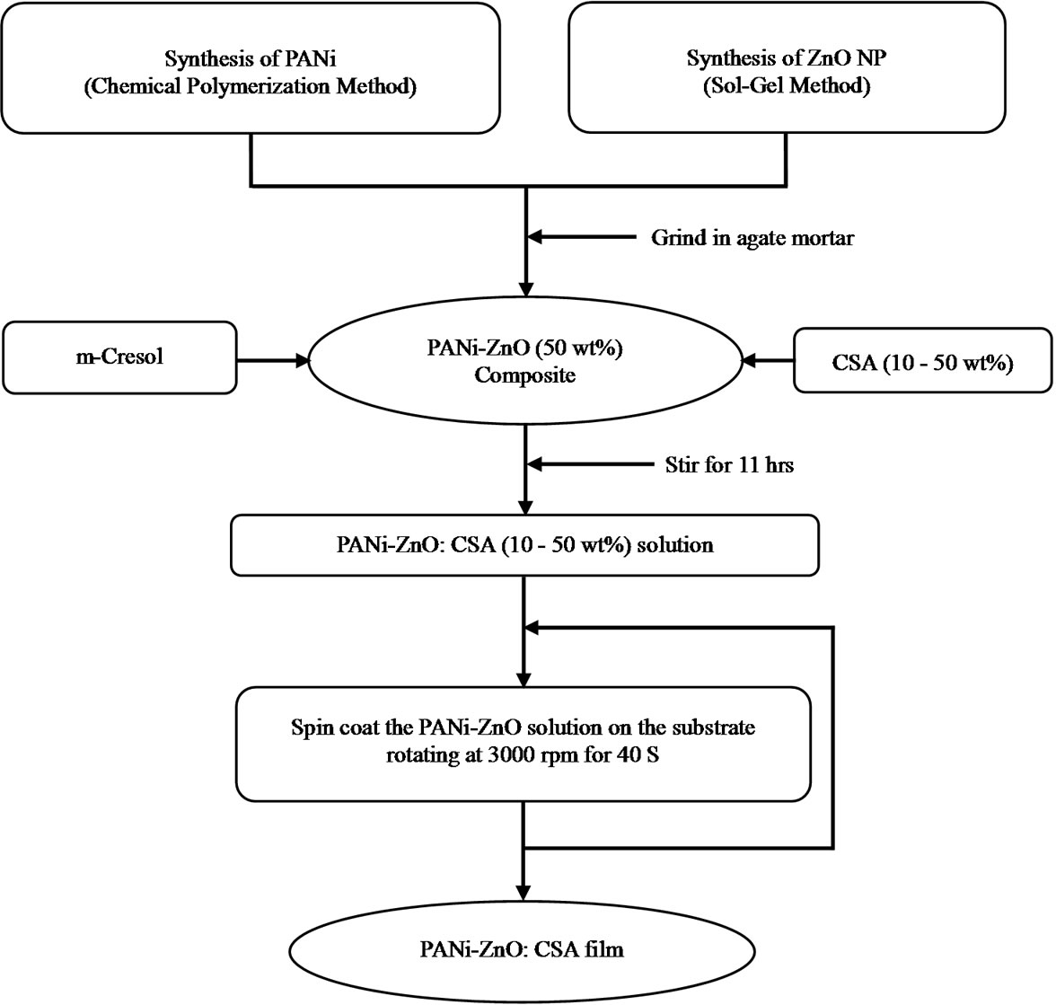
Figure 1. Flow diagram of preparation of PANi-ZnO:CSA (10 - 50 wt%).
2.3. Characterization Techniques
X-ray diffraction (XRD) studies were carried out using a Philips powder X-ray diffractometer (Model: PW1710). The XRD patterns were recorded in the 2θ range of 10˚ - 80˚ with step width 0.02˚ and step time 1.25 sec using CuKα radiation (λ = 1.5406 Å). The XRD patterns were analyzed by matching the observed peaks with the standard pattern provided by JCPDS file. Fourier Transform Infra Red (FTIR) spectroscopy (Model: Perkin Elmer 100) of CSA doped PANi-ZnO (50%) nanocomposite was studied in the frequency range of 400 - 4000 cm−1. Morphological study of the films of CSA doped PANiZnO nanocomposite was carried out using scanning electron microscopy (SEM Model: JEOL JSM 6360) operating at 20 kV. UV-Vis spectra of the CSA doped PANiZnO nanocomposite, which were dispersed in m-cresol under ultrasonic action, were recorded on a Simandzu- 100 UV-Vis spectrophotometer. The electrical dc resistivity measurements were made on thin films using four probe technique. The thickness of the film was measured by using a Dektak profilometer. The values obtained are presented in Table 1.
3. Results and Discussion
3.1. Structural Analysis
Figure 2 shows the X-ray diffraction pattern of the CSA doped (10% - 50%) PANi-ZnO nanocomposite.
The spectra showed sharp and well defined peaks, indicating the crystallinity of synthesized materials. The peak at 2θ = 25.30 corresponds to (110) plane of PANi [30]. Other observed 2θ values are consistent with the standard JCPDS values (JCPD File No.79-0208) which shows wurtzite structure of ZnO [32]. However, the peaks at 2θ = 11.24, 18.66 and 19.32 in the crystal pattern of PANi-ZnO:CSA belong to CSA and their strength is found to be increasing with increasing wt% of CSA in PANi-ZnO nanocomposites [33]. They are more significant in the 40 wt% and 50 wt% doping patterns. The peaks at 2θ = 15.22, 21.18 and 27.4 (d = 5.82, 4.19 and 3.26 Å respectively), belong to the crystal structure of PANi [34]. These results indicate the effect of camphor sulfonic acid doping on structural properties of PANi-ZnO nanocomposites.
3.2. Fourier Transform Infrared Spectroscopy Studies
The FTIR spectra of PANi-ZnO:CSA (10% - 50%) are as shown in figure 3.
Actual spectra was recorded in the wave number range 400 - 4000 cm−1, however figure shows only expanded view in wave number region 500 - 2000 cm−1, where major changes are observed. The incorporation of CSA into the polymer chain was confirmed from the FTIR studies. The presence of characteristic IR absorption at 1575, 1480, 1294, 1120, and 808 cm−1 (quinoid, benzenoid and Zn-O-Zn) in PANi-ZnO spectrum [32] is found to shift towards higher frequency side at 1586, 1494, 1298, 1139 and 820 cm−1 respectively [35-37]. These shifts
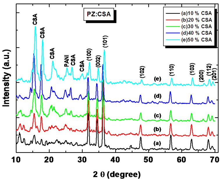
Figure 2. X ray diffraction patterns of (a) PANi-ZnO:CSA (10%); (b) PANi-ZnO:CSA (20%); (c) PANi-ZnO:CSA (30%); (d) PANi-ZnO:CSA (40%) and (e) PANi-ZnO:CSA (50%).

Table 1. Effect of CSA doping on thin film properties PANi-ZnO nanocomposite.
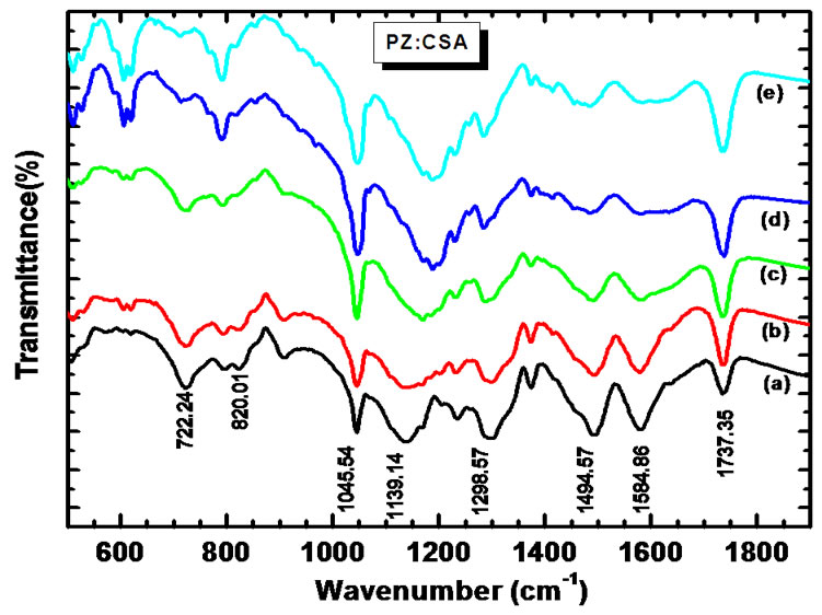
Figure 3. FTIR spectra of (a) PANi-ZnO:CSA (10%); (b) PANi-ZnO:CSA (20%); (c) PANi-ZnO:CSA (30%); (d) PANi-ZnO:CSA (40%) and (e) PANi-ZnO:CSA (50%).
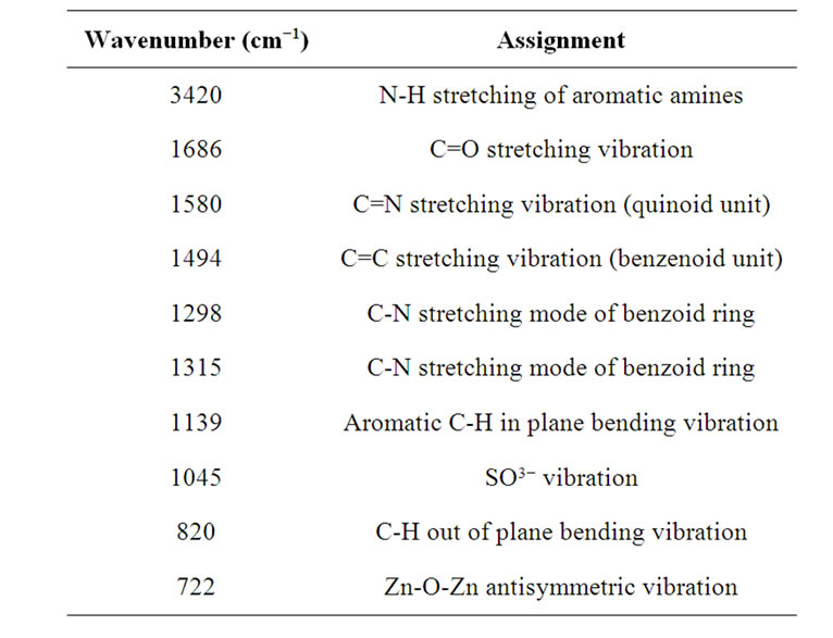
Table 2. Characteristic frequencies of CSA doped PANiZnO nanocomposite.
can be attributed to the interaction of CSA with PANiZnO nanocomposite. Two more peaks at 1045 cm−1 (SO3−) and 1737 cm−1 (C=O) [38] are also observed. The fact that the polymer is protonated in part by surface anions is demonstrated by the presence of the peak at 722 cm−1, which is attributed to a stretching vibration in the surface anion [39]. The frequency data obtained and their assignments are presented in Table 2.
3.3. Surface Morphology Studies
Figure 4 shows the surface morphologies of PANi-ZnO: CSA (10 - 50 wt%). The change in the surface morphology has been observed with increasing composition of CSA (10% - 50%) in PANi-ZnO nanocomposite (Figures 4(a)-(e)). The complex, stringy, interconnected network is a general feature of the morphology of CSA doped PANi (EB)-ZnO nanocomposite. At higher % of CSA, the connected path way become more and more dense as the pure PANi-ZnO is approached [32]. At these higher percentage of CSA doped PANi-ZnO nanocomposites; the morphology appears almost foam like with PANi-ZnO network surrounded by CSA. Thus CSA provides large conduction island thereby reducing the conduction path through the film. The increase in conductivity of PANi-ZnO:CSA thin films may be devoted to this phenomenon.
3.4. UV-Vis Analysis
The effect of addition of CSA in PANi-ZnO nanocomposite was studied using UV-vis spectroscopy. UV-vis spectra of PANi, PANi-ZnO and PANi-ZnO:CSA (50 wt%) suspension in m-cresol is as shown in Figure 5.
It shows that three characteristic bands of PANi appear at about 341, 416 and 924 nm, which can be attributed to the π-π*, polaron-π* and π-polaron transition respectively [35-38]. It can be noted that all of the characteristic peaks of ZnO and PANi (EB) appear in PANi-ZnO composite, but there are some shifts compared with PANi. The peaks at 441 and 924 nm are slightly shifted towards lower wavelength side (435 and 869 nm) respectively [38]. In case of PANi-ZnO:CSA (50%) also the same shifting towards the lower wavelength side is observed. The peaks observed in PANi-ZnO at 334 and 435 nm are shifted to 301 and 380 nm respectively. The shifting of the bands in the spectra of PANi-ZnO indicates that CSA interacts strongly with PANi-ZnO and has the effect of doping on PANi-ZnO nanocomposite. However UV spectra of PANi-ZnO:CSA (50%) exhibit the flat peak at 824 nm followed by free carrier tail indicates that the localized polaron band is converted to the delocalized polaron free carrier tail absorption. Such difference also supports the high conductivity of PANi-ZnO: CSA (50%) [39].
3.5. Electrical Conductivity Studies
Figure 6 shows the variation of electrical conductivity (σ) with increasing doping concentration of CSA into PANiZnO measured according to the standard four point probe method at room temperature.
It is observed that the room temperature conductivity of PANi-ZnO increases remarkably from 7.24 × 10⁻⁶ S/cm to 2.68 × 10⁻⁵ S/cm as doping concentration of CSA increased from 0 - 10 wt% (Table 1). The conductivity continues to increase further with increasing CSA content into PANi-ZnO but at the slower rate. This may be attributed to the doping effect of CSA which maximizes the number of carriers. The highest number of carriers can be connected with the delocalization effect of
 (a)
(a) (b)
(b)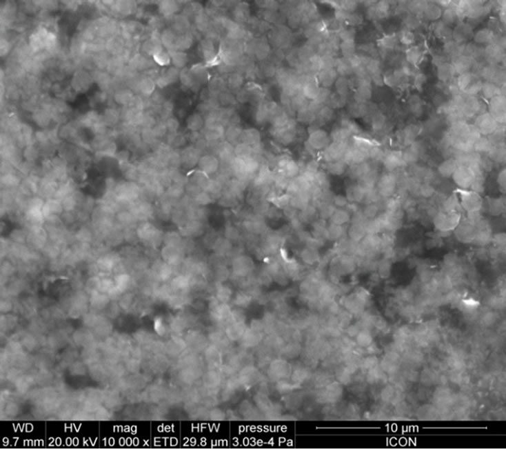 (c)
(c)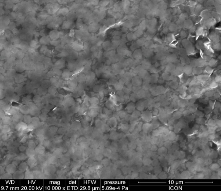 (d)
(d)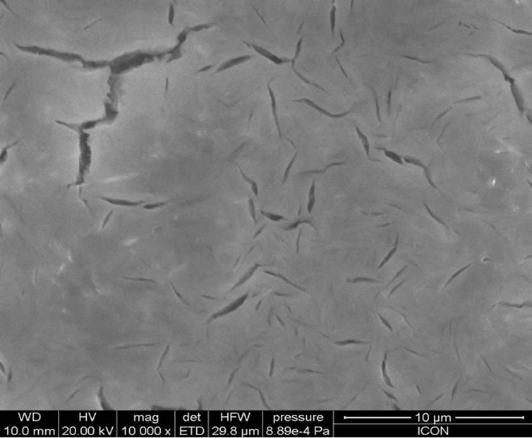 (e)
(e)
Figure 4. SEM micrographs: (a) PANi-ZnO:CSA (10%); (b) PANi-ZnO:CSA (20%); (c) PANi-ZnO:CSA (30%); (d) PANiZnO: CSA (40%) and (e) PANi-ZnO:CSA (50%).
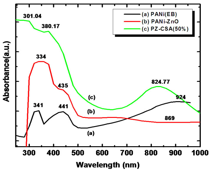
Figure 5. UV-Vis spectra of CSA doped PANi-ZnO nanocomposites.
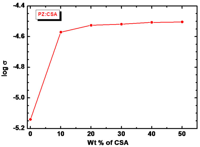
Figure 6. Variation of log σ versus the content of CSA in PANi-ZnO nanocomposites.
doping process and formation of the polarons or bipolarrons in the composite structure as discussed before by researchers [40,41], thus enhancing the conductivity of composite. Moreover, CSA being anionic surfactant [42] may prevent agglomeration of functional material and provide reduced conduction path through the film. This can also be one of the reasons of remarkable increase in electrical conductivity due to CSA doping. The saturation of the conductivity at higher doping percentages (30 - 50 wt%) of CSA may possibly due to combination of CSA coated ZnO with CSA doped PANi induces the confirmation change of stiff PANi backbone due to contacted CSA coated ZnO. The saturation in increase in conductivity may be due to particle blockage of conduction path by the ZnO nanoparticles embedded in the PANi matrix [43].
4. Conclusion
The doping effect of CSA on structural, morphological optical and electrical properties of PANi-ZnO nanocomposite was investigated by XRD, FTIR, SEM, UV-Vis spectroscopy and four probe technique. The XRD spectra showed that the addition of CSA has no effect on crystallinity of PANi-ZnO nanocomposites. SEM studies revealed that the connected path way become more and denser as % of CSA increased in PANi-ZnO nanocomposites. The FTIR spectra reveal the interaction between CSA and PANi-ZnO nanocomposite. Electrical conductivity measurements indicate that with the increasing content of CSA, the conductivity shows an orderly increase.
5. Acknowledgements
Authors (VBP) are grateful to DAE-BRNS, for financial support through the scheme no.2010/37P/45/BRNS/1442.
REFERENCES
- P. Yang, H. Yan, S. Mao, R. Russo, J. Johnson, R. Saykally, N. Morris, J. Pham, R. He and H. Choi, “Controlled Growth of Zinc Oxide Nanowires and Their Optical Properties,” Advanced Function Materials, Vol. 12, No. 5, 2002, pp. 323-331. doi:10.1002/1616-3028(20020517)12:5<323::AID-ADFM323>3.0.CO;2-G
- W. I. Park, G. Yi, M. Kim and S. L. Pennycock, “ZnO Nanoneedles Non-Catalytic Vapor-Phase Epitaxy,” Advanced Materials, Vol. 14, No. 24, 2002, pp. 1841-1843. doi:10.1002/adma.200290015
- L. Vayssieres, K. Keis, A. Hagfeldt and S. Lindquist, “Three-Dimensional Array of Highly Oriented Crystalline ZnO Microtubes,” Chemistry of Materials, Vol. 13, No. 12, 2001, pp. 4395-4398. doi:10.1021/cm011160s
- C. Pacholski, A. Kornowski and H. Weller, “Selbstorganisation von ZnO: Von Nanopartikeln zu Nanostäbchen,” Angewandte Chemie, Vol. 114, No. 7, 2002, pp. 1234-1237. doi:10.1002/1521-3757(20020402)114:7<1234::AID-ANGE1234>3.0.CO;2-D
- V. B. Patil, S. G. Pawar, S. L. Patil and S. B. Krupanidhi, “ZnO Nanocrystalline Thin Films: A Correlation of Microstructural, Optoelectronic Properties,” Journal of Materials Science: Materials Electronics, Vol. 41, No. 4, 2010, pp. 355-359. doi:10.1007/s10854-009-9920-5
- J. H. Lee, K. H. Ko and B. O. Park, “Electrical and Optical Properties of ZnO Transparent Conducting Films by the Sol-Gel Method,” Journal of Crystal Growth, Vol. 247, No. 1, 2003, pp. 119-125. doi:10.1016/S0022-0248(02)01907-3
- M. A. Chougule, S. L. Patil, S. G. Pawar, B. T. Raut, P. R. Godse, S. Sen and V. B. Patil, “Fabrication of Nanostructured ZnO Thin Film Sensor for NO2 Monitoring,” Ceramic International, Vol. 28, 2012, pp. 2685-2692. doi:10.1016/j.ceramint.2011.11.036
- V. Gupta and A. Mansingh, “Influence of Post-Deposition Annealing on the Structural and Optical Properties of Sputtered Zinc Oxide Film,” Journal of Applied Physics, Vol. 80, 1996, pp. 1063-1073. doi:10.1063/1.362842
- S. L. Patil, S. G. Pawar, A. T. Mane, M. A. Chougule and V. B. Patil, “Nanocrystalline ZnO Thin Films: Optoelectronic and Gas Sensing Properties,” Journal of Materials Science: Materials in Electronics, Vol. 21, No. 12, 2010, pp. 1332-1336. doi:10.1007/s10854-010-0071-5
- L. Vayssieres, K. Keis, A. Hagfeldt and S. Lindquist, “Three-Dimensional Array of Highly Oriented Crystalline ZnO Microtubes,” Chemistry of Materials, Vol. 13, No. 12, 2001, pp. 4395-4398. doi:10.1021/cm011160s
- S. L. Patil, S. G. Pawar, M. A. Chougule, B. T. Raut, P. R. Godse, S. Sen and V. B. Patil, “Structural, Morphological, Optical & Electrical Properties of PANi-ZnO Nanocomposites,” International Journal of Polymeric Materials, in Press. doi:10.1080/00914037.2011.610051
- B. W. J. E. Beek, L. H. Slooff, M. N. Wienk, J. M. Kroon and R. A. J. Janseen, “Hybrid Solar Cells Using a Zinc Oxide Precursor and a Conjugated Polymer,” Advanced Functional Materials, Vol. 15, No. 10, 2005, pp. 1703- 1709. doi:10.1002/adfm.200500201
- X. M. Sui, C. L. Shao and Y. C. Liu, “Photoluminescence Properties of Highly Dispersed ZnO Quantum Dots in Polyvinyl Pyrrolidone Nanotubes Prepared by a Single Capillary Electrospinning,” Applied Physics Letters, Vol. 87, 2005, pp. 113-118.
- D. C. Olson, J. Piris, R. T. Colins, S. E. Shaheen and D. S. Ginley, “Hybrid Photovoltaic Devices of Polymer and ZnO Nanofiber Composites,” Thin Solid Films, Vol. 496, No. 1, 2006, pp. 26-29. doi:10.1016/j.tsf.2005.08.179
- Z. X. Xu, V. A. L. Roy, P. Stallinga, M. Muccini, S. Toffanin, H. F. Xiang and C. M. Che, “High Efficiency Phosphorescent Organic Light-Emitting Diodes Using Carbazole-Type Triplet Exciton Blocking Layer,” Applied Physics Letters, Vol. 90, No. 22, 2007, pp. 223505-223509. doi:10.1063/1.2742788
- G. Gustafsson, Y. Cao, G. M. Treacy, F. Klavetter, N. Colaneri and A. Heeger, “Flexible Light-Emitting Diodes Made from Soluble Conducting Polymers,” Nature, Vol. 357, No. 6378, 1992, pp. 477-479. doi:10.1038/357477a0
- M. J. Sailor, E. J. Ginsburg, C. B. Gorman, A. Kumar, R. H. Grubbs and N. S. Lewis, “Thin Films of n-Si/Poly- (CH3)3Si-Cyclooctatetraene: Conducting-Polymer Solar Cells and Layered Structures,” Science, Vol. 249, No. 4973, 1990, pp. 1146-1149. doi:10.1126/science.249.4973.1146
- X. He and W. Qi, “Ultrasonic irradiation: A Novel Approach to Prepare Conductive Polyaninine/Nanocrystalline TiO2 Composites,” Chemistry of Materials, Vol. 14, 2002, pp. 2158-2165. doi:10.1021/cm0109591
- C. Danielle, S. Michelle, A. Ivo and Z. Aldo,” Preparation and Characterization of Novel Hybrid Materials Formed from (Ti, Sn)O2 Nanoparticles and Polyaniline,” Chemistry of Materials, Vol. 15, 2003, pp. 4658-4665. doi:10.1021/cm034292p
- J. Park, S. Park, A. Koukitu, O. Hatozaki and N. Oyarna, “Electrochemical and Chemical Interactions between Polyaniline and Palladium Nanoparticles,” Synthetic Metals, Vol. 141, No. 3, 2004, pp. 265-269. doi:10.1016/S0379-6779(03)00410-7
- R. Chandrakanthi and M. Careem, “Preparation and Characterization of CdS and Cu2S Nanoparticle/Polyani-Line Composite Films,” Thin Solid Films, Vol. 417, No. 1-2, 2002, pp. 51-56. doi:10.1016/S0040-6090(02)00600-4
- S. Pethkar, R. Patil, J. Kher and K. Vijayarnohanan, “Deposition and Characterization of CdS Nanoparticle/ Polyaniline Composite Films,” Thin Solid Films, Vol. 349, No. 1-2, 1999, pp. 105-109. doi:10.1016/S0040-6090(99)00222-9
- M. Matsumura and T. Ohno, “Concerted Transport of Electrons and Protons across Conducting Polymer Membranes,” Advanced Materials, Vol. 9, No. 4, 1997, pp. 357-359. doi:10.1002/adma.19970090416
- H. Yoneyama, N. Takahashi and S. Kuwabata, “Catalytic Asymmetric Reaction of Lithium Ester Enolates with Imines,” Journal of the Chemical Society, Chemical Communications, Vol. 2, No. 8, 1999, pp. 716-719.
- T. A. Skotheim, R. Elsenbaumer and J. Reynolds, Eds., “Handbook of Conducting Polymers,” Marcel Dekker, New York, 1998.
- B. T. Raut, P. R. Godse, S. G. Pawar, M. A. Chougule, S. Sen, R. C. Pawar, C. S. Lee and V. B. Patil, “Novel Method of Fabrication of Polyaniline-CdS Nanocomposites: Structural, Morphological and Optoelectronic Properties,” Ceramic International, Vol. 38, No. 5, 2012, pp. 3999-4007. doi:10.1016/j.ceramint.2012.01.056
- J. Stejkal, I. Spurina, M. Trchova, J. Prokes, J. Krivka and E. Tobolkova, “Solid State Protonation and Electrical Conductivity of Polyaniline,” Macromolecules, Vol. 31, No. 7, 1998, pp. 2218-2222. doi:10.1021/ma970823h
- S. L. Patil, M. A. Chougule, S. G. Pawar, S. Sen and V. B. Patil, “Development of Polyaniline-ZnO Nanocomposite Gas Sensor,” Sensors and Transducers, Vol. 134, No. 11, 2011, pp. 120-131.
- B. T. Raut, M. A. Chougule, S. R. Nalage, D. S. Dalavi, S. Mali, P. S. Patil and V. B. Patil, “CSA Doped Polyaniline /CdS Organic-Inorganic Nanohybrid: Physical and Gas Sensing Properties,” Ceramic International, 2012, in Press. doi:10.1016/j.ceramint.2012.03.064
- S. G. Pawar, S. L. Patil, M. A. Chougule and V. B. Patil, “Microstructural and Optoelectronic Studies on Polyaniline: TiO2 Nanocomposite,” International Journal of Polymeric Materials, Vol. 60, No. 3, 2011, pp. 244-254. doi:10.1080/00914037.2010.504175
- S. L. Patil, M. A. Chougule, S. G. Pawar, B. T. Raut, S. Sen and V. B. Patil, “New Process for Synthesis of ZnO Thin Films: Microstructural, Optical and Electrical Characterization,” Journal of Alloys and Compounds, Vol. 509, 2011, pp. 10055-10061. doi:10.1016/j.jallcom.2011.08.030
- S. L. Patil, S. G. Pawar, M. A. Chougule, S. Sen and V. B. Patil, “PANi-ZnO Nanocomposites: Synthesis and Characterization,” AIP Conference Proceedings, Vol. 1391, No. 1, 2011, pp. 621-623. doi:10.1063/1.3643629
- C. He, Y. Tan and Y. Li, “Conducting Polyaniline Nanofiber Networks Prepared by the Doping Induction of Camphor Sulfonic Acid,” Journal of Applied Polymer Science, Vol. 87, No. 9, 2003, pp. 1537-1540. doi:10.1002/app.11599
- Y. He, “A Novel Emulsion Route to Sub-Micrometer Polyaniline/Nano-ZnO Composite Fibers,” Applied Surface Science, Vol. 249, 2005, pp. 1-6. doi:10.1016/j.apsusc.2004.11.061
- H. C. Pant, M. K. Patra, S. C. Negi, A. Bhatia, S. R. Vadera and N. Kumar, “Studies on Conductivity and Dielectric Properties of Polyaniline-Zinc Sulphide Composites,” Bulletin of Materials Science, Vol. 29, No. 4, 2006, pp. 379-384. doi:10.1007/BF02704139
- T. K. Sarma and A. Chattopadhyay, “Reversible Encapsulation of Nanometer-Size Polyaniline and PolyanilineAu-Nanoparticle Composite in Starch,” Langmuir, Vol. 20, No. 11, 2004, pp. 4733-4737. doi:10.1021/la0495884
- M. A. Chougule, S. L. Patil, S. G. Pawar, B. T. Raut, P. R. Godse, S. Sen and V. B. Patil, “Facile and Efficient Route for Preparation of Polypyrrole-ZnO Nanocomposites: Microstructural, Optical and Charge Transport Properties,” Journal of Applied Polymer Science, Vol. 125, No. S1, pp. E541-E547. doi:10.1002/app.36475
- E. Konyushenko, J. Stejkal, M. Trchova, J. Hradil, J. Kovarova, J. Prokes, M. Cieslar, J. Y. Hwang, K. H. Chen and I. Sapurina, “Multi-Wall Carbon Nanotubes Coated with Polyaniline,” Polymer, Vol. 47, No. 16, 2006, pp. 5715-5723. doi:10.1016/j.polymer.2006.05.059
- S. L. Patil, M. A. Chougule, S. Sen and V. B. Patil, “Measurements on Room Temperature Gas Sensing Properties of CSA Doped Polyaniline-ZnO Nanocomposites,” Measurement, Vol. 45, No. 3, 2012, pp. 243-249. doi:10.1016/j.measurement.2011.12.012
- Y. P. Maminya, V. V. Davydenko, P. Pissis and E. V. Lebedev, “Electrical and Thermal Conductivity of Polymers Filled with Metal Powders,” European Polymer Journal, Vol. 38, No. 9, 2002, pp. 1887-1897. doi:10.1016/S0014-3057(02)00064-2
- J. C. Huang, “Carbon Black Filled Conducting Polymers and Polymer Blends,” Advances in Polymer Technology, Vol. 21, No. 4, 2002, pp. 299-313. doi:10.1002/adv.10025
- B. T. Raut, M. A. Chougule, S. Sen, R. C. Pawar, C. S. Lee and V. B. Patil, “Novel Method of Fabrication of Polyaniline-CdS Nanocomposites: Structural, Morphological and Optoelectronic Properties,” Ceramics International Journal, Vol. 38, 2012, pp. 3999-4007.
- B. T. Raut, M. A. Chougule and V. B. Patil, “PolyanilineCdS Nanocomposites: Effect of Camphor Sulfonic Acid Doping on Structural, Microstructural, Optical and Electrical Properties,” Journal of Materials Science: Materials in Electronics, 2012, in Press. doi:10.1007/s10854-012-0708-7
NOTES
*Corresponding author.