Journal of Biomaterials and Nanobiotechnology
Vol.4 No.1(2013), Article ID:26844,7 pages DOI:10.4236/jbnb.2013.41005
Effect of the Cavity-Cavity Interaction on the Stress Amplitude in Orthopedic Cement
![]()
LMPM, Mechanical Engineering Department, University of Sidi Bel Abbes, Sidi Bel Abbes, Algeria.
Email: *zouambileila@yahoo.com
Received October 10th, 2012; revised November 20th, 2012; accepted December 13th, 2012
Keywords: Cement; Stress Concentration; Interaction Effect; Cavity; Size
ABSTRACT
The presence of porosities in bone cement (polymethylmethacrylate) in total hip prosthesis (THP) cemented is necessary for the diffusion of antibiotics, but it is a critical characteristic of weakening by the effect of stress concentration and the interconnecting pores. The aim of this study was to analyse by the finite element method (FEM), the size influence of micro-cavities in cement assuming the junction cup-bone, and the effect of cavity-cavity interaction on the stress level and distribution in cement according to the human stance defined by the implant position axis compared to that of the cup.
1. Introduction
PMMA has been the standard product in the orthopaedic industry for decades. It is better in having bone-bonding, bioactive properties, the ability to fill a bone deficiency with greater strength and minimize the load transfer to bone. But one of the problems encountered by experts of cemented arthroplasty is the presence of defects (porosities, inclusions and cracks) in cement whom is the main cause of damage to the binder [1].
The cement allows the distribution of antibiotics. The satisfaction of this last property requires some density of porosities. But in mechanical view may be damaging if these microvoids can locally present at the region of stress concentration producing a possible fracture of cement [2]. The stress intensity factor for crack emanating from microvoid is higher than the ordinary crack. Several studies have analyzed the porosities effect in the cement on its mechanical behavior [1-5]. However, the probability of survival of cemented THP implanted recently is very high. Improved techniques for preparation and placement of cement as well as the methods of realization contribute to this success. Progress remains to be done. Until now, cement fixation of the cup of a total hip prosthesis has been little studied compared to the femoral component.
The main aim of this work is double: the first is to simulate all the porosity to a cavity in cement (coalescence phenomenon) and to analyze by the FEM the stress level in this binder according to the orientation of the implant axis compared to that of the cup. The second is to analyze the effects of intercavities interaction on the mechanical behavior of the cement.
The originality of this work resides not only on the analysis of the size of the cavities, their voluminous fractions but also on the effect of cavity-cavity interaction on the level and distribution of the equivalent stress in orthopedic cement.
2. Materials and Methods
In this bidimensional FEM analysis of a right pelvic bone, the polyethylene cup having an internal diameter of 28 mm and external diameter of 54 mm, it was fixed in a hemispherical acetabular cavity through of cement PMMA with a diameter of 56 mm. The standard body weight is about 80 kg [6]. The cement thickness is 2 mm. Materials properties were shown on Table 1. The load was applied to the femoral head is 800 N [1] and was uniformly distributed.
An embedding imposed on the pubic symphysis. A worthless displacement imposed along the axis (x = 0) on the sacroiliac joint Figure 1.
The FE analyses were performed using the commercial code Abaqus Version 6-5 [7]. A mesh model with Triangular elements to six nodes was established in the cement and the pelvis bone and quadrilateral to four nodes for the other components of the prosthesis Figure 2.
We opted for three orientations defined by the orientation of the neck femoral head compared to the axis of the
Table 1. Materials properties [4].
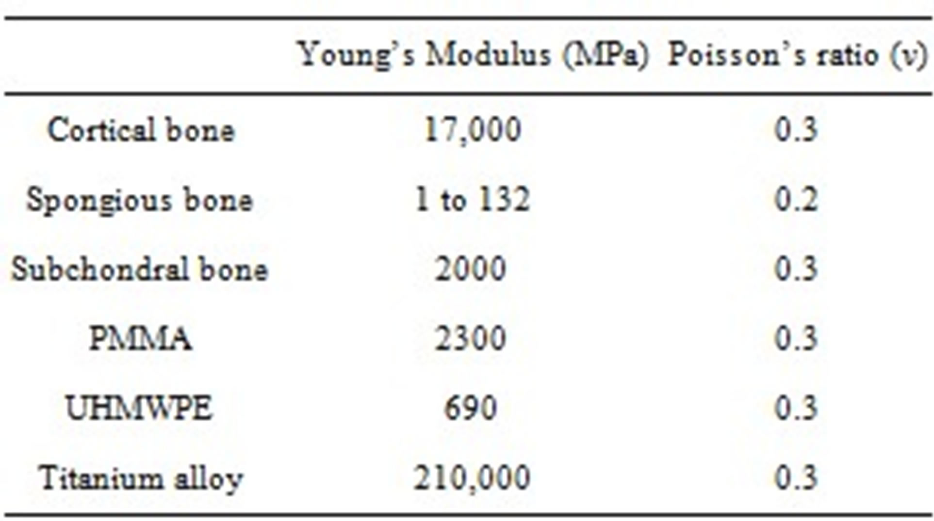
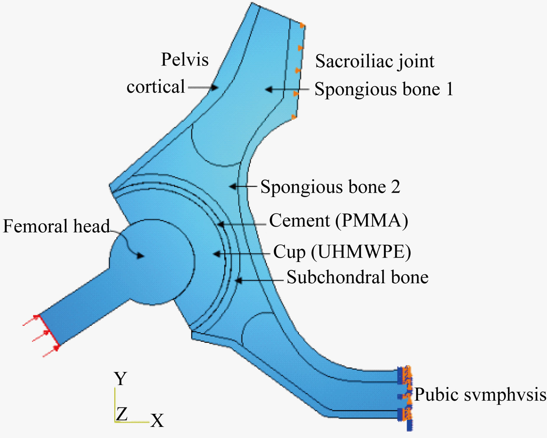
Figure 1. Schematic of reconstructed acetabulum.
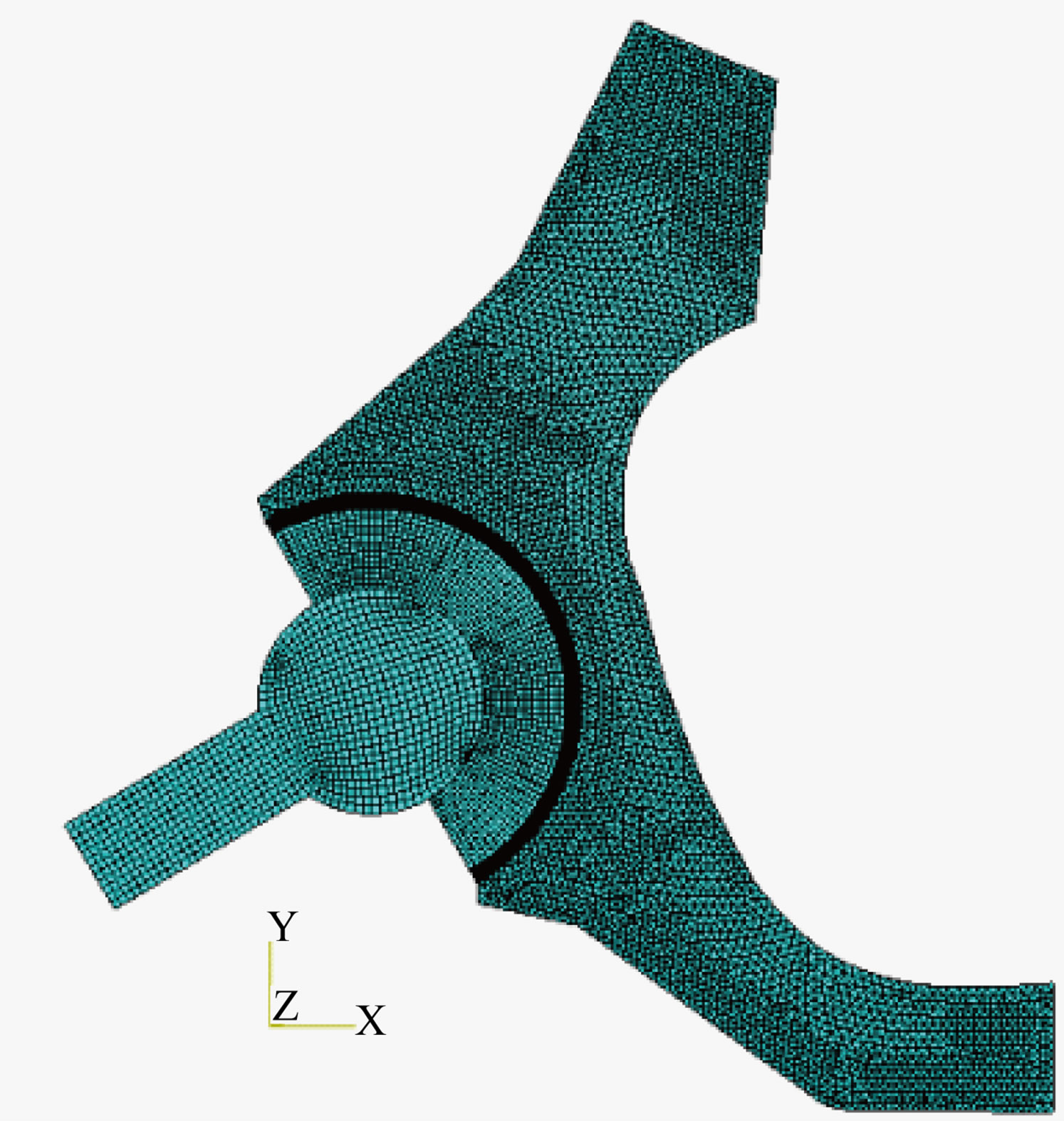
Figure 2. Mesh of the analyzed prosthesis.
cup of 0˚, 25˚ and 50˚ whom reflect the positions of the human body (Figure 3).
3. Results
In all of this study, we analyse the distribution of Von Mises stress in cement for three types of loading, characterized by the neck femoral position compared to the cup axis.
Results represented on the Figures 3 and 4 showed that the distribution of the equivalent stresses in the cement, depending on the nature of loading, is not homogeneous. There exist strongly zones whose intensity depends on the nature loading. Indeed, the orientation of 50˚ of the implant axis compared to that of the cup generates the strongest stress.
3.1. Effect of the Cavity’s Size (Diameter)
The above analysis was made on compact and dense cement in the absence of any porosity. Such a material presents a risk of infection for the subject. To minimize this risk, cement must contain porosities. Our objective is to analyze the effect of this porosity on the stress level and distribution in cement. With this intention, we considered the presence of a cavity (R = 50 μm) in the part of the cement being under very strong stress.
Zones of cement are mechanically differently requested. The stress distribution around the cavity is illustrated on Figure 5. These last shows clearly stress intensification around this defect whose level grows with the implant orientation axis compared to that of the cup.
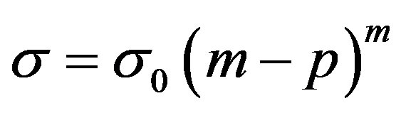
The voluminous fraction of the pores characterized by their size variation plays a determining role in the mechanical behavior of the cement. The coalescence of these pores gives birth to cavities. Our objective is to analyse the density effect of these defects on the stress level and distribution in this structure component. Let us recall that the rupture stress of a solid is closely related to the density of porosity according to the relation (1) [8]:
 (1)
(1)
where:  (dense solid stress);
  (density of porosity);
  (constant) and
  (porous solid stress).
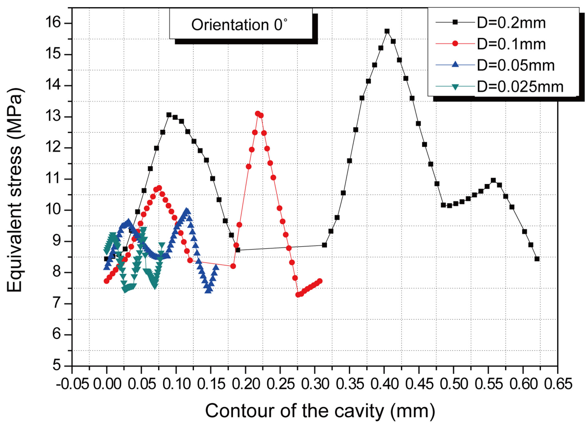
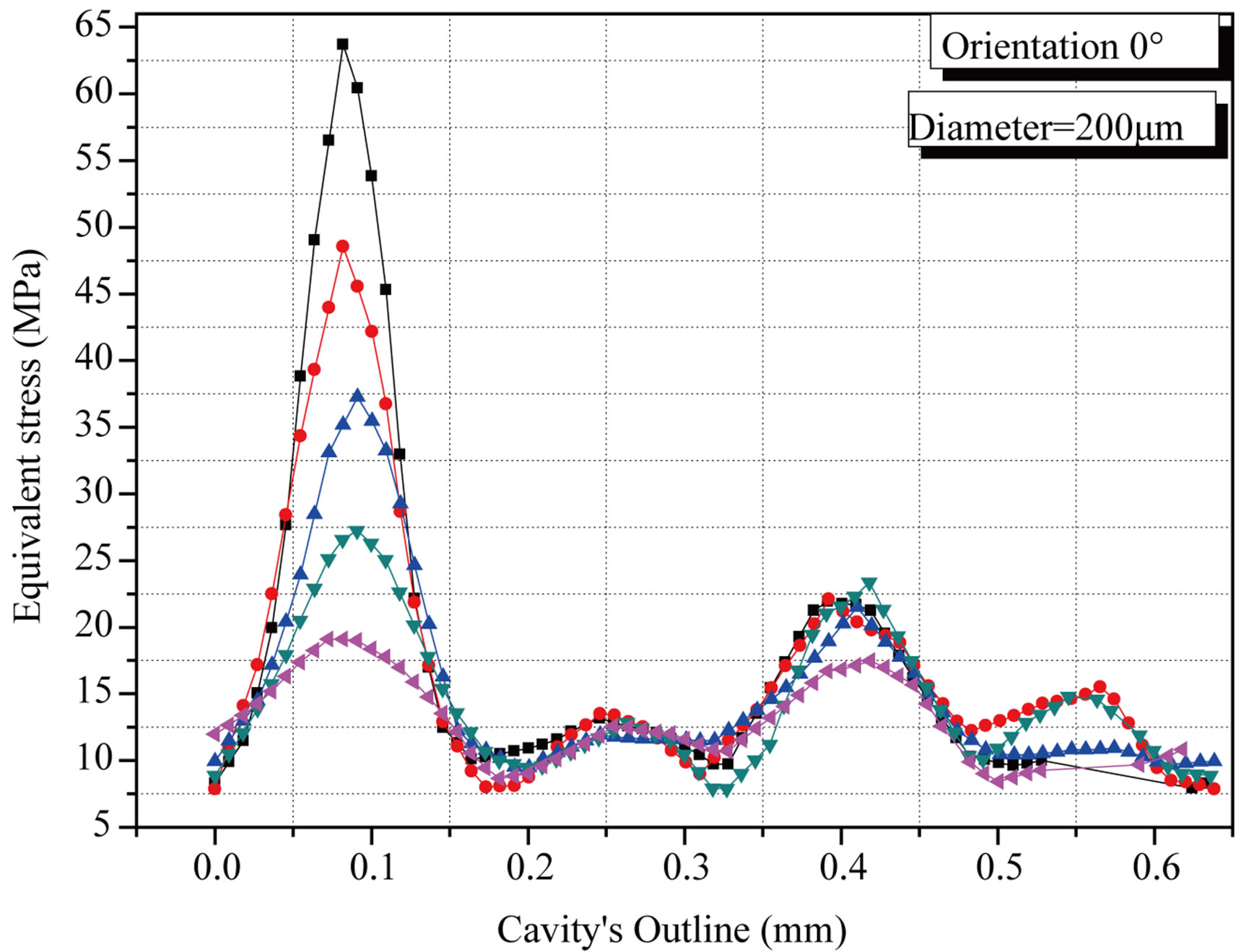
This parameter determines the orthopedic cement durability. Its effect on the stress magnitude and distribution is illustrated in Figure 6. These figures show the stress variation around the defect according to its size and nature loading. The defects with important sizes generate the stronger stress. In other words, a cavity concentrates stress more than one pore. This shows clearly that the phenomenon of pores coalescence presents a risk of intensification stresses in the cement. This risk is more important as the implant axis orientation compared to that of the cup.
Figure 7 shows the variation of the equivalent stress generated in the cement around a large cavity in function of the implant orientation relative to that the cup. This stress increases gradually as the orientation increases and is highly localized in the contact zone cement/cup corresponds to a distance equal to 0.4 mm. This size, creating
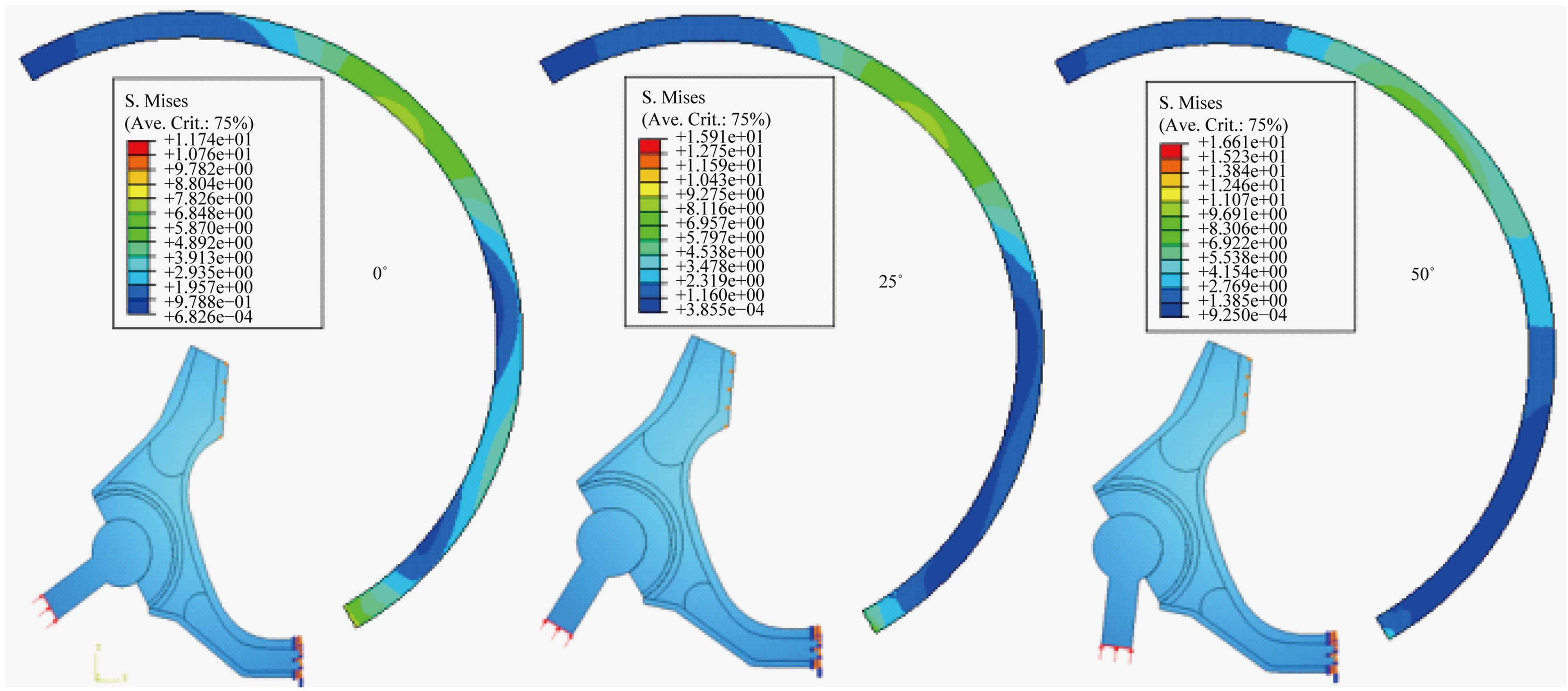
Figure 3. Distribution of the stress in the cement according to the femoral head orientation compared to the cup position axis.

Figure 4. Variation of the stress in the cement according to the femoral head orientation compared to the cup position axis.
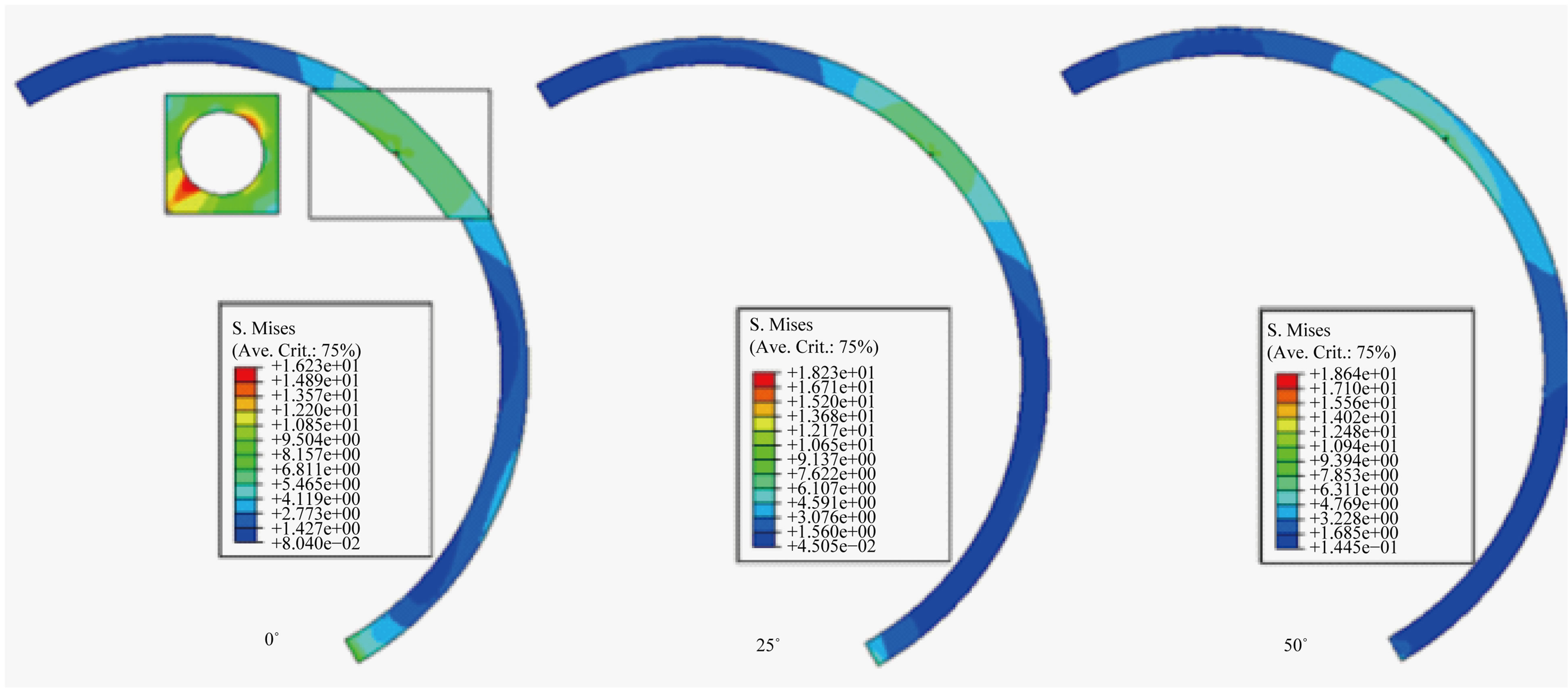
Figure 5. Influence of the nature loading on the stress distribution around the cavity according to the femoral head orientation compared to the cup axis.
 (a)
(a)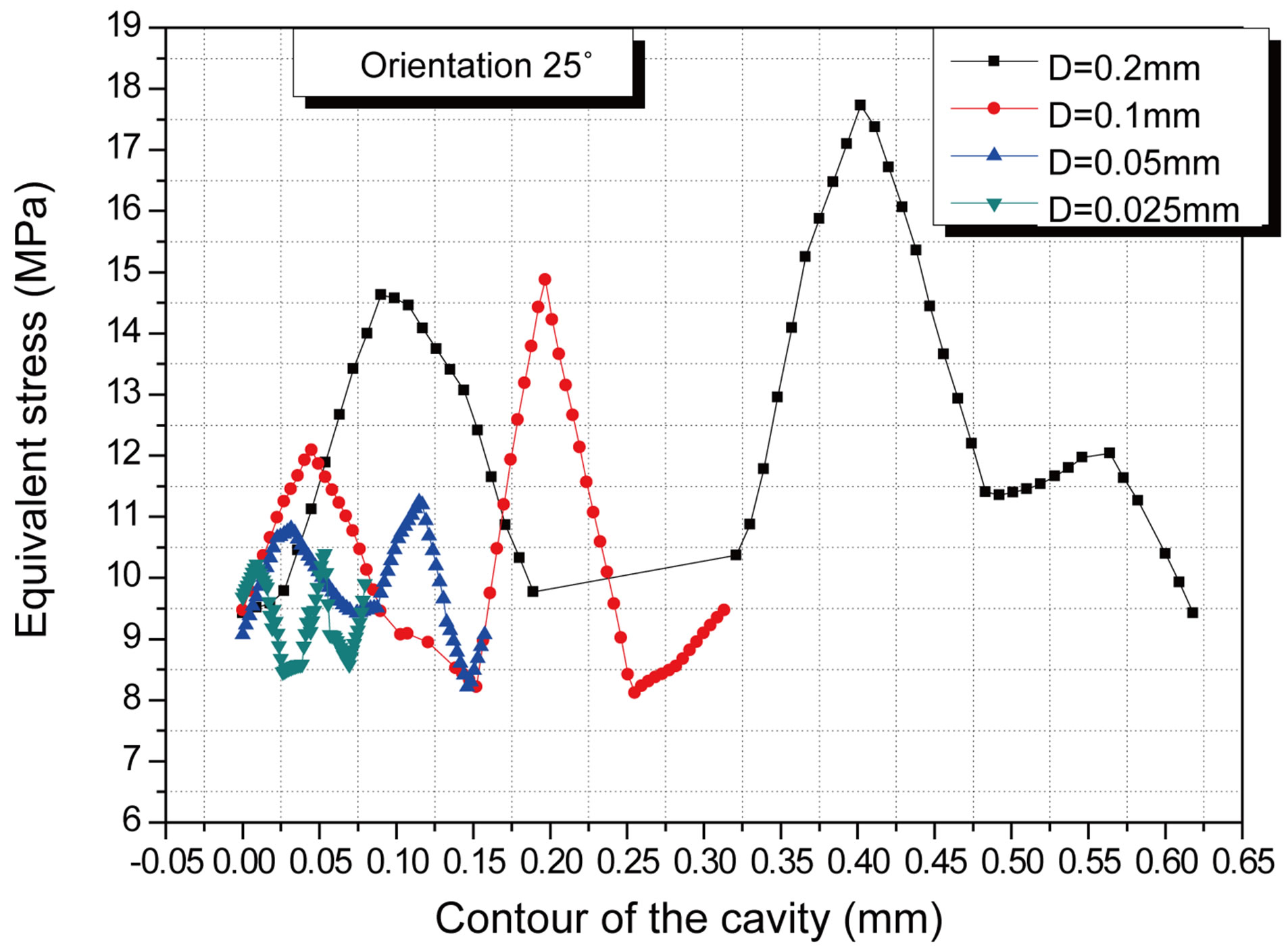 (b)
(b) (c)
(c)
Figure 6. Variation of the stress in the cement around the cavity according to its size and the femoral head orientation. (a) 0˚; (b) 25˚; (c) 50˚.
the most significant stresses in cement, was selected for further analysis.
3.2. Effect of the Cavity-Cavity’s Interaction
The preceding analysis showed that the existence of mi-
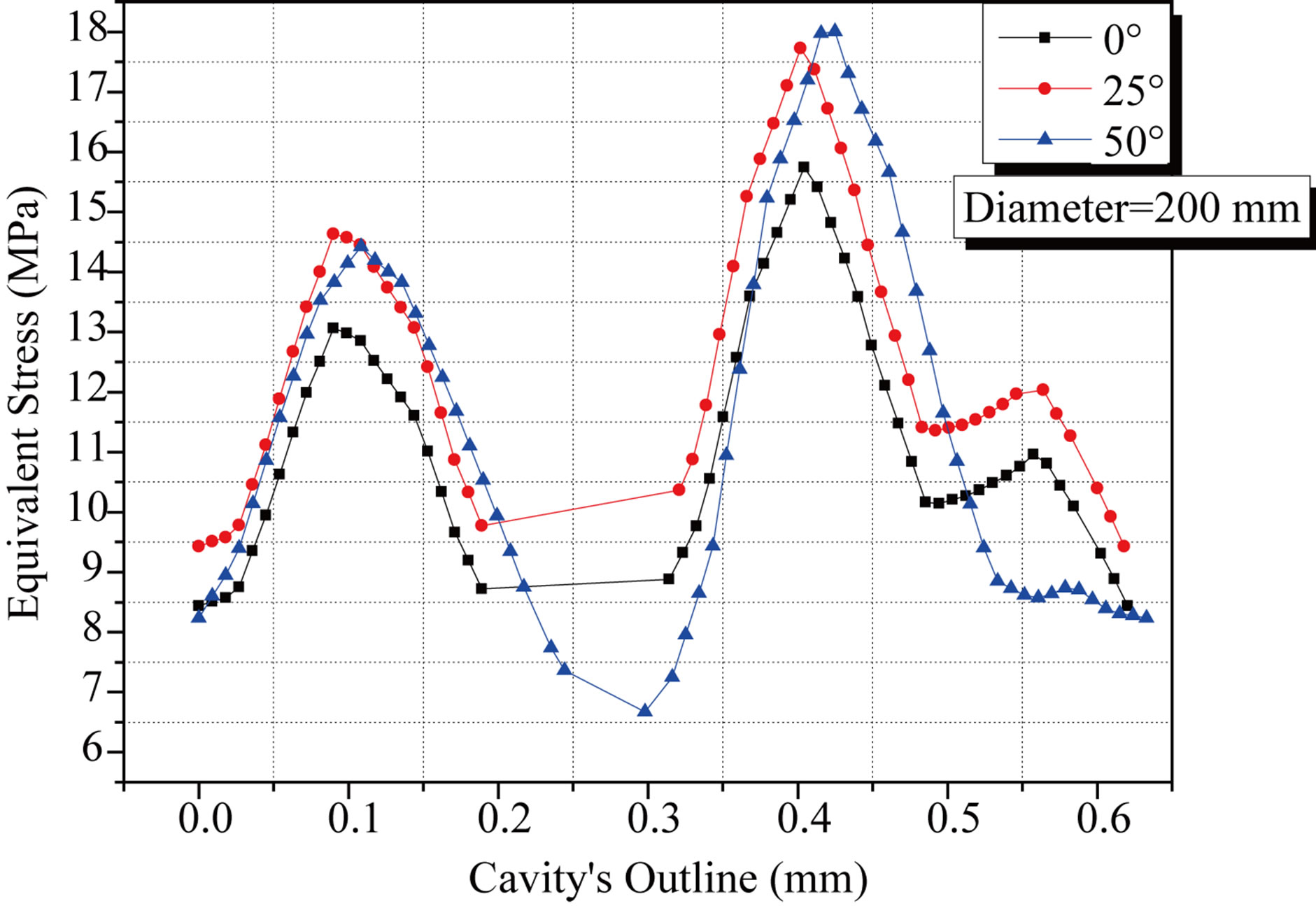
Figure 7. Variations of the stress in the cement around the cavity depending on the nature of the load.
crocavities in cement is the seat of stress concentration. The study on the effect of cavity-cavity interaction is of great importance for the survival of a THP cemented.
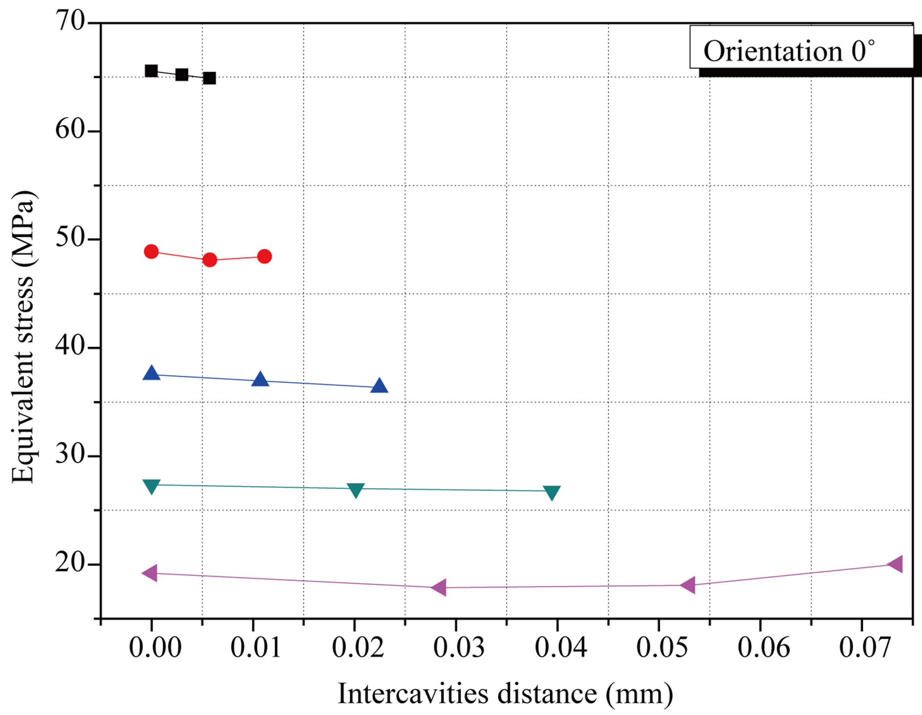
We considered the presence of two cavities (R = 50 μm) in the cement part of the most strongly requested according to the femoral head orientation compared to the cup axis (Figure 8). Results show that the stress in cement between two cavities increases with the decrease of cavity-cavity inter-distance (Figure 9(a)). Cement is under strong stress not in the part of contact with the implant but in the zone between two cavities. The stress intensity has increased by about four times. A rapprochement between two cavities induced a stress of strong amplitude.
They largely exceed the stress threshold of tensile rupture (25 MPA) of this component and reach the level of rupture in compression (80 MPA). From such behavior can result the interconnection from the cavities could lead to a great probability of rupture of the cement and thus of the prosthesis. This risk of damage increases with the augmentation of the implant orientation (Figures 9(b) and (c)).
For better illustrating this effect, an analysis of the stress distribution according to the implant axis inclination compared to that of the cup along the distance between two cavities was carried out (Figures 10(a)-(c)). These figures show that this stress is increasing when these cavities approach one of the other.
It reaches its limiting value when these two defects are one in the vicinity very close to the other and when the position of the neck femoral is strongly oriented compared to the axis of the cup.
4. Discussions
Three of porosity’s types can remain in the cement [9, 10]:
• The gas porosity resulting from trapped air during
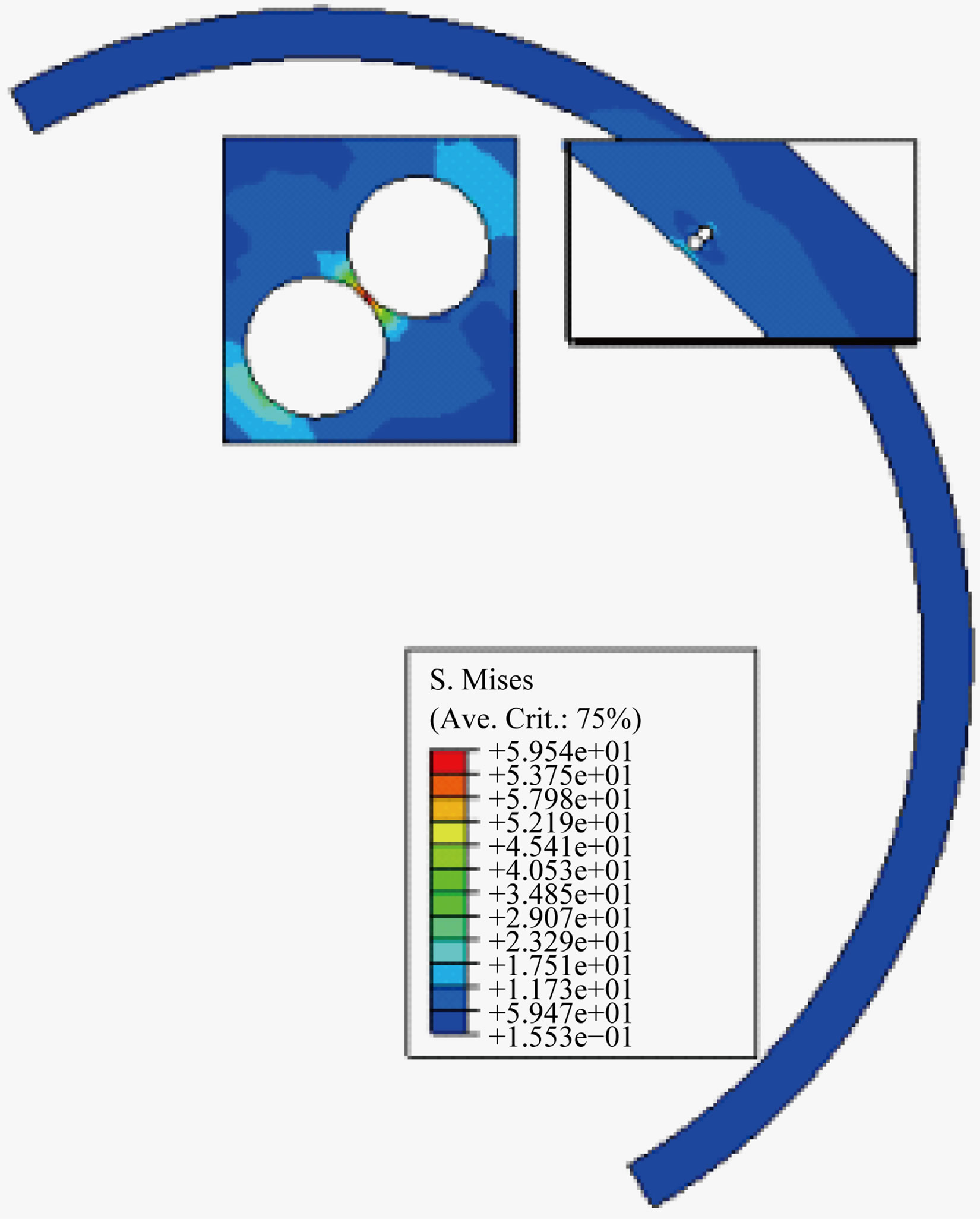
Figure 8. Effect of the cavity-cavity interaction according to the femoral head orientation compared to the cup axis.
mixing of the cement components in the polymerization. These bubbles are always perfectly regular, almost spherical. The diameter of these cavities varies from a few millimeters to micrometers.
• Porosity by vacuum or removal is related to shrinkage during polymerization in vivo. It is the source of inside surface cavities blistered where the emerging spheres making footprints in relief. In a number of cases, these cavities are less regular and can initiate cracks whose starting point is likely to shrinkage;
• Porosity by including blood, bone or soft tissue in the cementing of the implant.
Porosity is an important determinant of mechanical performance of cement. It mainly affects the tensile strength, which is already weak cement, and fatigue, which undermines its long-term effectiveness [11].
Cement is a vector possible pharmacological and porosity is a local broadcast media, including antibiotics and antimitotics. One of its drawbacks is the potential creating irregularities areas of high stress concentrations and thus crack initiation. Coalescence of pores cavities can be fatal for the sustainability of the prosthesis. Indeed, the presence of cavities in the cement weakens by
 (a)
(a)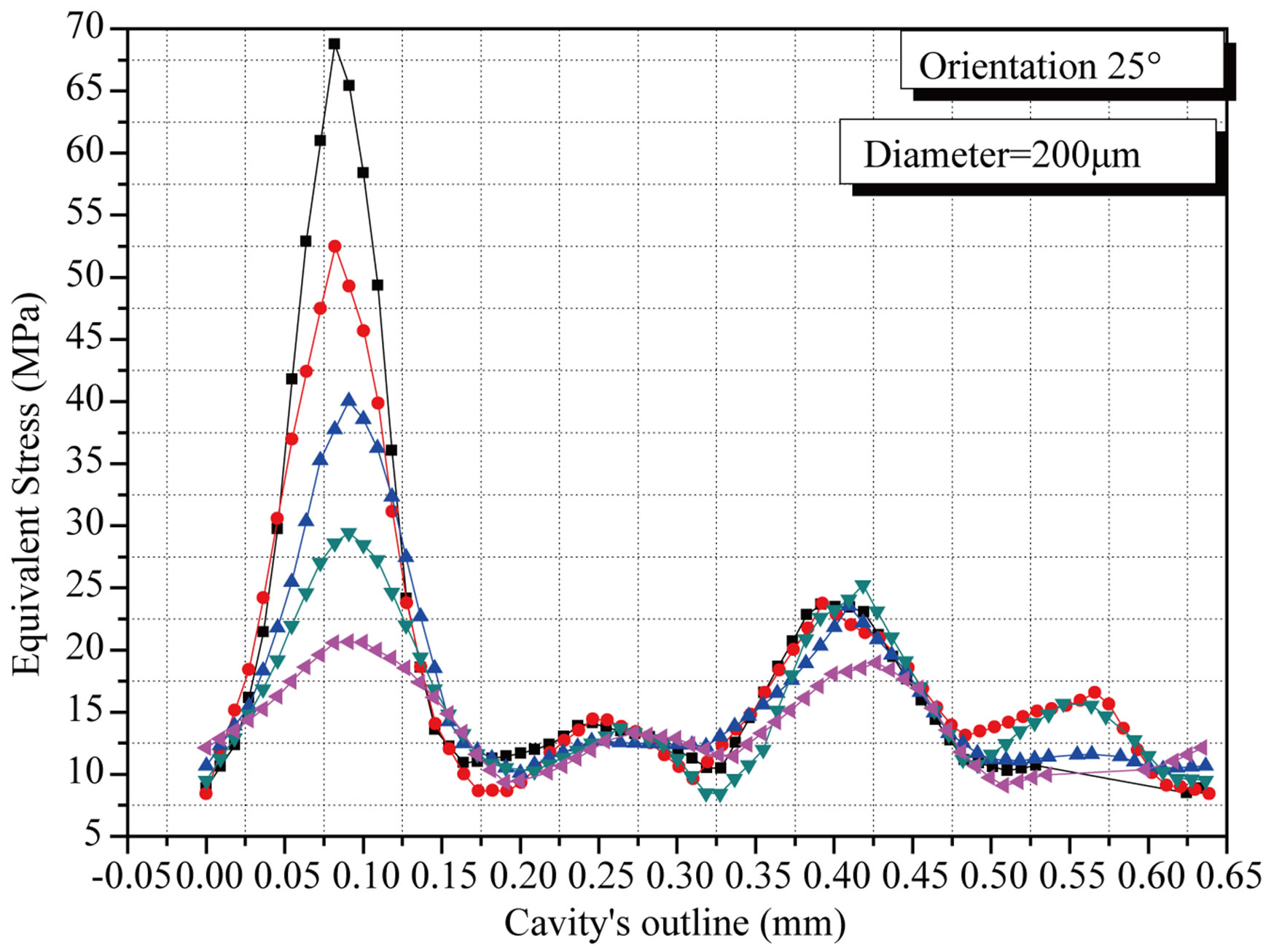 (b)
(b)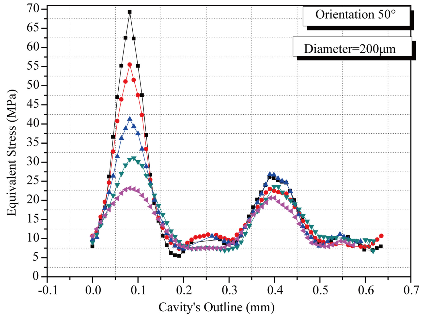 (c)
(c)
Figure 9. Variation of the stress in the cement around the cavity according to the cavity-cavity inter-distance and the femoral head orientation: (a) 0˚; (b) 25˚; (c) 50˚.
 (a)
(a)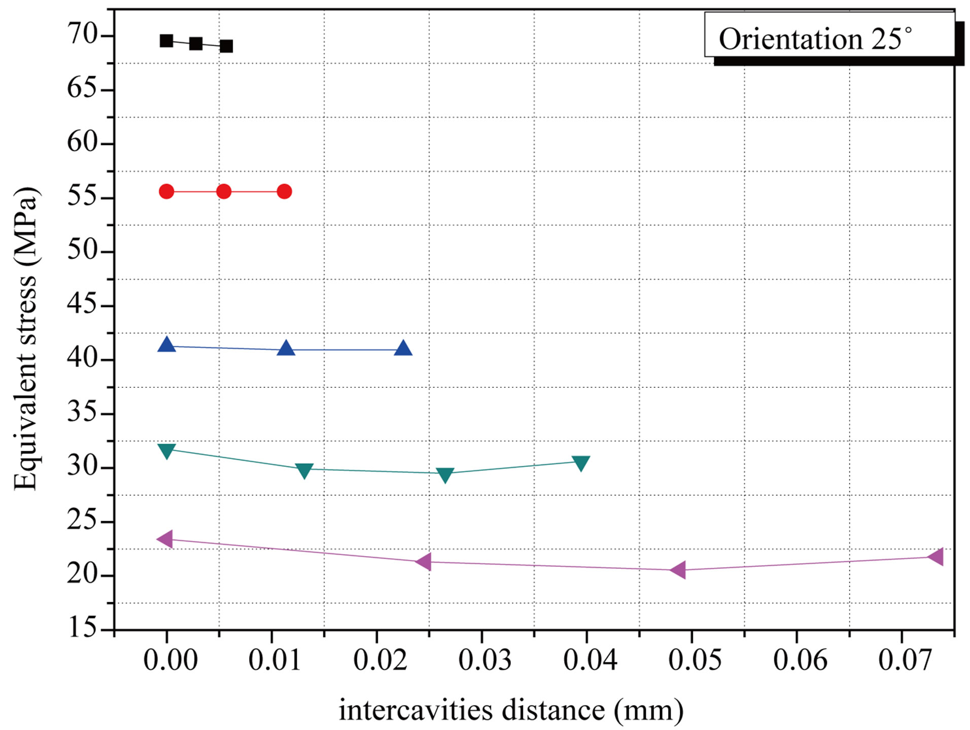 (b)
(b)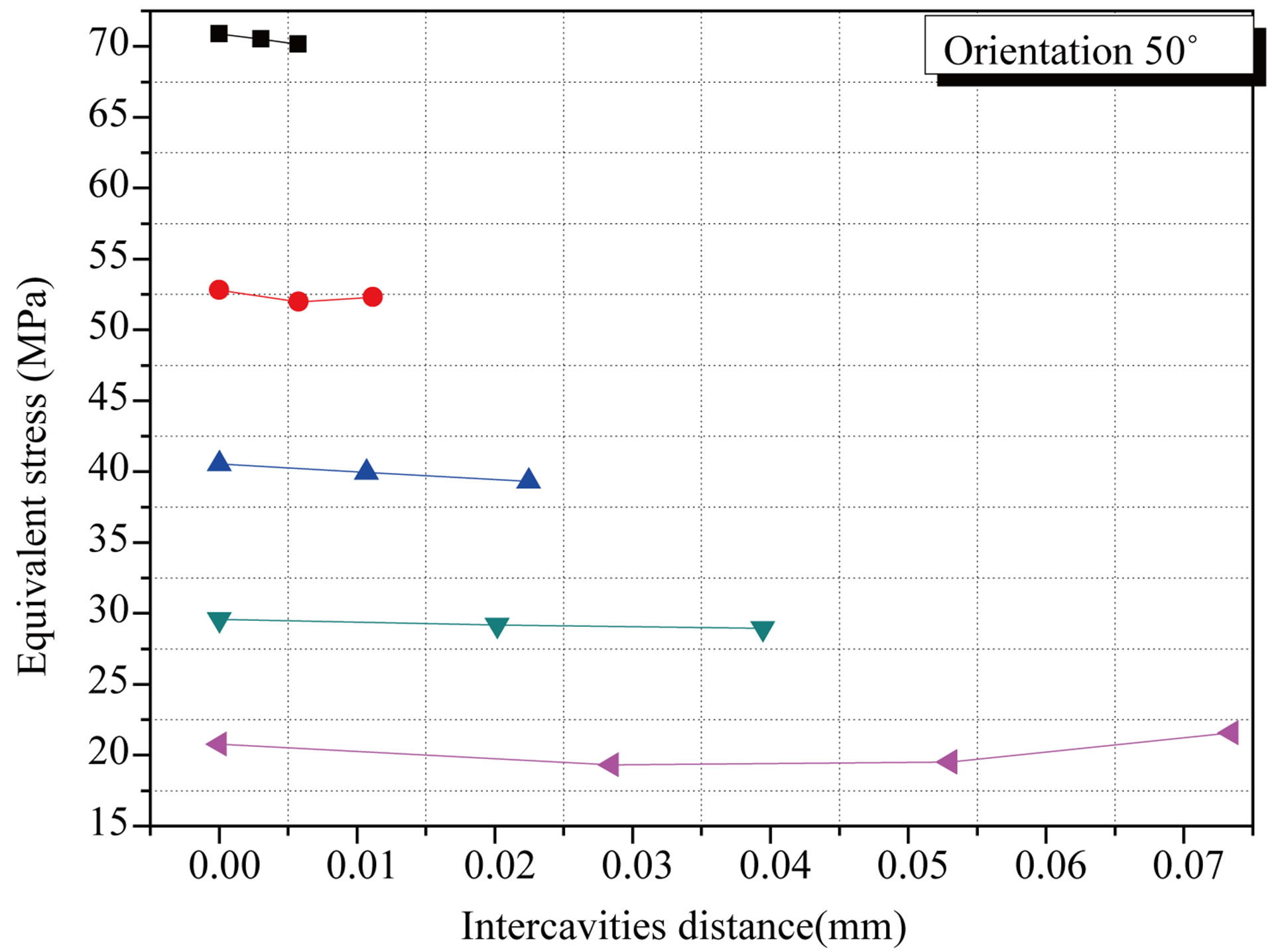 (c)
(c)
Figure 10. Variation of the stress in the cement according to the interdistance cavity-cavity and the femoral head orientation: (a) 0˚; (b) 25˚; (c) 50˚.
notch effect. This risk increases with the size and the volume fraction of the cavities and with the position of the human posture. The cavity-cavity interaction, in this component, generates an equivalent stress of high amplitude. The latter, about three times greater than its tension rupture when these defects are very close in the vicinity of one another, the threshold tends to compression. Such a configuration has a high risk of rupture of the cement and thus a high probability of loosening of the prosthesis. Moreover, coalescence of the cavities, characterized by a large size, can lead to the same effect. The existence of porosities in the bone cement weakens considerably. The life of the prosthesis is closely related to the porosities concentration in the binder.
To fully ensure his function, the cement must ensure both a good transfer of antibiotic load and good adhesion between the elements of the structure, density, porosity must be optimized. This interaction effect tends to disappear when the two cavities are far from each other. They behave as if they are isolated from one another.
4. Conclusions
In this study, a finite element model is developed to calculate Von Mises stress under applied load to the femoral head. The effect of the femoral head orientation compared to the cup Position axis and the existence of the pore in the cement on Von Mises stress.
The following general result may be drawn as a conclusion of this study:
• The distribution of the Von mises stress in cement is not homogeneous. The zone of contact implant-cup is the place of strong stress its intensity depends on the implant position compared to the cup axis;
• The presence of cavities in cement is the seat of stress concentration by notch effect. The stress is strongly localized around this defect. It is not uniformly distributed around the cavity. Its level is closely dependant in keeping with defect and with the nature loading;
• The presence of cavities in the cement weakens it by notch effect. This risk increases with the size and voluminous fraction of cavities as well as with the position of human posture;
• The level of the stress depends on the cavity-cavity interdistance. A short distance generates an intensity of stress three stronger than its stress rupture in tension. The stress rupture in compression is reached. The cement is strongly weakened. The effect of interaction cavity-cavity is marked less when these two defects are far one from the other.
REFERENCES
- S. Benbarek, B. B. Bouiadjra, T. Achour, M. Belhouari and B. Serier, “Finite Element Analysis of the Behaviour of Crack Emanating from Microvoid in Cement of Reconstructed Ace-Tabulum,” Materials Science and Engineering A, Vol. 457, No. 1-2, 2007, pp. 385-391.
- B. B. Bachir, A. Belarbi, S. Benbarek, T. Achour and B. Serier, “FE Analysis of the Behaviour of Microcracks in the Cement Mantle of Reconstructed Acétabulum in the Total Hip Prosthesis,” Computational Materials Science, Vol. 40, No. 4, 2007, pp. 485-491. doi:10.1016/j.commatsci.2007.02.006
- M. M. Bouziane, B. B. Bouiadjra, S. Benbarek, M. S. H. Tabeti and T. Achour, “Finite Element Analysis of the Behaviour of Microvoids in the Cement Mantle of Cemented Hip Stem: Static and Dynamic Analysis,” Materials and Design, Vol. 31, No. 1, 2010, pp. 545-550. doi:10.1016/j.matdes.2009.07.016
- T. Achour, M. S. H. Tabeti, M. M. Bouziane, S. Benbarek, B. B. Bouiadjra and A. Mankour, “Finite Element Analysis of Interfacial Crack Behaviour in Cemented Total Hip Arthroplasty,” Computational Materials Science, Vol. 47, No. 3, 2010, pp. 672-677. doi:10.1016/j.commatsci.2009.10.007
- B. Serier, B. B. Bouiadjra, S. Benbarek and T. Achour, “Analysis of the Effect of the Forces during Gait on the Fracture Behaviour in Cement of Reconstructed Acetabulum,” Journal of Computational Materials Science, Vol. 46, No. 2, 2009, pp. 267-274.
- G. Bergmann, G. Deuretzbacher, M. Heller, F. Graichen, A. Rohlmann, J. Strauss and G. N. Duda, “Hip Contact Forces and Gait Patterns from Routine Activities,” Journal of Biomechanics, Vol. 34, No. 7, 2001, pp. 859-871. doi:10.1016/S0021-9290(01)00040-9
- ABAQUS, Inc., “Abaqus Ver 6-5, User Guide,” Cornell University, Ithaca, 2004.
- B. Serier, “Study and Characterization of Metal-Ceramic Links Developed by Thermo-Compression, Ag/Al2O3 Couple Application,” Ph.D. Thesis, Central School of Lyon, Lyon, 1991.
- S. K. Bhambri and L. N. Gilbertson, “Micro Mechanisms of Fatigue Crack Initiation and Propagation in Bone Cements,” Journal of Biomedical Materials Research, Vol. 29, No. 2, 1995, pp. 233-237. doi:10.1002/jbm.820290214
- P. Pernod. and P. Hernigou, “Morphological Aspect of the Porosity of the Cement,” Romillat Edition, Paris, 1996, pp. 235-240.
- D. Merckx, “Cements in Orthopedic Joint Prostheses Design,” Biomechanics and Biomaterials, Journal of Teaching of the SOFCOT, Vol. 44, 1993, pp. 67-76.
NOTES
*Corresponding author.