Open Journal of Modelling and Simulation
Vol.2 No.2(2014), Article ID:44718,10 pages DOI:10.4236/ojmsi.2014.22009
Implementation of Mooring Automatic Positioning System for Deepwater Semi-Submersible Platform Based on Dual-Stage Actuator
Tao Sun, Wenbin Gui, Zhigang Yu, Zhimin Gao
No.704 Research Institute, CSIC, Shanghai, China
Email: qh0403@qq.com
Copyright © 2014 by authors and Scientific Research Publishing Inc.
This work is licensed under the Creative Commons Attribution International License (CC BY).
http://creativecommons.org/licenses/by/4.0/


Received 10 February 2014; revised 12 March 2014; accepted 20 March 2014
ABSTRACT
The automatic positioning control of mooring system for deepwater semi-submersible platform has become a key issue in the research and development field of deep-sea resources. The DualStage Actuator (DSA) proposed in this paper can replace the single actuator to achieve the high speed and high precision positioning by cooperative control. The relative model and control algorithm of motion trajectory (CAMT) are designed and validated, which proves that the method proposed in this paper is effective.
Keywords:Deepwater Semi-Submersible Platform; Mooring Automatic Positioning; Dual-Stage Actuator (DSA); High Speed and High Precision; the Control Algorithm of Motion Trajectory (CAMT)

1. Introduction
With the development of deep-sea resources which has become the focus of research [1] , the automatic positioning control of mooring system for deep water semi-submersible platform is raised as an important issue, in which the big time delay, multi coupling, large vibration control problem are involved. The control strategy and high speed and high precision implementation of automatic positioning control mooring system are researched in this paper from the aspect of driving structure optimization control.
2. The Sketch of the Mooring Automatic Positioning Algorithm for the Deepwater Semi-Submersible Platform
By coordinating windlass and analog windlass simultaneously, automatic positioning control mooring system can control the movement of deepwater semi-submersible platform.
The research object in this paper is the platform with four symmetric windlasses (12 anchor chains) to remain the platform stable as Figure 1. With the changes of the platform displacement, the angle of anchor chains can be adjusted from 22.5˚ to 67.5˚.
In consideration of the time-lag, coupling and sharp shock of mooring system, the Smith-Fuzzy-PID predictive control strategy is proposed in author’s another paper to get the target trajectory of the platform  and all the set of the displacement control rules
  of for hauling in or paying out each anchor chain under the various external conditions including wind, wave, tide and the others external disturbance. While the platform walks along the target trajectory
  after the adjustment period, the precision of automatic positioning of the mooring system can meet the actual demand. Firstly, the typical displacement control rules of anchor chain are collected by intelligent matching plenty of expert experiences, which can be utilized to form the
  to determine the displacement of each anchor chain in various conditions with Smith-PID predictive control strategy according to actual conditions [2] [3] . Furthermore, in combination with the actual situation and automatic positioning demand of the platform, the target trajectory of platform
  can be obtained based on the
  and the Smith-PID predictive control strategy. The sketch of the Smith-Fuzzy-PID predictive control strategy is described as follows in this paper.
The pure lag compensation controller is shown in Figure 2, where,  is equal to
 , and transfer function can be expressed with Equations (1) and (2).
 (1)
(1)
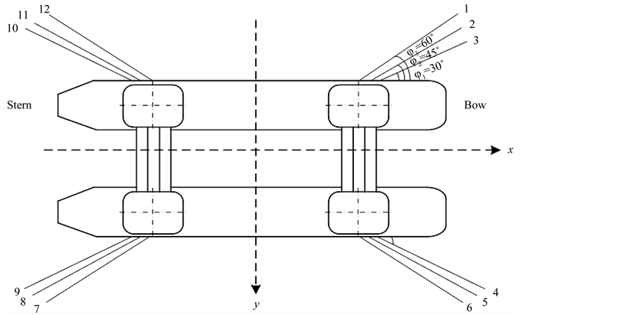
Figure 1. Anchor chain arrangement of deepwater platform.
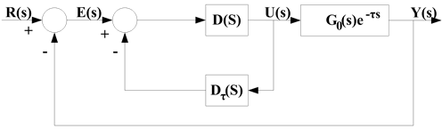
Figure 2. The pure lag compensation controller.
 (2)
(2)
From Equation (2), an equivalent system model can be obtained as Figure 3.
Where, ![]() , by series expansion, transform to the time domain and discretization for
, by series expansion, transform to the time domain and discretization for , the Equation (3) can be obtained.
 (3)
(3)
where, k is sampling instant,  is sampling period, y(k) is the output value on the sampling instant, is the feedback value on the sampling instant, which can obtain the displacement (length) demand of hauling in or paying out each anchor chain under the various external conditions and can be utilized to form all the set of the displacement control rules
 . And a(n) is the equivalent coefficient of y(k–n), which are both constants relevant with time delay
 .
.
The Predictive Control—Equivalent Smith-Fuzzy-PID Algorithm Structure is shown in Figure 4. The predictive weight of feedback channel {a(n)} can be off-line identified by system output values and can be also on-line optimized.
Furthermore, with the Smith-Fuzzy-PID predictive control strategy, the target trajectory of the platform  can be obtained by accurate fitting all the change curves of y(k).
However, with the fuzzy method taken and the existence of the lag factor  during the control rules forming process for anchor chains movement, there should be lager shock in the forward and reverse control process. Thus, the single actuator structure for hauling in or paying out the anchor chain has no enough ability to cooperatively control the high speed and high precision of mooring automatic positioning of deepwater semi-submersible platform, which may cause the potential safety and efficiency hazard.
Based on the preliminary design of the target trajectory of the platform  and all the set of the displacement control rules
  for each anchor chain, the major task in this paper is to replace the single actuator structure with the dual-stage actuator structure to control and promote the speed of mooring automatic positioning and make the platform walk along the expected target trajectory of the platform
  to cooperatively promote the precision of mooring automatic positioning.
3. Principle Analysis of the Dual-Stage Actuator Structure
In the process of movement control of anchor chain, as the actuator of adjusting deviation, the windlass changes the intersection angle of anchor chain and platform by angle displacement of motor to achieve automatic correction.
The dual-stage actuator structure proposed in this paper is clearly distinguishable from any other anchor chain single actuator structure, which replaces the single actuator structure with the dual-stage actuator structure to
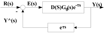
Figure 3. An equivalent system model in smith predictive control strategy.

Figure 4. Predictive control—equivalent Smith-FuzzyPID algorithm structure.
promote the speed and precision of mooring automatic positioning. As shown in Figure 5, the left of the figure provides the movement principle diagram of elbow and wrist, and the right provides the movement principle diagram of dual-stage actuator [DSA] structure for hauling in or paying out anchor chain in the process of mooring automatic positioning, where, O1 is the macro step motor named master actuator with high linear speed, low precision and large travel and O2 is the micro step motor named slave actuator with low linear speed, high precision and short travel [4] -[12] .
4. High Speed and High Precision Dual-Stage Variable Structure Motion Controller
Based on Figure 1 and the preliminary design of the target trajectory of the platform  and all the set of the displacement control rules
  for each anchor chain, the research in this part is divided into two stages, including high speed motion stage and high precision positioning stage.
High speed motion and high precision positioning is the two key issues, meanwhile, which are two conflicting performance requirements. High speed motion should fully take advantage of the driving performance of the windlass to rapidly achieve the maximum speed with maximum acceleration for the anchor chain, and high precision positioning expect that the movement of the platform can accurately fit the expected target trajectory of the platform . Consequently, various controllers should be designed for various motion stages.
In the high speed motion stage, the bang-bang controller is adopted to fully take advantage of the acceleration performance of the windlass. And in the high-speed motion stage, with the help of an iterative learning algorithm (ILC) [13] -[16] which decides the switch position, a bang-bang controller is utilized to make full use of the motor to accelerate or decelerate the windlass, thus eliminates the slowing-down effects of the inertia. Subsequently, a sliding controller is designed to suppress disturbances in the high-precision positioning stage [17] -[20] . Combing these two controllers leads to the iterative learning variable structure controller.
ILC is firstly proposed for reciprocating motion system by M. Uchiyama in 1978. Using this method, the control result in the last sampling period is referenced for adjusting the control variable in current sampling period to achieve the expected performance in this paper.
 has effect on system output after the moment t, thus, the
  can be expressed with ILC approach as follows:
 (4)
(4)
where,  is positive constant,
  represents the system error of tracking the expected motion.
  is the learning pair, the relation can be expressed as Equation (5).
 (5)
(5)
4.1. Controller for High-Speed Motion Stage Bang-Bang Controller
In the high speed motion stage, the bang-bang controller expressed as Equation (6) is adopted to fully take ad-

Figure 5. The motion principle diagram of dual-stage actuator structure.
vantage of the acceleration performance of the windlass. When platform moves (or the length of the anchor chain changes) to a certain point, Motor speed is reduced to 0 with maximum deceleration.
 (6)
(6)
where, p is the switching position. In fact, there are so many uncertain factors that the system model is not accurate enough, and anchor chain can not accurately achieve the expected position when the motor speed is 0. Thus, the actual position of anchor chain  can be optimized by predictive control strategy and ILC to promote the precision of the switch position [21] .
4.2. Controller for High-Precision Motion Stage
Since the sampling period of platform control system is not infinitely small, when the high-speed stage is over, the anchor chain reaches near the expected position calculated with Smith-Fuzzy-PID predictive control strategy ordinarily and there should be deviation between the motion trails of the platform and the expected target trajectory of the platform  calculated with Smith-Fuzzy-PID predictive control strategy. Therefore, a slave actuator is needed to accurately fit the
 . The sliding controller is designed to position the deepwater platform in the high-precision stage with the strong anti-interference ability.
The control equations of anchor chain can be expressed as follows:
 (7)
(7)
 (8)
(8)
where, M is mass matrix, B is bending rigidity of anchor chain,  is effective tension of anchor chain, T is tension of anchor chain, EA is axial rigidity and q is the force on unit length of anchor chain.
The sliding controller in high-precision stage can be expressed as Equation (9).
![]() (9)
(9)
where, ![]() is positive constant,
is positive constant,  ,
,  is the actual switch position. From reference [21] , the controller expressed as Equation (10) can be selected to make the positioning error close to 0.
 (10)
(10)
where,
 (11)
(11)
As a result, the control objective in high-speed stage is to make anchor chain fast reach near the expected position calculated with Smith-Fuzzy-PID predictive control strategy to enter the high-precision stage. And in the high-precision stage, in order to accurately fit the , motion trajectory planning needs to be analyzed and controlled.
5. Implementation of Control Algorithm for High-Precision Stage
As above-mentioned, in the high speed motion stage, the bang-bang controller is adopted to fully take advantage of the acceleration performance of the windlass, and the control objective is already determined by the  and the
  from Smith-Fuzzy-PID predictive control strategy. The major objective in this part is to analyze the control algorithm for motion trajectory fitting the
  of platform in this high-precision stage.
5.1. Predictive Control Mechanism of Rapid Switch Position
In the travel of the slave actuator, the error of tracing accumulated in the high-speed stage should be compensated. As shown in Figure 6, the initial system status is  and
and , position switches at
 . When the system status arrives the new balance point S2,
  , the DSA output can accurately trace the expected
 .
.
5.2. The Control Structure and Algorithm of Motion Trajectory
The motion trajectory command is adjusted with cascade control structure by ILC method to compensate the error of positioning to promote the precision.
5.2.1. Cascade Control Structure of System
Cascade structure is utilized in the controlled, and speed loop is PI control and position loop is P control. The block diagram of the controlled system is shown in Figure 7.
In Figure 7,  is external disturbance,
  is trajectory command,
 ![]() is the output of the displacement of the platform,
is the output of the displacement of the platform,  is the controller parameter of position loop PL,
  is the controller parameter of speed loop VL,
  is the controller parameter of speed loop I, The output model can be expressed as Equation (12).
 (12)
(12)
where,  and
and  are the Laplace transform of
  and
and  in turn. Considering the external disturbance, we can get that
 (13)
(13)
where,
 (14)
(14)
The  in this part, which is the unique expected motion trajectory of platform from Smith-Fuzzy-PID predictive control strategy.
5.2.2. The Control Algorithm of Motion Trajectory (CAMT)
The control algorithm of motion trajectory (CAMT) makes platform trace the expected target trajectory of the platform  by adjusting the trajectory command.
Definition:

Figure 6. Predictive control mechanism of rapid switch position.
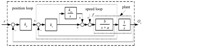
Figure 7. Block diagram of the controlled system.
 is the tracing error at moment t in the ith sampling period, and the trajectory command can be expressed as Equation (15).
 (15)
(15)
where, the ILC of the  is that:
 (16)
(16)
The block diagram of the control algorithm of motion trajectory is shown in Figure 8.
Based on the above DSA, CAMT,  and
and  from Smith-Fuzzy-PID predictive control strategy, the high-speed and high-precision mooring automatic positioning control principle is shown in Figure 9 for the deepwater semi-submersible platform.
6. Simulation Result and Analysis
According to the environmental condition every year, considering the most unfavorable situation with the wind wave and current in the same direction, and taking 600 s as computation time, 14 m is taken as the desired value of platform displacement and the 600 seconds as the desired time to reach the steady state meeting the requirement in the 1500 m water depth and wave direction Angle (135).
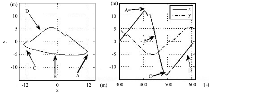
In this condition, based on the Ttplat and Rcdisp from Smith-Fuzzy-PID predictive control strategy, the X-Y displacement expected of platform in the high-precision mooring automatic positioning stage is shown in Figure 10 for the deepwater semi-submersible platform. The A, B, C, D are the points with peak value of speed or acceleration.
In the process of simulation, the control prototype machine for Linear DSA shown in Figure 11 is utilized to verify the Smith-Fuzzy-PID predictive control strategy, the DSA and CAMT proposed in this paper.
The simulation result is shown in Figure 12, it can be seen that the system reaches near the stead state at about 300 s, and in the period from 300 s to 600 s, the platform realizes the process fitting the expected target trajectory of the platform  without large shock and overshoot until 6000 s as shown in Figure 13. Thus, the DSA and CAMT proposed in this paper based on Smith-Fuzzy-PID predictive control strategy are valid to cooperatively
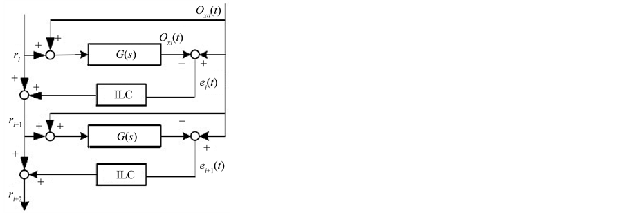
Figure 8. Block diagram of the control algorithm of motion trajectory.
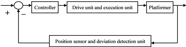
Figure 9. The high-speed and high-precision mooring automatic positioning control principle for the deepwater semi-submersible platform.
 (a) (b)
Figure 10. Displacement expected of platform in the high-precision mooring automatic positioning stage in the X-Y Plane. (a) Expected target trajectory of platform in X-Y plane; (b) Expected displacement of platform in the direction of X-axis and Y-axis.
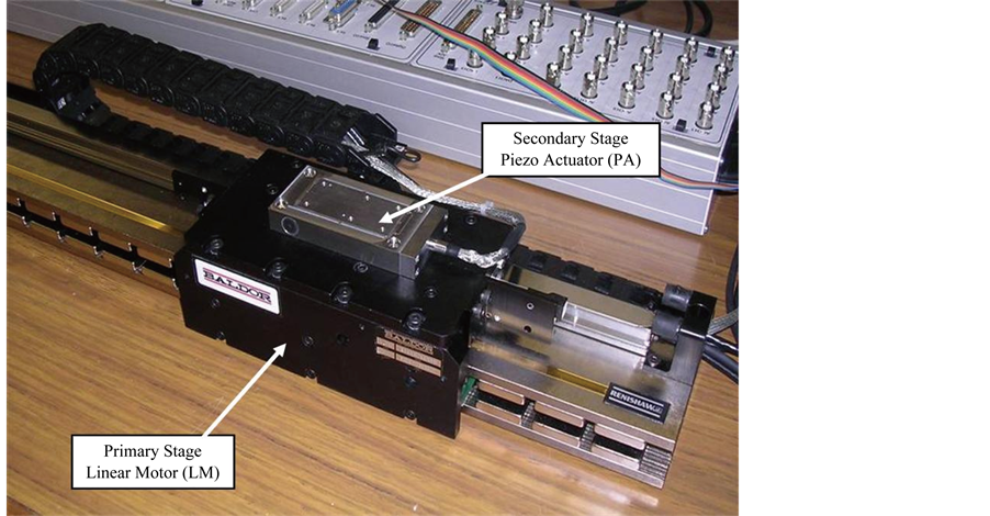
Figure 11. The control prototype machine for linear DSA.
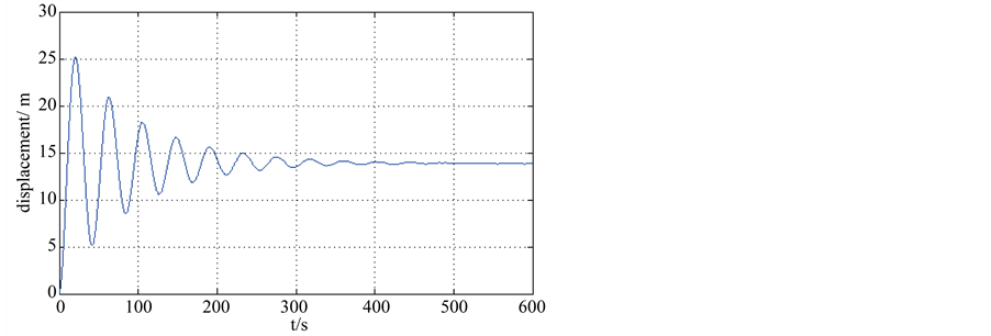
Figure 12. Displacement of platform within 600 s by DSA and CAMT.
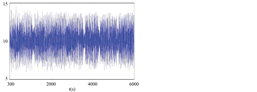
Figure 13. Displacement of platform within 6000 s by DSA and CAMT.
control and promote the speed and precise of mooring automatic positioning for the deepwater semi-submersible platform.
7. Conclusions
The DSA and CAMT proposed in this paper based on Smith-Fuzzy-PID predictive control strategy are used to cooperatively control and promote the speed and precise of mooring automatic positioning for the deepwater semi-submersible platform.
In the high-speed motion stage, a bang-bang controller is utilized to make full use of the motor to accelerate or decelerate the windlass. And a sliding controller is designed to suppress disturbances in the high-precision positioning stage to promote the precision of positioning.
The simulation result proves that the DSA and CAMT proposed in this paper are valid to achieve the high speed and high precision of mooring automatic positioning for the deepwater semi-submersible platform.
However, the high acceleration in the high-speed stage could make the platform vibrate to affect the precision of mooring automatic positioning, which should be discussed in the future research.
Acknowledgements
This research was financially supported by the Marine engineering equipment scientific research project of National ministry of industry and information technology of China (Department of Industry and Information Technology Equipment [2009]91).
References
- Sun, T., Gui, W.B. and Yu, Z.G. (2012) Semi-Submersible Platform Positioning Mooring Control Test System Design and Application. Marine Engineering, 2, 84-86.
- Rad, A.B., Lo, W.L. and Tsang, K.M. (2003) Simultaneous Online Identification of Rational Dynamics and Time Delay: A Correlation-Based Approach. IEEE Transactions on Control Systems Technology, 11, 957-959. http://dx.doi.org/10.1109/TCST.2003.819594
- Ibrahim, K. (2001) Improving Performance Using Cascade Control and a Smith Preditor. ISA Transactions, 40, 223- 234. http://dx.doi.org/10.1016/S0019-0578(00)00054-9
- Elfizy, A., Bone, G. and Elbestawi, M. (2005) Design and Control of a Dual Stage Feed Drive. International Journal of Machine Tools and Manufacture, 45, 153-165. http://dx.doi.org/10.1016/j.ijmachtools.2004.07.008
- Fung, R., Hsu, Y. and Huang, M. (2009) System Identification of a Dual-Stage XY Precision Positioning Table. Precision Engineering, 33, 71-80. http://dx.doi.org/10.1016/j.precisioneng.2008.04.002
- Mori, K., Munemoto, T., Otsuki, H., Yamaguchi, Y. and Akagi, K. (1991) A Dual-Stage Magnetic Disk Drive Actuator Using a Piezoelectric Device for a High Track Density. IEEE Transactions on Magnetics, 27, 5298-5300.
- Jing, Y., Luo, J., Yi, X. and Gu, X. (2004) Design and Evaluation of PZT Thin-Film Micro-Actuator for Hard Disk Drives. Sensors and Actuators, 116, 329-335. http://dx.doi.org/10.1016/j.sna.2004.05.006
- Kobayashi, M. and Horowitz, R. (2001) Track Seeking Control for Hard Disk Dual-Stage Servo Systems. IEEE Transactions on Magnetics, 37, 949-954. http://dx.doi.org/10.1109/20.917648
- Lee, S. and Kim, Y. (2004) Minimum Destructive Interference Design of Dual Stage Control Systems for Hard Disk Drives. IEEE Transactions Control Systems Technology, 12, 517-531. http://dx.doi.org/10.1109/TCST.2004.825049
- Hredzak, B., Herrmann, G. and Guo, G. (2006) A Proximate-Time-Optimal Control Design and Its Application to a Hard Disk Drive Dual-Stage Actuator System. IEEE Transactions on Magnetics, 42, 1708-1715. http://dx.doi.org/10.1109/TMAG.2006.872003
- Iamratanakul, D. and Devasia, S. (2009) Minimum-Time/Energy, Output Transitions for Dual-Stage Systems. Journal of Dynamic Systems, Measurement, and Control, 131. http://dx.doi.org/10.1115/1.3072153
- Huang, X. and Horowitz, R. (2005) Robust Controller Design of a Dual-Stage Disk Drive Servo System with an Instrumented Suspension. IEEE Transactions on Magnetics, 41, 2406-2413. http://dx.doi.org/10.1109/TMAG.2005.852179
- Kuc, T.Y., Lee, J.S. and Nam, K. (1992) An Iterative Learning Control Theory for a Class of Nonlinear Dynamic Systems. Automatica, 28, 1215-1221. http://dx.doi.org/10.1016/0005-1098(92)90063-L
- Saab, S.S. (1994) On the P-Type Learning Control. IEEE Transactions On Automatic Control, 39, 2298-2302.
- Chien, C.J. and Liu, J.S. (1996) A P-Type Iterative Learning Controller for Robust Output Tracking of Non-Linear Time-Varying Systems. International Journal of Control, 64, 319-334. http://dx.doi.org/10.1080/00207179608921630
- Arimoto, S. (1990) Learning Control Theory for Robotic Motion. International Journal of Adaptive Control and Signal Processing, 4, 543-564. http://dx.doi.org/10.1002/acs.4480040610
- Wang, Y. and Han, D. (2007) Fast Response and Robust Controller Based on Continuous Poles Configuration and Time Delay Control. Robotics and Computer Integrated Manufacturing, 23, 152-157. http://dx.doi.org/10.1016/j.rcim.2005.12.005
- Slotime, J. and Li, W.P. (1991) Applied Nonlinear Control. Prentice Hall.
- Xiao, Y.L. and Sarah, K.S. (1997) Robust Sliding Mode Control of Uncertain Nonlinear Systems. Systems & Control Letters, 32, 75-90. http://dx.doi.org/10.1016/S0167-6911(97)00061-3
- Young, K.D., Utkin, V.I. and Ozguner, U. (1999) A Control Engineer’s Guide to Sliding Mode Control. IEEE/ASME Transactions on Control Systems Technology, 7, 328-342. http://dx.doi.org/10.1109/87.761053
- Wu, J.H. (2009) Fast High-position Control of Servo System Driven By Linear Motors with High Acceleration, Shanghai Jiao Tong University Library, Shanghai, 53-80.