Open Journal of Energy Efficiency
Vol.2 No.1(2013), Article ID:29009,5 pages DOI:10.4236/ojee.2013.21005
Test Apparatus for Performance Evaluation of Compressed Air End-Use Applications
1A.T.E. Enterprises Private Limited, 2 Shreenivas Classic, Pune, India
2Birla Accucast Limited, MIDC Waluj Industrial Area, Aurangabad, India
Email: vishalsir@gmail.com
Received January 17, 2013; revised February 18, 2013; accepted March 8, 2013
Keywords: Compressed Air; Utilization Side; Test Apparatus; Performance Estimation; Pneumatic Equipment; Pneumatic Blow Gun
ABSTRACT
Compressed air is an integral utility part of industrial utility systems. Any improvement in compressed air system will lead to reduction in utility cost. The effectiveness of utilization side of compressed air is usually dependent upon operator’s discretion. There is no performance testing methods available for testing existing end use equipments. A test apparatus for estimation of compressed air flow based on measurement of pressure reduction in a fixed volume cylinder in a given time is developed. The test apparatus is easy to build and simple to operate in an industrial environment. This can be used for measuring performance of any pneumatic end-use equipment and for benchmarking the performance. The test apparatus was used in a foundry for quantifying the performance of the old and new blow guns.
1. Introduction
Compressed air is a key utility after electricity, gas and water, and contributes to a major factor of utility cost in manufacturing plants. In compressed air systems the efficiency of conversion from electrical input-to-kinetic energy output at usage point is around 10 percent Ming [1]. It is generated centrally using compressors and then distributed for utilization in the manufacturing plant. The flow and pressure of compressed air determine the power requirement of the compressor, typically 1 kW of electricity can produce 10 m3/hr (6 cfm) compressed air at 7 bar (g) pressure [2]. Compressed air is used in every sector of industry in the areas of process control, actuators, material conveying, blowing and moulding etc. For any compressed air application, the amount of air used should be at the minimum pressure required for the operation and used for the shortest possible duration. Compressed air usage should be constantly monitored and re-evaluated [3].
In a best practice program for compressed air James and Peter [4] suggested the target towards the efficient operation of compressor is achieved by minimizing leakages, avoiding wastages and misuse. More and more efficient compressors are being introduced to reduce the specific energy consumption (SEC) measured in terms kWh/m3. Efficient use of compressed air system on utilization side is possible only by user’s initiative. Antonio et al. [5] has discussed utilization side performance improvement solutions like end-use pressure reduction, volumetric flow control, demand flow control and alternative solution for compressed air usage. However, the performance of end-use equipment is not tracked in terms of flow measurement in industries as an operational practice.
Compressed air on utilization side is used for powering pneumatic tools, operation of air-actuated equipment, dust filtration shake down, blow guns and other similar applications. The manufacturers of compressed air enduse equipment generally specify the compressed air consumption at different air pressures. Amount of compressed air consumed for the end-use operation in an intended task is determined by the operating pressure and time duration of the operation. At end-use points pressure is regulated using local pressure reducing valves for achieving desired action from pneumatic equipments. Any deterioration in the pneumatic equipment performance is usually overcome by increasing the operating pressure (changing pressure reducing valve manually) which leads to higher consumption of compressed air.
The use of efficient end-use equipment on utilization side is a promising area for improving compressed air system performance. The end-use equipment performance can be measured in terms of compressed air consumption at a given pressure. The flow rate of individual end-use equipment is small (about 1% to 5%) as compared to the overall compressed air flow in the system. There are conventional flow meters available for measurement of compressed air flow which are generally used on the main distribution lines. These flow meters are costly and difficult to adopt for measurement of small flow rates encountered for end-use equipment Koski [6].
In a compressed air system the compressor performance is measured with pump up test using existing compressor receivers. Table 1 summarizes compressed air system performance measuring methods. There is a leakage test method for quantification of compressed air leakage in distribution system which is used effectively by industries for monitoring the leakage and initiate leakage sealing drives [2]. There is no simple quantification test method or test apparatus available for quantification of compressed air flow in an end-use equipment.
A simple and cost effective test apparatus is developed for flow measurement of the compressed air end-use equipment. The test apparatus is used in a foundry for measurement of compressed air flow for old and new blow guns and the effectiveness of the test apparatus is demonstrated.
2. Test Apparatus
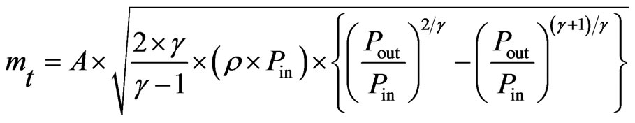
The proposed test apparatus consists of a compressed air storage tank with an inlet, outlet and drain valve. The storage tank is mounted on a movable skid for testing different compressed air usage points. The test apparatus is installed with pressure gauges and a temperature gauge. The drain valve installed is used for removing the moisture from the storage tank. The construction detail of the test apparatus is provided in Figure 1. The reduction of pressure and the operating temperature of compressed air in the storage tank are the main parameters measured during the operation of the test apparatus. The test apparatus is used for estimation of air flow based on reduction of compressed air pressure in the storage tank (of known volume) in a given time. The principle used considers air as an ideal gas with unsteady flow from the storage tank given in Equation (1),
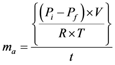 (1)
(1)
where, ma is actual mass flow rate of air in kg/s; Pi is initial pressure in kPa; Pf is final pressure in kPa; t is time in s; R is characteristic gas constant for air in kJ/kg K; T is temperature in K.
The test apparatus is connected to the end-use point through a flexible pipe after a valve V1, shown in Figure 1. The air is supplied to the storage tank from a compressed air header using a valve V2. After the storage tank is filled to the level of the compressed air header pressure monitored with the help of a pressure gauge P1, the valve V2 is closed to isolate the header from the storage tank. The moisture in the storage tank is drained with help of a valve V3. The valve V1 is adjusted to set the required pressure of end-use point with the help of a pressure gauge P2.
The compressed air is used for application after recording of initial pressure of the storage tank using the pressure gauge P1 and a temperature sensor T1. The time taken for pressure reduction in the pressure gauge P1 is monitored with help of a stop watch. The reduction in pressure and time required for the pressure reduction is used for estimation of mass flow rate with the help of Equation (1).
Some of the advantages of the test apparatus are
• Low cost compared to compressed air mass flow meter;
• Easy and accurate measurement of small quantity of flow rates;
• Simple to operate in an industrial environment similar to compressor pump-up test;
• No need of special calibration, standard calibrated pressure and temperature sensors can be used;
• Does not create any pressure drop in the system;
• Limitations of test apparatus developed;
• Cannot be installed for online measurement;
• Size and weight of system is more as compared to mass flow meters;
• Manual intervention required for operation and observations.
The test apparatus developed can be used for the quantification of compressed air flow for an end-use equipment. The quantification of flow can be used as a benchmark of performance and any increase in the compressed air flow compared to benchmark reflects performance deterioration. The quantification of performance deterioration will be helpful for taking corrective actions to restore the performance. The test apparatus can also be used for testing effectiveness of repair and maintenance of the compressed air end-use equipment by measuring per-
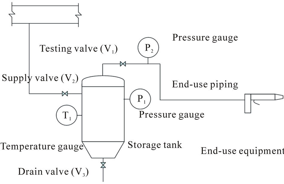
Figure 1. Experimental setup for characterization of blow gun.
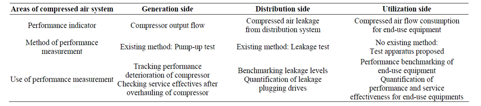
Table 1. Compressed air system performance measuring methods.
formance before and after the maintenance. This can also be used for selecting energy efficient end-use equipment, where the performance of the new and old end-use equipment is compared. This also can be used for validating the efficiency of end-use equipment compared to the supplier’s claims.
3. Performance Measurement of a Blow Gun
Field studies to measure the performance of a blow gun using the test apparatus were carried out in a foundry located in Aurangabad, India. The foundry has three numbers of Atlas Copco make compressors installed in the utility block of the foundry and compressed air is used for various end-use applications. The compressed air system layout along with compressor specifications and end-use applications is presented in Figure 2.
The Shell machine (SM) and Core machine (CM) are moulding machines which pack sand and draw steel pattern to manufacture the sand shell and core (Choudhary and Choudhary [7]). The machines uses resin sand in steel patterns and are heated externally for curing. The compressed air is used mainly for sand shooter, pneumatic cylinders and cleaning of shell and core pattern by direct air blowing.
The foundry had taken up the drive for leakage minimization and eliminating major leakage by conducting periodic leakage test during scheduled maintenance. The next area identified for improvement was use of efficient blow guns for direct blowing applications. The installation of efficient blow guns (air nozzles) would meet the process requirements with significantly reduced compressed air consumption.
Compressed air flow in open end-use applications such as blow-off, part clearing, and moisture removal is auto controlled using a solenoid valve or manually controlled by equipment operators via in-line valves. Blow-off and part positioning on selected equipment is achieved with a steady stream of high velocity compressed air. Open or crimped tubing is often used as a delivery nozzle and pressures are often unregulated.
In the foundry high velocity jets created by blow guns are used for the cleaning of the resin sand burrs generated on the steel pattern during thermosetting of shell and
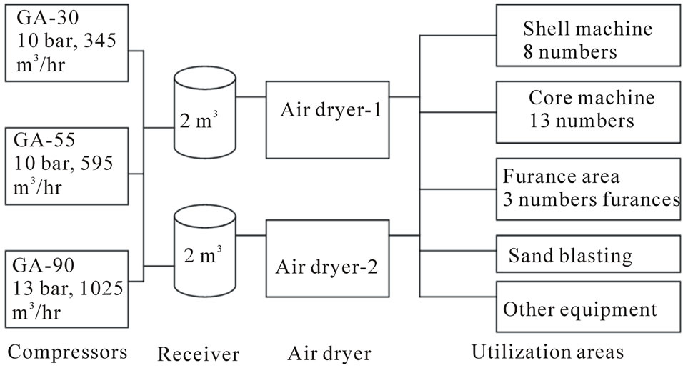
Figure 2. Compressed air system layout at the foundry.
core making operation. Cleaning of the pattern is critical for proper curing of the shell and core. The SM and CM operator does blow gun pressure setting for each blow gun independently. During the SM and CM survey the variation in local pressure setting was observed in the range of 3 - 5 bar (g) at different machines.
More efficient use of compressed air can be achieved by regulating pressures and using flow control devices for delivery such as entraining blow gun with nozzles and air amplifiers. These devices use flow dynamics and geometric design to entrain ambient air into the compressed air stream. By doing so, a greater volume of air is delivered at the point-of-use, thereby limiting the quantity of air that must be supplied directly by the compressed air system.
The foundry was interested for replacing their existing blow guns (old blow guns) with air amplifying blow guns (new blow guns). In order to adopt the new blow guns it was important to measure the air consumption of the old and new blow guns at a given operating pressure. The test apparatus is used for the new and old blow gun to measure the flow output at different operating pressures. The specifications of the test apparatus used in the foundry are provided in Table 2.
No performance curve of air consumption was available for the old blow guns. The new blow gun supplier provided the characteristic curve for mass flow rate at various operating pressures for a particular model of blow gun-“Ex-blow gun”. The data generated from the characterization of the Ex-blow gun with the test apparatus is used for the validation with the manufacturer’s data sheet. Figure 3 presents the comparison of the performance characterization of the Ex-blow gun for measured data and the data supplied by the manufacturer. The experimental measurement follows the manufacturer’s data except for the error band due to the measuring instruments.
Ex-blow gun is used for low penetration and wide flow blow application; it may be difficult to clean stubborn dirt particles in narrow passages and deep grooves. The shell and core cleaning with blow gun falls in this category. In order to cope up with such situation the manu-facturer recommended a high thrust blow (HTB) nozzle mounted on a pistol shape (PSH) blow gun.
The performance characterization for PSH with HTB is not available in the manufacturer’s catalogue. After successful testing of PSH gun on for shell and core blowing, a performance characterization is performed using the test apparatus. Figure 4 indicates the variation of flow output with operating pressure for old gun and PSH gun. The flow delivered by PSH gun is more than old gun at same operating pressure. The difference in the flow delivered by the new and the old gun increases with increase in operating pressure (shown in Figure 4). The old blow gun was operating at 4 bar (g) and delivering about 9.8 m3/hr flow rate, the new blow gun can deliver same flow rate at 2.7 bar (g). The test apparatus was useful for the foundry to quantify the performance of the new and old blow guns before taking replacement decision. The test apparatus can be utilized for other compressed air end-use equipments for performance characterization.
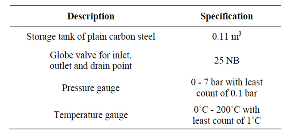
Table 2. Specifications of test apparatus.
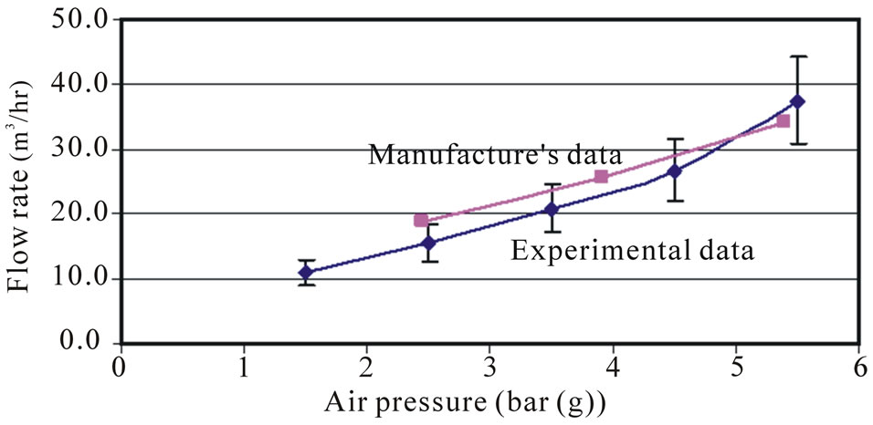
Figure 3. Comparison of experimental and manufacture’s performance for Ex-blow gun [8].
The supply pressure for both blow guns is in the range 2 to 6 bar (g). Due to the operating pressures the pressure ratio is less than 0.528. Hence the compressible flow Eq. 2 is used for estimation of theoretical flow from the blow gun. The ratio of actual measured flow to that of theoretical flow (Equation (3)) provides coefficient of discharge for the old and PHS blow gun.
 (2)
(2)
 (3)
(3)
where, mt is theoretical mass flow rate from blow gun kg/s; Cd is coefficient of discharge for blow gun; A is area of nozzle m2; γ is polytrophic index for air; Pin is upstream pressure Pa; Pout is down stream pressure Pa; ρ is density of air kg/m3.
The result of estimation of coefficient of discharge with experimental uncertainty for the old blow gun was 0.42 ± 0.1 and for the PSH blow gun was 0.75 ± 0.12. The test apparatus can also be used for the estimation of compressed air flow for a pneumatic cylinder used for clamping and actuating purpose. The performance of the pneumatic cylinder deteriorates with operation due to wear and tear of piston rings, scouring on cylinder etc., which leads to increase in compressed air consumption. The test apparatus can be used to measure compressed air consumption, and quantification of the present performance.
The other area of utilization of the test apparatus is to measure overall compressed air consumption in a processing or manufacturing machine, where the compressed air is supplied at a single point from compressed air header. In the machine, compressed air is distributed with internal pneumatic piping and used for different tasks like actuating, blowing, cooling, material conveying etc. The measurement of overall compressed air consumption of the machine at a regular interval with test apparatus will indicate the scenarios of leakage in internal piping
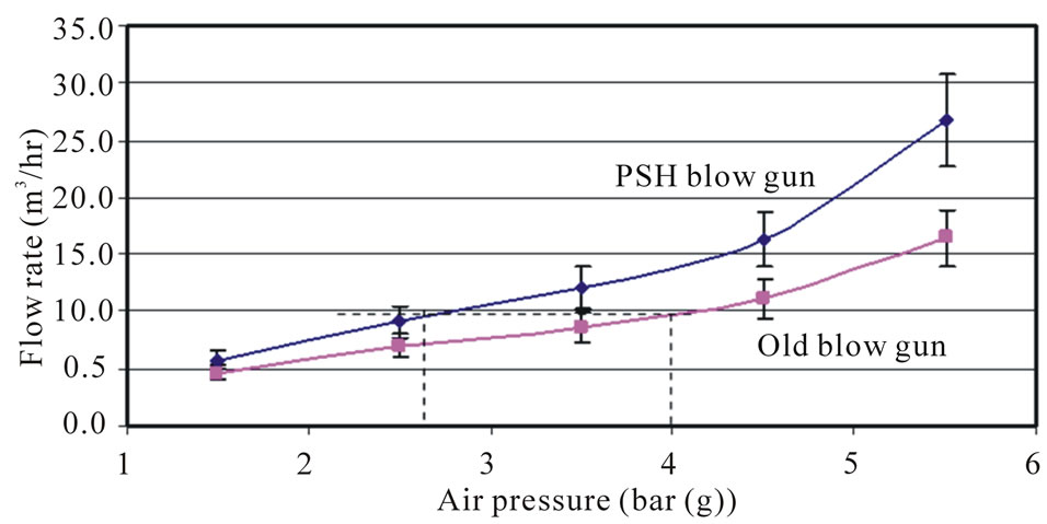
Figure 4. Comparison of old blow gun and PSH blow gun (new blow gun) performance.
and performance deteriorations.
4. Conclusions
Measurement of compressed air at usage point is important for maintenance and replacement of inefficient pneumatic end-use equipments. A test apparatus is developed based on measurement of reduction in compressed air pressure in a given time from a fixed volume cylinder. The test apparatus is easy to build and simple to operate in an industrial environment. The use of test apparatus is demonstrated in a foundry for performance characterization of a blow gun. The performance of an old and a new blow gun is measured with the test apparatus at different operating pressures. The experimental results indicates that the flow delivered by the old blow at 4 bar (g) can be delivered by the new blow gun at 2.7 bar (g). The coefficient of discharge estimated for the old gun is about 0.43 ± 0.1 and for the new gun is 0.75 ± 0.12. Based on measurement of flow it was possible to quantify the difference in the operating performance of the old and the new blow guns.
The test apparatus can be used for flow measurement of pneumatic end-use equipments for benchmarking. The test apparatus is also useful for measurement of overall compressed air consumption by different pneumatic enduse equipments together in a particular area or for a machine.
REFERENCES
- Y. Ming, “Air Compressor Efficiency in a Vietnamese Enterprise,” Energy Policy, Vol. 37, No. 6, 2009, pp. 2327-2337. doi:10.1016/j.enpol.2009.02.019
- Bureau of Energy Efficiency, “Energy Efficiency in Electrical Utilities,” Ministry of Power, New Delhi, 2003.
- Energy Efficiency and Renewable Energy, “Improving Compressed Air System Performance: A Sourcebook for Industry,” United States Department of Energy, Washington DC, 2003.
- R. N. James and J. J. K. Peter, “Compressed Air System Best Practice Programmer: What Needs to Change to Secure Long-Term Energy Savings for New Zealand,” Energy Policy, Vol. 37, No. 9, 2009, pp. 3400-3408. doi:10.1016/j.enpol.2009.04.047
- M. D’Antonio, G. Epstein, S. Moray and C. Schmidt, “Compressed Air Load Reduction Approaches and Innovations”, Proceedings of the Twenty-Seventh Industrial Energy Technology Conference, New Orleans, 2005.
- M. A. Koski, “Compressed Air Energy Audit ‘the Real Story’,” Energy Engineering, Vol. 99, No. 3, 2002, pp. 59-70. doi:10.1092/XKBG-8L3M-L90Y-7F5N
- S. K. Hajra Choudhary and A. K. Hajra Choudhary, “Workshop Technology: Volume I,” Media Promoters and Publishers, Mumbai, 1989.
- GIPL, “Ex-Blow Gun Air Product Catalogs for Compressed Products,” 2011. http://www.giplindia.com/exblow.htm.