International Journal of Nonferrous Metallurgy
Vol. 2 No. 2 (2013) , Article ID: 30469 , 5 pages DOI:10.4236/ijnm.2013.22008
Factors Research on the Influence of Leaching Rate of Nickel and Cobalt from Waste Superalloys with Sulfuric Acid
1Kunming Institute of Precious Metals, Kunming, China
2Sino-Platinum Metals Co. Ltd., Kunming, China
3State Key Laboratory of Advanced Technology of Comprehensive Utilization of Platinum Metals, Kunming, China
Email: fanxingxiang@tom.com, weizi314159@126.com
Copyright © 2013 Xingxiang Fan et al. This is an open access article distributed under the Creative Commons Attribution License, which permits unrestricted use, distribution, and reproduction in any medium, provided the original work is properly cited.
Received January 9, 2013; revised February 20, 2013; accepted March 2, 2013
Keywords: Waste Superalloys; Acid Leaching; Nickel; Cobalt; Leaching Rate
ABSTRACT
Unlike the reported leaching technologies of waste superalloys, the process of the “atomized spray-sulfuric acid leaching nickel and cobalt” technology was put forward in the present work according to the compositions of waste superalloys. The effects of sulfuric acid temperature, concentration, leaching time, stirring speed and size of superalloys on leaching of Ni and Co from waste superalloys have been mainly investigated, and the optimum leaching conditions were determined and reported. The leaching rates for nickel and cobalt were 96.68% and 96.63%, respectively, and the contents of nickel and cobalt in leaching slag were 6.77% and 0.96%, respectively. The obtained leaching solution containing Ni and Co could be used for production of Ni and Co products after removal.
1. Introduction
Ni and Co have excellent physical and chemical properties and mechanical properties, such as high temperature resistance, corrosion resistance, high strength and strong magnetism etc. The production of new materials [1], especially superalloys, play a key role in aviation, aerospace, and other relevant departments of industry. With the development of aerospace career, the demand of these new materials is increasing rapidly, i.e., the requirement of nickel and cobalt are also keeping increasing. However, the shortage of nickel and cobalt mineral resource is becoming more and more serious, secondary recovery of waste superalloys was thus put forward and studied in many countries to avoid wasting of the recyclable resources [2]. At present, the main extraction methods of cobalt and nickel include: acid leaching and high pressure acid leaching with sulfuric acid, hydrochloric acid, nitric acid, or ammonia leaching, chlorine leaching [3-12], and sulfide precipitation [13,14], electrolytic deposition method [15,16], and the carbothermal reduction [17], acid leaching following roasting [18] with hydrometallurgical process or pyrometallurgical process or pyro-hydro-metallurgical process. These processes are mainly aimed at treating various kinds of raw ore, waste ion battery, waste catalyst materials, relatively rare to treat waste superalloys materials. In this paper, after melting and milling the waste superalloy scrap, the authors investigated leaching of nickel and cobalt from waste superalloys with sulfuric acid directly, the influence factors on the leaching rates of nickel and cobalt ware mainly discussed based one the experimental results.
2. Experimental
2.1. Experimental Materials
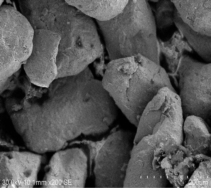
The materials used in this experiment were prepared by air-atomization. The average compositions of waste superalloys are listed in Table 1.which were determined with the methods of XRF, titration or FAAS. The SEM images in the Figure 1 shows the micrograph of waste superalloys. Figure 2 shows the waste superalloys mainly contain solid solution of Ni, Co, Al, Mo, Ta etc. as can be seen from the X-ray pattern shown in Figure 2. Acid insoluble components are mainly W, Mo, Ta etc.
 (a)
(a)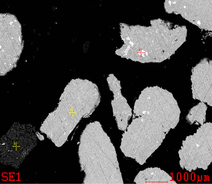 (b)
(b)
Figure 1. (a) The SEM images of waste superalloys powders; (b) Optical micrograph of waste superalloys (1. Ta, Nb, Ni; 2. Ni, Co, W, Al; 3. Ca, Si).
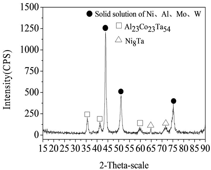
Figure 2. XRD pattern of waste superalloys.
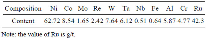
Table 1. Chemical compositions of waste superalloys (wt/%).
which were utilized in following process. The waste samples were crushed and screened under 80 - 120 mesh.
2.2. Experimental Methods
2.2.1. Experimental Process
The waste superalloys were melted at 1400˚C, and then made into powders with gas atomization. The powders were milled into different sizes for leaching with sulfide acid. The experimental flow chart of the leaching of Ni and Co from waste superalloys was shown in Figure 3.
2.2.2. Sulfide Leaching Tests
Sulfide leaching tests were carried out in 900 mL beakers. Add sulfide acid into the beaker and heat to a given temperature, then add the measured waste superalloys powders with mechanical stirring. During the reaction, constantly adding water to keep the volume unchanged. After the reaction, the volume of filtrate was measured, and the contents of Ni and Co in filter residue were analyzed.
2.2.3. Experimental Principle
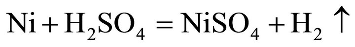
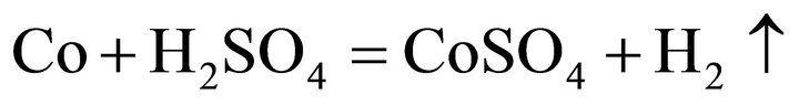
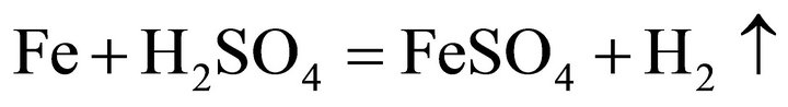
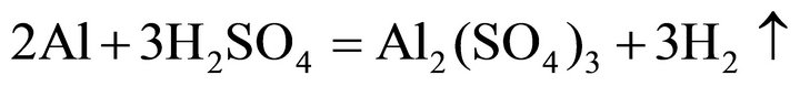
Considering the waste superalloys contain Ni, Co and Fe, the tests were performed with sulfide acid as Ni, Co and Fe could be dissolved by sulfide acid, producing sulfate and H2. During the leaching, the main reactions were considered as follows:
 (1)
(1)
 (2)
(2)
 (3)
(3)
 (4)
(4)
 (5)
(5)
3. Results and Discussion
3.1. Effect of the Temperature on Leaching Rate of Nickel and Cobalt
The effect of temperature on leaching rate of Ni and Co can be seen in Figure 4" target="_self"> Figure 4 and the leaching time is fixed as 5 hours, the sulfide concentration is fixed as 40 wt%, the stirring speed is fixed as 250 r/min, the size of the powder is fixed as −80 + 120 mesh. It can be seen in Figure 4 that the leaching rate of Ni and Co is influenced greatly by reaction temperature, the leaching rate of Ni and Co
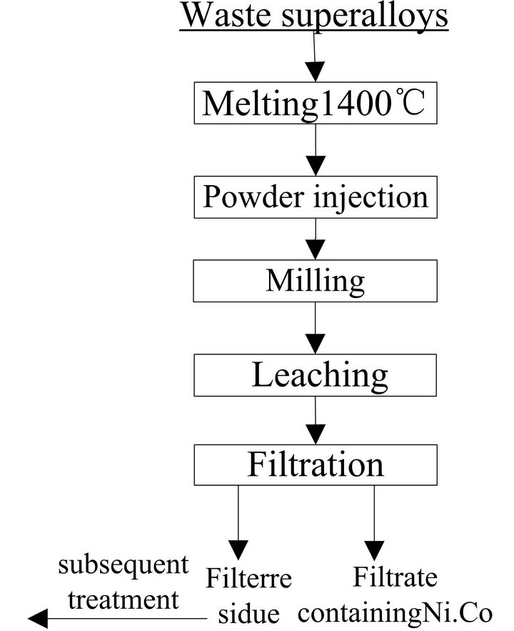
Figure 3. Flow chart of leaching Ni, Co from waste superalloys.
is as much as 96.68 wt% when temperature increased to 85˚C. Although the leaching rate can be improved slightly with increasing temperature, it is difficult to keep the temperature increasing as the energy will increase simultaneously. Therefore, the optimum temperature is 85˚C.
3.2. Effect of the Leaching Time on Leaching Rates of Nickel and Cobalt
Figure 5 shows the effect of leaching time on leaching rates of Ni and Co with other conditions are fixed. Figure 5 shows that at the beginning of leaching, the leaching rate of Ni and Co increase very quickly when leaching time increased to 5 hours, the leaching rate of Ni and Co can achieve above 96%, and then although with the leaching time increasing, the leaching rate increased slowly. Considering the efficiency and energy, 5 hours was chosen as the optimum leaching time.
Figure 6 shows that the peaks intensity of solid solution of Ni (containing Co, Al etc.) are decreasing with the time increasing, and some new different complicate chemical phase began to appear.
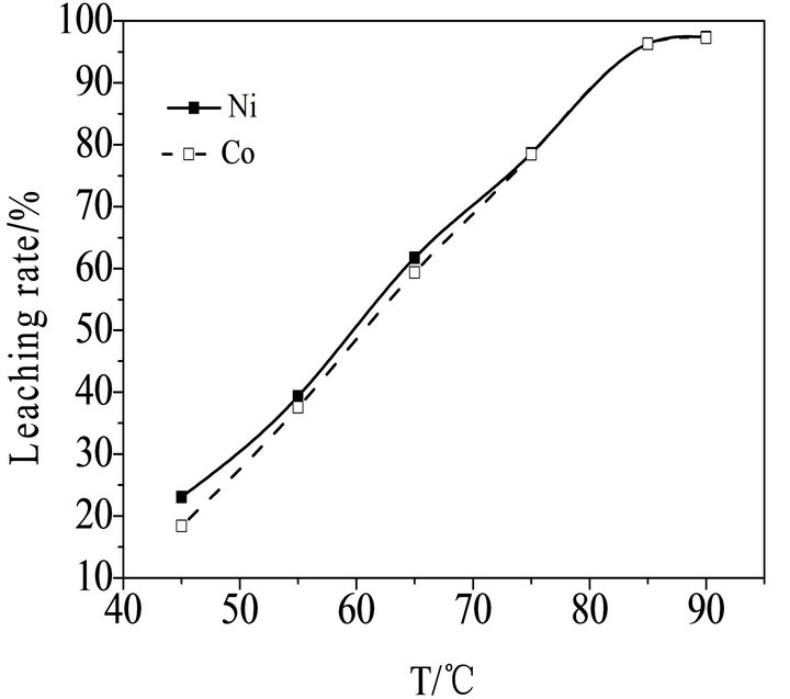
Figure 4. Effect of the temperature on leaching rate of nickel and cobalt.
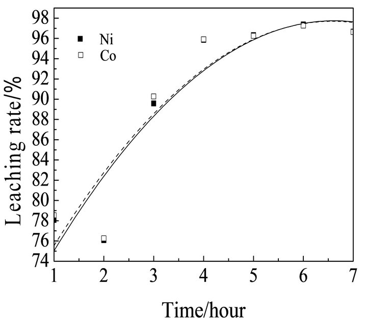
Figure 5. Effect of the leaching time on leaching rate of nickel and cobalt.
3.3. Effect of the Sulfuric Acid Concentration on Leaching Rates of Nickel and Cobalt
The effects of sulfuric acid concentration on leaching rates of Ni and Co were shown in Figure 7 with other conditions were fixed. Figure 7 shows that with increasing of sulfuric acid concentration, the leaching rate of Ni and Co increase obviously. When the sulfuric acid concentration increased to 40 wt%, the leaching rate are above 96%, while it can be seen that the increasing is relatively slow. Therefore the optimum sulfuric acid concentration is determined as 40 wt%.
3.4. Effect of the Stirring Speed on Leaching Rates of Nickel and Cobalt
Figure 8 shows that the effects of stirring speed on leaching rates of Ni and Co with other conditions are fixed. It can be obviously seen that, the leaching rate increase greatly initially with increasing the stirring speed. When the stirring speed increased to 250 r/min, the leaching rate of Ni and Co can achieve a satisfied result. But when the speed is increased again, the leaching rate of Ni and Co decreases greatly. Because the materials will be rotating with the solution, the effect of stirring is decreased.
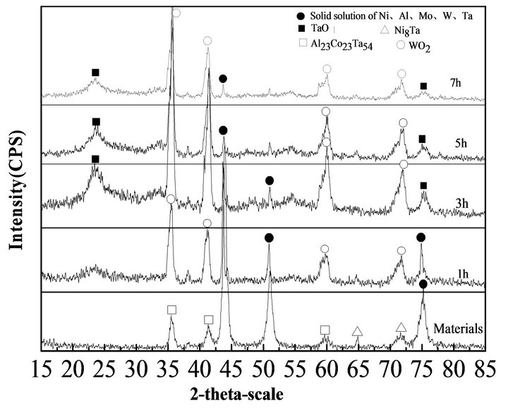
Figure 6. XRD pattern of material and leaching residue in different time.
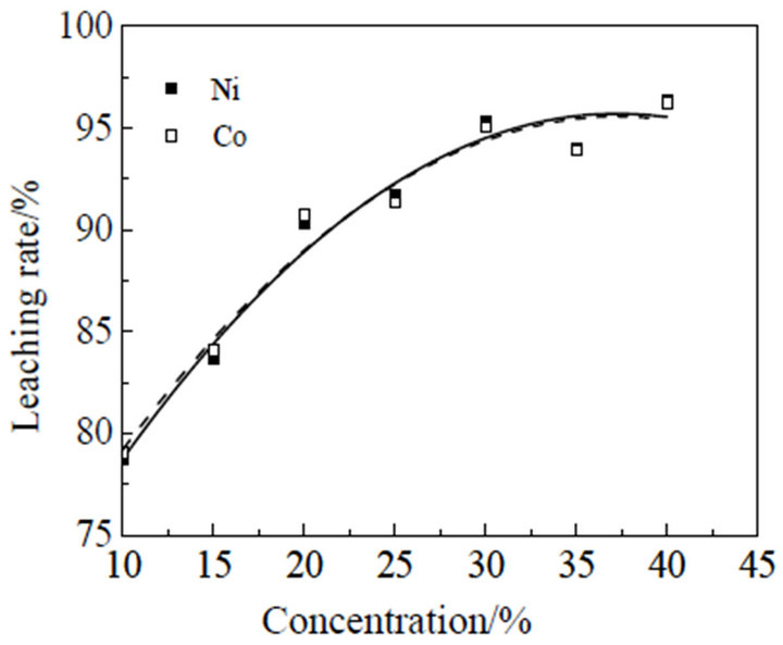
Figure 7. Effect of the sulfuric acid concentration on leaching rate of nickel and cobalt.
3.5. Effect of Particle Size on Leaching Rate of Nickel and Cobalt
It can be seen that the effect of particle size on leaching rate of Ni and Co in Figure 9. Theoretically, the smaller size of the materials, the easier to be heat and mass transfer, and the higher leaching rate. Figure 9 shows that the leaching rate of Ni and Co is increasing slowly when the particle size is increased from 40 - 80 mesh to 160 - 200 mesh. When the size is increased to 200 - 250 mesh, the leaching rate will increase slowly. But it is hard to prepare small particle size, and alsotime-consuming, because the leaching rate of Ni and Co has achieved 96% when the particle size is 80 - 120 mesh. Therefore the optimum size of materials is determined as 80 - 120 mesh.
4. Results Analysis of Residues of Leaching Ni and Co with Sulfuric Acid
The chemical compositions of leaching residues are listed in Table 2" target="_self"> Table 2. It can be seen that the contents of Ni
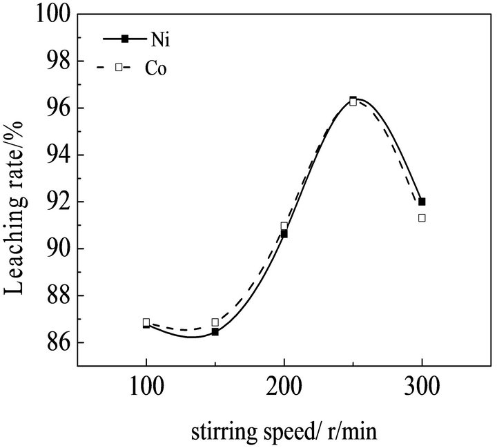
Figure 8. Effect of stirring speed on leaching rate of nickel and cobalt
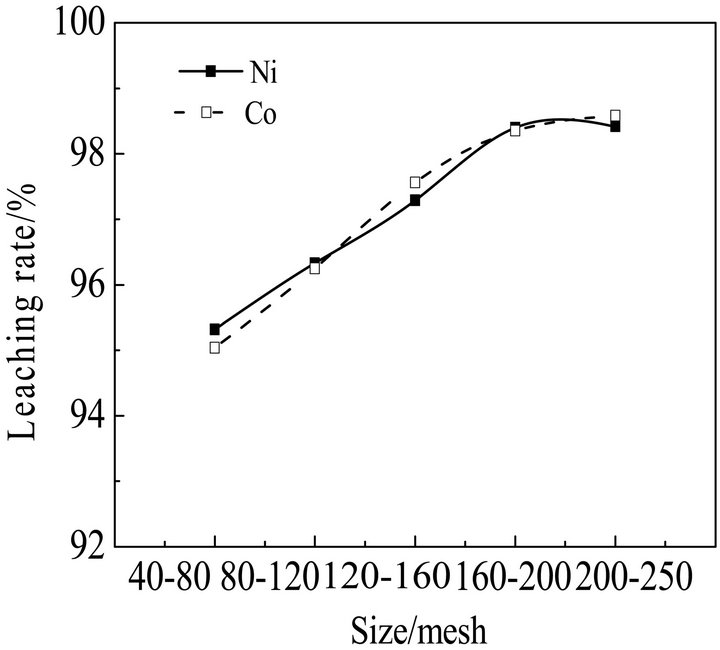
Figure 9. Effect of size on leaching rate of nickel and cobalt.
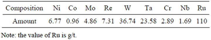
Table 2. Chemical compositions of leaching residues (wt/%).
and Co were obviously decreased, and the contents of W and Ta etc. were enriched for recycling in the subsequent process. In comparison with Figures 1(a) and 10, it can been seen that the particle size becomes much smaller.
The XRD analysis in Figure 11 indicates that the peaks of Ni, Co and Al etc. decreased greatly compare to the Figure 1(b). The peaks of W and Ta etc. increased, it shows that W and Ta etc. were enriched well in the residues of leaching.
5. Conclusions
1) The optimum leaching conditions for leaching Ni and Co from superalloys with sulfuric acid are reported as T = 85˚C, sulfuric acid concentration = 40 wt%, leaching time = 5 h, stirring speed = 250 r/min, and materials particle size = 80 - 120 mesh. The leaching rate of Ni and Co can be at least 96% under this optimum leaching conditions. The contents of Ni and Co in leaching slags were measured as 6.77% and 0.96%, respectively. The leaching solution containing nickel and cobalt could be used for production of Ni and Co products.
2) This study investigated the optimum leaching conditions of Ni and Co from waste superalloys and supplies the important reference data for recycle of other waste superalloys.
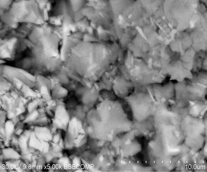
Figure 10. The SEM graph of leaching residues.
Figure 11. XRD pattern of leaching residues.
6. Acknowledgements
The project was sponsored by National High Technology Research and Development Program of China (863 Program, 2012AA063204).
REFERENCES
- A. L. Li, X. R. Zeng and L. M. Cao, “Current Status of Research on High Temperature Materials for Advanced Aircraft Engines,” Materials Review, Vol. 17, No. 2, 2003, pp. 26-28.
- Q. L. Su, Z. W. Shi and J. Hunsaker, “Status and Consideration of Recycling of Superalloys in Our Country,” Non-Ferrous Metals Recycling and Utilization, Vol. 4, 2006, pp. 19-20.
- Y.-F. Shen, W.-Y. Xue and W.-Y. Niu, “Recovery of Co(Ⅱ) and Ni(Ⅱ) from Hydrochloric Acid Solution of Alloy Scrap,” Transaction of Nonferrous Metals Society of China, Vol. 18, No. 5, 2008, pp. 1262-1268.
- J. H. Li, X. H. Li and Q. Y. Hu, “Study of Extraction and Purification of Ni, Co and Mn from Spent Battery Material,” Hydrometallurgy, Vol. 99, No. 1-2, 2009, pp. 7-12.
- G. J. van Tonder and P. J. Cilliers, “Cobalt and Nickel Removal from Zincor Impure Electrolyte by Molecular Recognition Technology (MRT)-Pilot Plant Demonstration,” The Journal of The South African Institute of Ming an Metalleurgy, 2002, pp. 11-18.
- Z. J. Yu, Q. M. Feng and L. M. Ou, “Leaching of Cobalt Bearing Metallic Matte in Sulfhuric Acid at Normal Pressure,” Journal of Central South University (Science and Technology), Vol. 37, No. 4, 2006, pp. 675-679.
- M. V. Rane, V. H. Bafna and R. Sadanandam, “Recovery of High Purity Cobalt from Spentammonia Cracker Catalyst,” Hydrometallurgy, Vol. 77, No. 3-4, 2005, pp. 247-251. doi:10.1016/j.hydromet.2004.12.004
- Y. J. Zheng, H. Teng and H. Q. Yan, “Nitric Acid Oxidation Leaching of Cobalt from Refractory High-Arenic Cobalt Ores,” The Chinese Journal of Nonferrous Metals, Vol. 20, No. 7, 2010, pp. 1418-1423.
- N. J. Kang, “Development of Application of Hot Pressure Leaching Technology in Recovery of Nickel and Cobalt in China,” China Nonferrous Metallurgy, Vol. 24, No. 2, 1995, pp. 1-7.
- J. H. Liu, H. R. Zhang and R. X. Wang, “Process of Ammonium Leaching Oxidation Ore of Cobalt and Copper at High Pressure,” Chinese Journal of Rare Metals, Vol. 36, No. 1, 2012, pp. 149-153.
- Y. F. Shen, W. Y. Xue and W. Li, “Selective Recovery of Nickel and Cobalt from Cobalt-Enriched Ni-Cu Matte by Two-Stage Counter-Current Leaching,” Separation and Purification Technology, Vol. 60, No. 2, 2008, pp. 113-119. doi:10.1016/j.seppur.2007.08.010
- X. C. Hou, L. S. Xiao and C. J. Gao, “Experimental Study on Leaching of Nickel and Cobalt from Waste High-Temperature Ni-Co Alloys,” Hydrrometallurgy of China, Vol. 28, No. 3, 2009, pp. 164-169.
- Y. M. Zhou and B. L. Hu, “Nickel and Cobalt Recovered from Cobalt-Nickel Matte Leaching Lixivium,” Nonferrous Metals (Extractive Metallurgy), Vol. 6, No. 4, 2012, pp. 11-13.
- Y. B. Xu, Y. T. Xie and J. S. Liu, “Enrichment of Valuable Metals from the Sulfuric Acid Leach Liquors of Nickeliferous Oxide Ores,” Hydrometallurgy, Vol. 95, No. 1-2, 2009, pp. 28-32.
- N. Pradhan, P. Singh and B. C. Tripathy, “Electrowining of Cobalt from Acidic Sulphate Solutions-Effect of Chloride Ion,” Minerals Engineering, Vol. 14, No. 7, 2001, pp. 775-783. doi:10.1016/S0892-6875(01)00072-3
- W. P. Zhang, “Study on the Processing of Low-Co Cemented Carbide Scraps by Electrochemical Method,” Cenmented Carbide, Vol. 23, No. 2, 2006, pp. 107-109.
- R. T. Jones, G. M. Denton and Q. G. Reynolds, “Recovery of Cobalt from Slag in a DC Arc Furnace at Chambishi, Zambia,” The Journal of the South African Institute of Mining and Metallurgy, 2002, pp. 5-10.
- C. Arslan and F. Arslan, “Recvery of Copper, Cobalt and Zinc from Copper Smelter a Converter Slags,” Vol. 67, No. 1-3, 2002, pp. 1-7.