International Journal of Modern Nonlinear Theory and Application
Vol.3 No.3(2014), Article
ID:47871,15
pages
DOI:10.4236/ijmnta.2014.33012
Control of Doubly Fed Induction Generator Supplied via Matrix Converter for Wind Energy Conversion System
Zakaria Kara, Kamel Barra
Electrical Engineering, Larbi Ben M’hidi University, Oum El Bouaghi, Algeria
Email: zakkka@yahoo.fr, barakamel@yahoo.fr
Copyright © 2014 by authors and Scientific Research Publishing Inc.
This work is licensed under the Creative Commons Attribution International License (CC BY).
http://creativecommons.org/licenses/by/4.0/


Received 28 May 2014; revised 29 June 2014; accepted 8 July 2014
ABSTRACT
The present paper deals with the modeling and control of Wind Energy Conversion System WECS based Doubly Fed Induction Generator DFIG using the slip energy recovery principle. The proposed drive system uses a Matrix Converter (MC) to transfer the slip energy of the rotor into the mains instead of using cascaded ac-dc-ac converter whilst the stator side is fixed to the grid. Operation at both sub-synchronous and super-synchronous regions is possible with the proposed drive system. The different level control strategies for maximum power point tracking and active-reactive power are discussed. Simulation results of the proposed doubly fed induction generator drive system show the good performance of the control system strategy for both transient and steadystate conditions.
Keywords:WECS, DFIG, Tip Speed Ratio (TSR), PI Control, Matrix Converter

1. Introduction
Wind energy conversion systems (WECS) are generally equipped with Doubly Fed Induction Generator (DFIG) functioning at variable speed. For fixed-pitch turbines operating in partial load, maximum energy capture available in the wind generator can be achieved if the turbine rotor operates on the Optimal Regime Characteristic (ORC). This regime can be obtained by tracking some target variables: the optimal rotational speed, depending proportionally on the wind speed, or the optimal rotor power [1] [2] .
Several configurations for variable speed wind energy conversion system based on Doubly Fed Induction Generator are available in the literature. We cite some examples; the first one is the slip energy dissipation: here the stator side is directly fixed to the grid whereas the rotor side is connected to a rectifier converter. In the output of this converter, a resistive load is connected via a DC-DC converter. Its main role is keeping the DFIG in the stable part of torque-speed characteristic, and this is achieved by varying the slip energy to feed the resistive load, where the rotor energy changes according to speed variation. The main disadvantage of this configuration is its bad efficiency especially when the slip energy increases to an important value [3] .
The second topology is Kramer structure: in order to minimize the losses caused by the previous configuration, a DC-DC converter and resistive load are replaced by DC-AC inverter to inject the slip energy into the gid. So this structure allow the generation only in hyper synchronous regime [3] .
The third topology known as Scherbius structure, employs a DFIG using a back-to-back PWM converters or line commutated cycloconverter connected between rotor side and mains [1] . The ac-dc-ac converter requires two-stage power conversion, namely rectification and inversion, which demands a complicated control strategy and large dc link capacitors, making the system bulky and expensive. In addition, the system allows the motor operating only at subsynchronous speed region if uncontrolled rectifier is used. Also, difficulty is experienced near synchronous speed when the slip-frequency back emfs are insufficient for natural commutation. Whereas cycloconverters cause additional harmonic pollution both at the supply side and the motor side since their output contains several harmonic frequencies, and the input power factor is very low due to natural commutation [4] .
In this paper, by numerical simulation we investigate the role of Maximum Power Point Tracking (MPPT) controller in a variable speed WECS to control the power conversion. In this way, the classical PI control is widely used, owing its popularity to some key features. Its design procedure is quite simple. It requires little feedback information and gives rise to solutions easy to implement, with intrinsic robustness properties which can be employed over most plants having smooth models [2] .
The configuration of WECS is based on a DFIG well adapted for large speed variation range fed by a Matrix Converter (MC) used as the interface between the electrical generator and the grid side. Its main purpose is to control the speed and the rotor side currents of wound-rotor induction motor. Such a configuration can offer the advantages given by back-to-back converters while converting ac power in a single stage and eliminating the large dc link capacitor. In addition, the control scheme required by ac-ac conversion scheme is simpler than that of a two-stage power conversion [5] . Moreover it provides easier operation at unity power factor. Therefore, it is connected to a three-phase source through the input filter Lf, Rf, Cf. This filter has two main purposes:
• To avoid the generation of overvoltages, produced by the short-circuit impedance of the power supply, due to the fast commutation of currents;
• To eliminate high-frequency harmonics in the input currents.
2. Modeling
2.1. Wind Turbine Characteristics
Several variable-speed WECS configurations are being widely used in literature. The studied configuration in the present paper is a fixed pitch Horizontal Axis Wind Turbines HAWT. The power characteristics of the wind turbine of the studied system have a maximum for each wind speed. All these maxima form the so-called Optimal Regime Characteristics ORC given by Figure 1.
The studied configuration has a power coefficient (aerodynamic efficiency)  depending on the Tip Speed Ratio TSR (i.e., the ratio between the blades’ peripheral speed and the wind speed:
 ) and having a maximum for
 ![]() (see Figure 2). The availible mechanical power on the turbine shaft is [2] :
(see Figure 2). The availible mechanical power on the turbine shaft is [2] :
 (1)
(1)
The power coefficient  is then given by [6] :
 (2)
(2)
 (3)
(3)
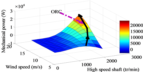
Figure 1. Power captured by a wind turbine vs. high speed shaft.
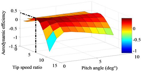
Figure 2. Aerodynamic efficiency versus tip speed ratio.
Figure 2 depicts the aerodynamic efficiency  versus the tip speed ratio
 ![]() for different values of pitch angle
for different values of pitch angle ![]() where it is clear to see that its maximum value
where it is clear to see that its maximum value ![]() for
for ![]() and
and ![]() (dashed point).
(dashed point).
2.2 DFIG Model
The equations that describe a doubly fed induction generator are identical to those of the squirrel cage induction generator; the only exception is that the rotor winding is not short-circuited. We assume balanced voltages and non-ground connection points regime. Two orthogonal axes are defined, the ![]() (direct axis) and
(direct axis) and ![]() (quadrature axis).
(quadrature axis).
In order to obtain a decoupled control of active-reactive powers, the DFIG model requires all quantities to be expressed in the stator flux reference frame where [7] :
 (4)
(4)
The rotor voltage expressions are simplified as:
 (5)
(5)
The stator current expressions are:
 (6)
(6)
The expression for the electrical torque:
 (7)
(7)
The stator active-reactive powers expressions are:
 (8)
(8)
Note that:
 (9)
(9)
where  are electrical parameters of the DFIG and p is number of pole pair.
2.3. Matrix Converter Model
Despite some drawbacks such as high number of power semiconductor devices, the limitation of maximum load voltage to 86% of the supply voltage, no need for energy storage element, the matrix converters have received recently a wide attention especially in motion control. The three-phase to three-phase direct matrix converter has been extensively researched due to its potential as a replacement for the traditional AC-DC-AC converter in AC motor drives for the following benefits [8] :
• Adjustable input displacement factor, irrespective of the load;
• The capability of regeneration (four-quadrant operation);
• High quality input and output waveforms;
• The lack of bulky and limited lifetime energy storage components, such as electrolytic capacitors.
The MC converter is based on bi-directional switches and replaces the rectifier, inverter and energy storage element of the AC-DC-AC converter in only one stage thereby reducing the size of the conversion chain but increasing the control complexity.
It must be mentioned that the load current must not be interrupted abruptly, because the inductive nature of the load will generate an important overvoltage that can destroy the components. In addition, operation of the switches cannot short-circuit two input lines, because this switching state will originate short circuit currents [9] . These restrictions can be expressed in mathematical form by the following equation:
 (10)
(10)
Referenced to the neutral point N, the relation between the load and input voltages of the DMC is expressed as:
 (11)
(11)
where  is the instantaneous transfer matrix. The input and load voltages can be expressed as vectors as follows:
 (12)
(12)
the relation of the voltages is given by

Applying Kirchhoff’s current law to the switches, the following equation can be obtained:
 (13)
(13)
Considering the current vectors
 (14)
(14)
the equation for the current is
 (15)
(15)
where ![]() is the transpose of matrix
is the transpose of matrix .
.
Figure 3 depicts the MC current and voltage inputs and Figure 4 shows the DMC current and voltage outputs for a three phase R-L load where one can see that the input currents are highly distorted due to commutation switches whereas in Figure 5; a Fourier spectrum of MC current where it is easy to see the fundamental (50 Hz) and the dominant switching frequency (6 kHz).
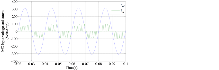
Figure 3. MC current and voltage input.
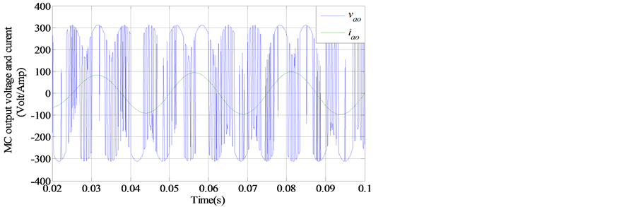
Figure 4. MC current and voltage output.
2.4. Input Filter Model and Design
The input filter model is shown in Figure 6, and can be described by the following continuous-time equations:
 (16)
(16)
where ,
,  and
and  are the inductance, the resistance and capacitance of the line filter. The continuoustime filter model can be rewritten as:
 (17)
(17)
with
 (18)
(18)
The filter parameters are chosen in order of high rank harmonics eliminating with into account the next considerations [9] :
• The cut-off frequency of the filter should be lower than the switching frequency and higher than the fundamental frequency of the input AC source.
• The input power factor should be kept maximum for a given minimum output power.

Figure 5. MC current and voltage output.
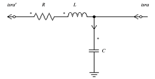
Figure 6. Single stage input filter.
• The lowest volume and/or weight of capacitor and chokes is used in the design procedure.
• The voltage drop in the inductor should be at its minimum value.
Figure 7 shows that when using a RLC filter with efficient procedure design, the input current of the MC becomes well filtered and perfectly in phase with the input voltage working at unity power factor. As a consequence, the THD of the filtered current avoids undesired high frequency harmonics as given by Figure 8.
3. Control Strategy
To ensure an optimal regime it must manipulate the aerodynamic efficiency coefficient by regulating the speed generator in order to keep  this is effectuated by injecting a speed setpoint derived from the relation (19), then a torque reference is generated. From the relationship between the torque and stator active power (9), a set point for the generated power is derived.
3.1. MPPT Control
The DFIG torque is controlled to maintain the tip speed ratio at its optimal value. The speed setpoint is derived from the optimal tip speed ratio as:
 (19)
(19)
where  are high and low speeds shaft (HSS, LSS) of the gearbox.

Figure 7. Current and voltage source after filtering.

Figure 8. Current and voltage source after filtering.
PI Control
Figure 9 illustrates the control diagrame using the PI regulator in its simplest way, where![]() ,
, ![]() are total inertia and mechanical friction coeficients:
are total inertia and mechanical friction coeficients:
The closed loop transfer function is:
 (20)
(20)
In order to obtain a first order system behavior:
 (21)
(21)
the controller parameters’ are expressed as:

3.2. Power Control
Complete model scheme of the studied drive system is illustrated by Figure 10 where the active power set point is derived from torque reference signal which results from the speed tracking loop however the reactive power is settled to 0 in order to keep a unity power factor in the generated power:
 (22)
(22)
4. Simulation Results
The numerical simulations are evaluated on Matlab-Simulink hardware for 5 seconds in several conditions for the wind speed variations as it is given by the profile of Figure 11 for both sub synchronous mode (0.6 s - 1.2 s) and super synchronous mode.
Figures 12-18 illustrate respectively the high speed shaft tracking of the DFIG, the electromagnetic torque; the aerodynamic torque, the aerodynamic power, the optimal regime characteristic; the tip speed ratio TSR and the aerodynamic efficiency  of the wind energy conversion chain. It can be seen that the control aims are performed in terms of speed tracking and oscillation around optimal power points providing good energy conversion with high efficiency since the tip speed ratio and aerodynamic efficiency (the two most energy conversion quality indicating parameters) oscillate around their optimal values.
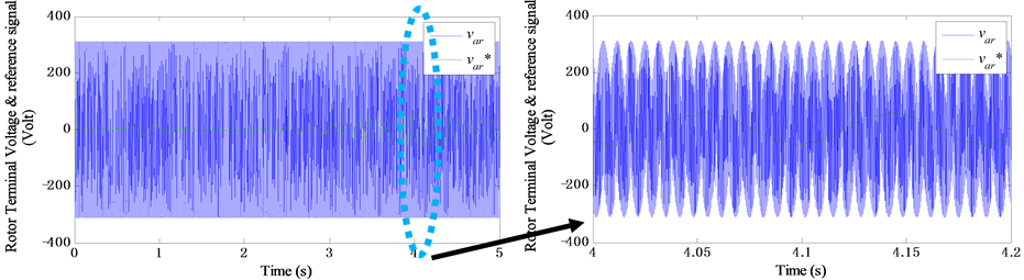
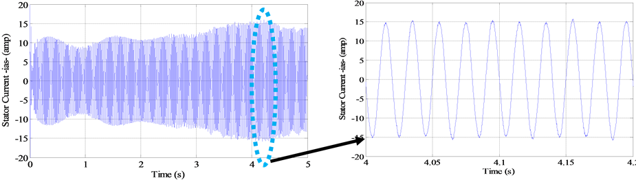
Figures 19-22 depict the stator active and reactive powers injected in the grid via the RLC filter, the MC output voltage which is the rotor voltage  with its zoom, the stator current
  and the rotor currents (MC output currents)
 , and their zooms. On these figures one can see that all these quantities have a profile that follows the wind speed variations. Figure 23 presents the output line voltage of the MC (rotor line voltage). The WECS works at unity power factor since the stator reactive power is fluctuating around 0.
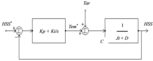
Figure 9. PI control scheme.

Figure 10. Grneral control schem.

Figure 11. Wind speed profile.
Also, Figures 24-26 depict the MC input current, with input voltage in both sub-synchronous regime and hyper-synchronous regime, in the sub-synchronous mode. They are in phase, but when HSS exceeds the synchronous speed they become shifted with π. The next Figure 27 and Figure 28 present the unfiltered stator-rotor current  with MC input voltage
  and the filtered stator-rotor current
  with the grid source voltage
 . On these figures, it is clear to see that a significant power quality enhancement is achieved by the
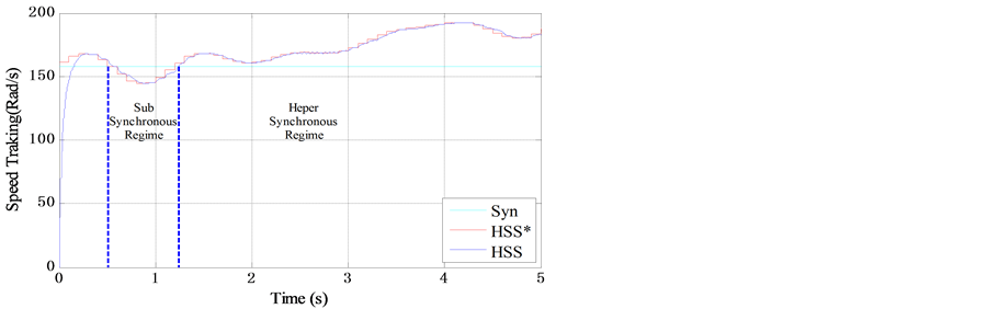
Figure 12. Speed shaft tracking.
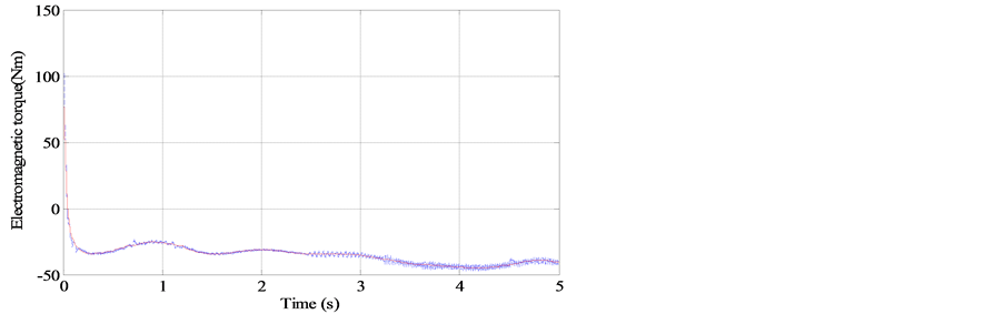
Figure 13. Electromagnetic torque tracking.

Figure 14. Aerodynamic torque.

Figure 15. Aerodynamic power.

Figure 16. Tip speed ratio compared with the optimal value.
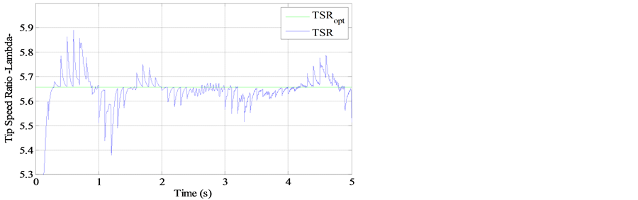
Figure 17. Tip speed ratio compared with the optimal value.
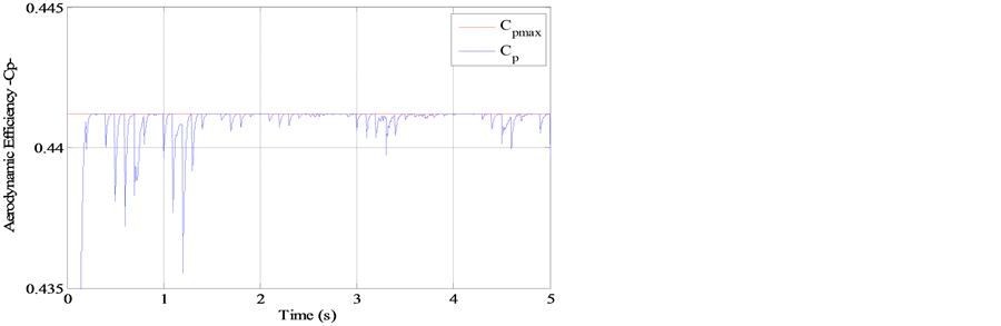
Figure 18. Aerodynamic efficiency.

Figure 19. Active and reactive generated power.
 (a) (b)
Figure 20. (a) Rotor terminal voltage and its reference; (b) Zoom in Rotor terminal voltage—MC voltage output.
 (a) (b)
Figure 21. (a) Stator current ias; (b) Zoom on stator current ias.
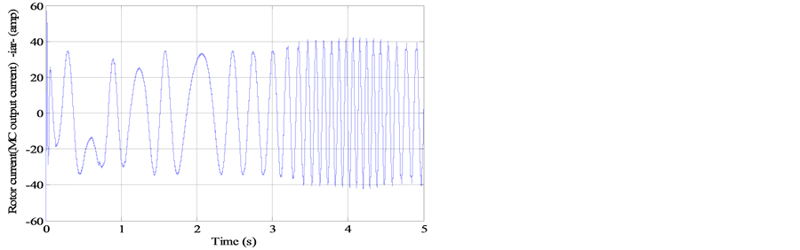
Figure 22. Rotor current iar (MC output current).

Figure 23. Rotor line voltage vabr.
 (a) (b)
Figure 24. (a) MC input current iari; (b) Zoom on MC input current iari.

Figure 25. Rotor input current and input voltage of the MC.
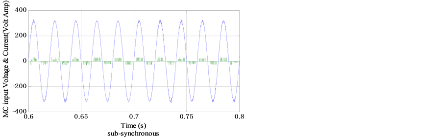
Figure 26. Rotor input current and input voltage of the MC.
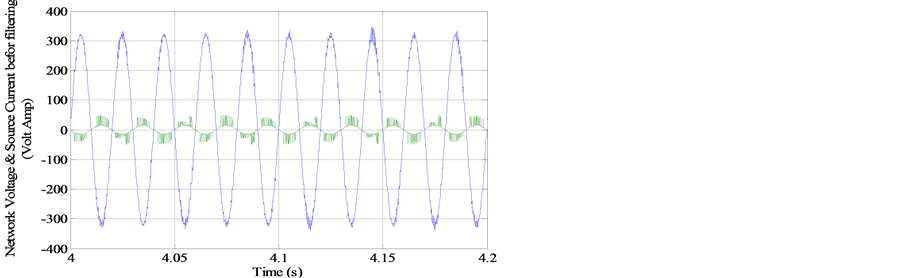
Figure 27. Unfiltered stator current and voltage isra.
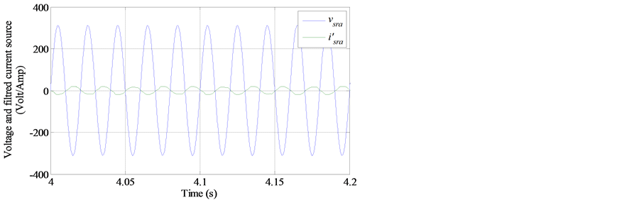
Figure 28. Filtered stator current and voltage i’sra.

Figure 29. Fourier transform for the unfiltered current source isra.

Figure 30. Fourier transform for the filtered current source i’sra.
RLC filter proofed by the THD for both unfiltered and filtered current signals where it is observed (Figure 29) that the THD is reduced from THDi’sra = 0.4808 (48%) for the unfiltered current to THDi’sra = 0.0482 (4.82%) (Figure 30) for the filtered current by eliminating all harmonics that appear in the grid current specter.
5. Conclusions
In this paper, we investigate by simulation results the effectiveness of a proposed control method for maximizing the power harvested from the wind. A general model and control laws are analyzed and simulated for optimal power production of a variable speed wind turbine equipped with a doubly fed induction generator. The control system is based on traditional PI controllers. The supply side converter is a matrix converter with SVM modulation technique.
Over the different simulation results, it is observed that the performance of the WECS system is enhanced in terms of tracking speed and torque, oscillations around optimal power points and especially low current distortion in the grid side obtained by inserting a RLC filter before connecting with the grid.
References
- Quaschning, V. and Jourdan, H. (2010) Renewable Energy and Climate Change. John Wiley & Sons, Hoboken.http://dx.doi.org/10.1002/9781119994381
- Munteanu, L., et al. (2008) Optimal Control of Wind Energy Systems; towards a Global Approach. Springer-Verlag, Berlin.
- Poitiers, F. (2003) Etude et Commande Des Génératrices Asynchrones pour l’utilisation de l’Energie Eolienne. Doctorat Thesis, Nantes University, France Décembre, 26-32.
- Musgrove, P. (2010) Wind Power. Cambridge University Press, Cambridge.
- Munteanu, L., Bacha, S., Bratcu, A.I., Guiraud, J. and Roye, D. (2008) Energy-Reliability Optimization of Wind Energy Conversion Systems by Sliding Mode Control. IEEE Transactions on Energy Conversion, 23.
- Ackermann, T. (2005) Wind Power in Power Systems. John Wiley & Sons Ltd., Stockholm.http://dx.doi.org/10.1002/0470012684
- Abad, G., Miguel, J.L. and Iwanski, A.R.L.M.G. (2011) Doubly Fed Induction Machine. John Wiley & Sons, Inc., New Jersey.
- Neft, C.L. and Shauder, C.D. (1992) Theory and Design of a 30-hp Matrix Converter. IEEE Transactions on Industry Applications, 28, 546-551. http://dx.doi.org/10.1109/28.137434
- Kazmierkowski, P., Krishnan, R. and Blebjerg, F. (2002) Control in Power Electronics. Academic Press of Elsevier, San Diego.
Appendix
The system used for validation has the following features:
• type: fixed pitch HAWT turbine:
Rated wind speed v = 9.5 m/s, R = 3 mEnergetic performance: maximal value of the power coefficient max  at optimal tip speed ratio
 Constant air density: ρ = 1.25 Kg/m3Electromechanical features: Jt = 0.1 Kg·m2D = 6.73 × 10⁻³ N·m·s−1Gearbox coefficient G = 10.
• Generator 50 Hz, 380 V, 7.5 kW, 1440 rpm, p = 2.