Open Journal of Fluid Dynamics
Vol.05 No.02(2015), Article ID:56851,5 pages
10.4236/ojfd.2015.52016
Hydrodynamic Assessment of Increasing the Energy Efficiency of Trawler Propulsion with a Draft Tube
Jonas Eliasson1, Elias B. Eliasson2, Halldor S. Eliasson3
1Faculty of Civil and Environmental Sciences VRII, University of Iceland, Reykjavík, Iceland
2National Power Company of Iceland, Reykjavík, Iceland
3School of Marine Engineering, Technical College, Reykjavík, Iceland
Email: jonase@hi.is, eliasbe@simnet.is, hsmarinn@gmail.com
Copyright © 2015 by authors and Scientific Research Publishing Inc.
This work is licensed under the Creative Commons Attribution International License (CC BY).
http://creativecommons.org/licenses/by/4.0/


Received 18 March 2015; accepted 30 May 2015; published 2 June 2015
ABSTRACT
The economy of the fishing industry is suffering from high fuel prices. Considerable efforts are invested in methods to increase the energy efficiency of fishing vessels and reducing the oil consumption per kilo of catch that may be as high as 0.6 to 0.7 liter oil per kilo catch. It is primarily the fact that sailing and fishing are on two very different speeds that cause these high fuel consumptions. This is called the two-speed problem and it is the trawlers that are hit hardest by it. The essence of the two-speed problem is that a hydraulic efficiency of only 28% can be expected in trawling speed, when it would be 67% if the ship is sailing at optimum speed all the time. Hydrodynamical analysis shows that an average hydraulic efficiency of only 41% can be expected for a trawler. There is no simple remedy for this, but it is possible to use a technology developed in the hydropower industry, i.e. a draft tube, or a diffuser, to recover energy that would otherwise be lost when trawling. A draft of tube the same length as the propellers diameter could mean fuel savings of 10%, a draft tube twice as long 20%. The difficulty is to find a way to get the draft tube out of the water during sailing with a vessel-specific mechanical design that is not a part of the fluid dynamics of the problem and not discussed in the paper.
Keywords:
Trawler, Energy Efficiency, Hydrodynamic Assessment, Fuel Economy, Draft Tube

1. Introduction
In selecting the propulsion system for a ship, the sailing speed is a very important factor. With today’s oil prices, economic performance depends to a large extent on the energy efficiency of the vessel and knowing the sailing speed, the propulsion system can be optimized. In practical operations of the ship this sailing speed is maintained as long as possible.
In marine engineering this is standard practice. Ships can be designed with maximum energy efficiency on one speed, but not two. It is therefore the constant problem in trawler design that there is not one prevailing sailing speed but two, one in sailing, then the other in trawling. If the system is running on optimum efficiency in sailing, as is most common, the energy efficiency in trawling is poor. If the energy efficiency is good in trawling, which is rare, energy efficiency in sailing is poor. If the system is designed with the best efficiency at some intermediate speed, a choice unknown to these authors, the ship would be running on poor efficiency in both sailing and trawling.
The energy consumption of the world’s fishing fleet is a permanent problem that needs to be tackled simply by improving the energy efficiency of the fishing vessels. It has been suggested that the average energy consumption in fishing is around 0.6 to 0.7 liter oil per kilo un-gutted cod catch [1] ; this is simply too much.
Authors generally agree that fuel savings are necessary in the fishing fleet and there are many ways to achieve this goal [2] . None of the fuel savings methods mentioned by him attack the two-speed problem specifically.
Considerable savings are sometimes possible by improving the fishing gear design. This is a very vessel specific operation. [3] built new vessels and tested all aspects of them and the new fishing gear in a laboratory flume. Full-scale trials were then carried out with both vessels and their performance compared with the existing ones with the result that a potential 27% increase in economical result was possible. This is a considerable improvement, but the two-speed problem is still there.
Many fishing vessels propulsion systems with fixed pitch propellers are obsolete and energy-intense [4] . It is generally admitted that the fuel consumption can be shared as follows: 1/3 is used for the trawler (propelling the ship when steaming or during the fishing operations); 2/3 is used to tow the trawl [5] .
[6] discussed a great variety of possibilities to increase the energy efficiency of fishing vessels in a very thorough report. Speed reduction in sailing is mentioned as one of the important factors to consider. This is of course an obvious remedy to the two-speed problem. The closer to each other the two speeds are, the less acute is the two-speed problem. However, this is a fact everybody knows, but the sailing speed of modern trawlers is not on the decrease. The longer time to sail to the fishing grounds and home again is also expensive as it reduces active fishing time, thus reducing the overall economic performance.
In the following we shall investigate the hydrodynamics of the two-speed problem of trawlers and point out a possible solution. The practical problems of construction are left out of the discussion.
2. Hydrodynamic Efficiency of Propulsion
It can easily be demonstrated that the overall efficiency of propulsion, eh, is composed of following partial efficiency values.
 .
.
Here we only discuss the slip stream efficiency ess. What this coefficient tells us is how much of the energy in the propellers slip stream is actually used in the propulsion of the ship. The rest of the energy is lost, either in the propeller action or in the power plant. Of all these coefficients we only discuss ess here. This is the efficiency in utilizing the energy delivered by the propeller to the water in propulsion of the ship.
We consider two cases; the first is sailing at full speed and the second trawling at full power. There are of course other cases that may be considered as well, but comparing the efficiency results for these two cases demonstrate the problem sufficiently and the possible remedy.
3. Case One: Full Speed Ahead
By including the ship in a control volume where the mass flow in the slip stream (m kg/s) is the inflow and the outflow, we obtain the following formula for the thrust in the slip stream
 (1)
(1)
VC is the component of the velocity of the water leaving the propeller projected on the axis of the ship and VA is similarly the velocity of the water along the axis of the ship, which enters the enclosed control volume. AC is the area of the propeller and ρ is the density of seawater. Then we can use m = ρACVC. VA will be very much the same as the speed of the ship and this will be used in the following. To reduce VA a little saves fuel, but may decrease fishing. The difference in fuel consumption will always be small and is not considered significant in the following treatment. This holds for both propulsion cases.
In the first propulsion case the energy delivered to the slipstream by the propeller is EN Joule/s, but only the portion essEN is used for advancing the ship. In steady state the thrust is TF, equal to the resistance of the ship’s hull and the energy required for advancing the ship is TFVA. Using Equation (1) for the thrust of the slipstream and m = ρACVC as before, we can now state
 (2)
(2)
We have thus defined ess the efficiency of the slip stream in producing the work necessary to propel the ship and it can be called the hydraulic efficiency. Equation (2) corresponds to a hydraulic efficiency of ess = 2/(1 + VC/VA). To take an example, not far from what is common for fishing trawlers, VC/VA is often close to 2 in a calm sea and then the hydraulic efficiency is 2/3.
The resistance of the ship sailing in the sea, TM, is a complex function of the ships dimensions and the wave motion. This force is usually denoted by this formula
 (3)
(3)
S is the wet surface of the ship proportional to L (2D + B), where L is the length of the ship (Lpp), D is the draught and B the width. To put S = L (2D + B) 0.85 is usually a good approximation for trawlers.
The formula Equation (2) is not a very good one except for the friction part of the resistance. However, the wind and wave resistance do include the . There exists a number of methods to estimate TM, here we have used the calm sea resistance and the method provided in [7] to obtain typical figures for modern trawlers for the coefficient CM.
Using this method it can be argued that the coefficient CM is 0.025 - 0.05 for stern trawlers with nozzle propeller. This is considerably higher than the same coefficient for freighters who are generally more streamlined ships. This can be used to find the ratio VC/VA necessary to propel the trawler.
Now we use Equations (1)-(3), with VC/VA = X and take as an example a trawler in the CM = 0.025 - 0.05 class with an actual CM = 0.04 and S = 1000 m2. We also use: AC = 10 corresponding to D = 3.6 m as propeller diameter in the example. The result will be
 (4)
(4)
From this it is concluded that X must be 2, or the water velocity in the slip stream from the propeller must be twice the speed of the ship. In this case the ess will be 2/3, or the same as the value suggested before. This result is obtained without fixing a value for VA, it may be considered valid for a wide class of trawlers.
However, the result X = 2, is not the main result, but he second part of the formula that shows that the factor 20/AC dominates this result. The lower this factor, the lower the X, and this will hold whatever the value of the parameter that is 20 in the example. This result emphasizes the importance of the well-known fact, that for good efficiency, the propeller should be as large as possible. Alas, there are so many practical limits to consider on how large a propeller can be made in a practical design that the result X = 2 in the above example, is definitely a good one for a modern trawler.
4. Case Two: Trawling a Nearly Full Power Output
During trawling the ship is sailing at a very low speed, typically 4 - 6 knots while the sailing speed will be 14 - 17 knots in case one. In case two the ship will be towing the fishing gear, the trawl, so full power is needed. The question is still the same, what is the hydraulic efficiency ess.
It is quite possible to proceed in the same manner as before but not very practical. We will seek an estimate for the ship in the example before, and what we know about this ship is that it has X = 2, but not very much more.
In the case where the towing speed is approximately 1/4 of the full speed ahead in a calm sea, but the engine running on close to full power, it is obvious that the power used in propelling the ship itself is down to 10% - 20% of the case 1 value. This allows using the result of the bollard pull test to find the hydraulic efficiency. Bollard pull test data is known for all ships, or at least easily estimated. The propeller thrust is not the same in bollard pull test as in sailing at full speed. We have to observe that the VCT, the horizontal velocity of the water leaving he propeller when towing is a little different from the VC, but the power used by the propeller is the same, as bollard pull test is made at maximum power, therefore we have.
 (5)
(5)
But we have that ENT is almost the same as EN when trawling at full power. If it is now assumed that the trawling speed of the ship in the example is VA/4, it is easy to conclude that the ships resistance is down in 7% - 9% of the full speed value. A practical estimate of the hydraulic efficiency can therefore reach for case two by simply assuming that the propeller’s thrust in this case is the same as in the bollard pull test. If now the trawling speed is assumed VA/4 as in the example, this results in a value for the hydraulic efficiency in towing: ess = 2VAT/VCT ~ 0.28; when VCT = 0.9 VC.
This is a very low efficiency. It is now possible to add to the example a new assumption the trawling time of the ship is double the sailing time, i.e. (trawling time)/(sailing time) is like 2/1, [5] . If the hydraulic efficiency is 2/3 in sailing and 0.28 during trawling the overall hydraulic efficiency is 41% which is very low compared to the 2/3 or only 61% of what can be expected of an ordinary ship. This is the essence of the two-speed problem.
Figure 1 shows the percentage increase in overall energy efficiency of the ship if it turns out to be possible to improve the trawling efficiency without making any other change in the energy budget. The increase in hydraulic efficiency will result in similar fuel cost savings.
To do this the simplest thing would be to fit the ship with a bigger propeller. In reality Figure 1 only tells us the simple fact that any propeller has its maximum hydraulic efficiency at only one ship speed, not two. If the maximum efficiency is 16 - 18 knots, it is very much lower at 4 - 6 knots. If a ship is designed to run at maximum efficiency at 4 - 6 knots, it will in reality not be possible to bring the speed of that ship up to 16 - 18 knots.
5. Possible Efficiency Increase
The possibility discussed here will be to fit the trawler with a draft tube or diffuser, which increases the area of the slipstream without changing the mass flow. The diffuser is used during trawling but has to be stowed away during sailing. Draft tubes are in common use in any hydraulic turbine.
Practically all modern trawlers are fitted with propeller nozzles. The question is: Can a draft tube be added during trawling, and put out of the way during sailing? Here we are only discussing the hydrodynamics of the draft tube. How to stow it a way during sailing involves several structural and technical problems.
Imaging a draft tube that where AD = aAC, i.e. the slip stream area is increased to a times the initial area of the nozzle. If the propeller pumps the same mass flow as before we will have ;
;
 . This means that if nothing else is done the propeller thrust will go down, this is of course unacceptable. The remedy is to increase the mass flow by increasing the pitch of the
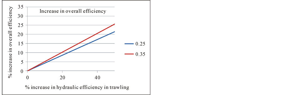
Figure 1. Efficiency increase for 0.25% and 0.35% initial trawling ess.
screw. Analysis show, that the pitch has to be increased until we have  then TM = TMD and the trawling capacity of the ship is unchanged. Further analysis of the energy consumption shows that.
 (6)
(6)
This tells us that a = 1.2 will increase the efficiency in trawling by approximately 10% and from Figure 1 it is seen to increase the overall efficiency by 5%. Also a = 1.4 will increase the efficiency in trawling by 18% and overall efficiency by 9%.
From general theory it is known that a draft tube may not have larger linear rate of increase than approximately 1:10 in order to prevent boundary layer separation and loss of effect. This means that a draft tube with Length L = D (D is the propeller diameter) will achieve 20% increase or a = 1.2 but L = 2D will achieve 40% increase or a = 1.4.
To build a draft tube behind the nozzle that can be “stowed away” is a practical problem and there is no one solution for all ships. This is however possible to achieve when 20% - 40% increase is the target. The 20% increase is no more than to change the form of the jet from circular to quadratic in a tube about 3.7 m long. The tube has to be in two parts that can be moved to each side on hinges or simply lifted up out of the water. The greatest practical problem will probably be the rudder.
6. Technical Investigations
The methodology used in the paper is simple and foundational. A more accurate model to study the problem in a technical investigation phase, is needed for each individual ship.
To achieve these efficiency increases in an economical manner one has to proceed according to the practices of professional marine design. The use of stow able draft tubes in trawlers is new and no previous experience is available. But the method is possible due to the already good experience in using propeller nozzles and variable pitch screws.
The tools available to the marine engineer in achieving successful results are mainly two, computational fluid dynamic (CFD) modeling and laboratory scale models. The CFD modelling of draft tubes is widely by both methods used by the hydropower industry [8] .
In this discussion it must be noted that even though the examples presented here cover a great part of modern trawlers, hydrodynamic models must be used in the design process in order to find the exact figure for expected fuel savings of the actual ship.
7. Conclusions
The fuel cost of the world’s fishing fleet is a problem that attracts wide attention. In all the discussion about this, there is no mention of the two-speed problem. That is the fact that towing and sailing are on two very different sailing speeds and this fact that we have called the two-speed problem, reduces the overall hydrodynamic efficiency of the vessel.
It is very likely that a trawler is running on an overall hydrodynamic efficiency of the propulsion system as low as 61% of an ordinary ship. This is because the optimal propeller diameter in trawling is much larger than the optimum propeller diameter in sailing.
A draft tube, or a diffuser, that increases the effective area of the propeller slip stream has the same hydrodynamic effect as a larger propeller. Fitting such a draft tube behind the propeller nozzle would increase the hydrodynamic efficiency considerably.
Draft tubes of the same length as the propeller diameter can result in 5% fuel savings; draft tubes of twice the length as the propeller diameter can result in 9% fuel savings.
The practical problem of the draft tube is that it has to be stowed away during sailing. The structural problems involved in constructing that mechanism are not a part of the hydrodynamic problem and are not discussed here.
Acknowledgements
The initiation of this work is a thesis in the Marine Engineering School of the Technical College in Reykjavik, [9] . The authors would like to thank the teachers and the staff for their invaluable support.
References
- Jonsdottir, H., Sparf, A.M. and Hanssen, O.J. (2005) Enviromental Benchmarking. Nordic Innovation Centre, Oslo. www.nordicinnovation.net
- Messina, G. (2006) Some Technological Contributions to Fuel Savings in Trawlers. Conference on Energy Efficiency in Fisheries Séminaire sur les Économies Dténergie à la Pêche, Brussels, 11-12 May 2006, 56. http://energyefficiency-fisheries.jrc.ec.europa.eu/c/document_library/get_file?uuid=c6537a86-e93d-4c56-9f18-c2768cf8f928&groupId=12762
- Parente, J., Fonseca, P., Henriques, V. and Campos, A. (2008) Strategies for Improving Fuel Efficiency in the Portuguese Trawl Fishery. Fisheries Research, 93, 117-124. http://dx.doi.org/10.1016/j.fishres.2008.03.001
- Messina, G. and Notti, E. (2007) Energy Saving in Trawlers: Practical and Theoretical Approaches. Proceedings of the International Conference on Marine Research and Transportation (ICMRT), Ischia, 28-30.
- Vincent, B. and Roullot, J. (2006) Towed Gear Optimisation, Application to Trawls. Conference on Energy Efficiency in Fisheries Séminaire sur les Économies Dténergie À la Pêche, Brussels, 11-12 May 2006, 40.
- Sterling, D. and Klaka, K. (2006) Energy Efficient Fishing: A 2006 Review. Part B Hull Characteristics and Efficiency. Australian Government, Fisheries Research and Development Corporation, Final Report: Part B.
- Kristensen, H.O. and Lützen, M. (2012) Prediction of Resistance and Propulsion Power of Ships. Clean Shipping Currents, 1, 6.
- Andersson, U. (2000) An Experimental Study of the Flow in a Sharp-Heel Draft Tube. Avdelningen för Strömningslära Institutionen för Maskinteknik. Licentiate Thesis, Technical Universiy of Luleå, Luleå.
- Elíasson, H.S. and Egilsson, J.S. (2014) Hydraulic Model (Straumlíkan) Dissertation Submitted for the Partial Fulfillment for the Degree of Engineer; Technical College, School of Marine Engineering, Reykjavík.