Open Journal of Applied Sciences
Vol.3 No.1(2013), Article ID:29420,4 pages DOI:10.4236/ojapps.2013.31005
3D DSMC Simulation of Rarefied Gas Flows around a Space Crew Capsule Using OpenFOAM
1Institute of High Performance Computing, A*STAR, Singapore City, Singapore
2School of Aerospace Engineering and Applied Mechanics, Tongji University, Shanghai, China
Email: shangz@ihpc.a-star.edu.sg, shangzhi@tsinghua.org.cn, schen_tju@mail.tongji.edu.cn
Received November 26, 2012; revised December 28, 2012; accepted January 5, 2013
Keywords: DSMC; Rarefied Gas; Crew Capsule; Reentry; OpenFOAM
ABSTRACT
An open source Direct Simulation Monte Carlo (DSMC) code, called as dsmcFoam in OpenFOAM, is used to study a blunt body with the shape of a space crew capsule return vehicle. The rarefied gas has the Knudsen number with 0.03. The flow with a Mach number 4.35 over the capsule was simulated by DSMC. The distributions of velocity field and temperature around the capsule were calculated. This study may provide some useful information for the reentry of the return vehicle.
1. Introduction
When the blunt body space capsules turn back to the Earth, the reentry process will undergo the process from rarefied to continuum regimes. The atmosphere is rarefied gas when the altitude is above 80 km from the sea level on the Earth.
Normally, Knudsen number, defined in Equation (1), is employed to describe the degree of gas rarefaction.
 (1)
(1)
where  is the mean free path of the gas molecules; L is the characteristic dimension of the flow.
A rarefied gas may be divided into several different flow regimes according to its level of rarefaction as quantified by Kn. When Kn is greater than 0.01, the gas is sufficiently rarefied. When Kn is greater than 10, free molecule flow occurs [1,2].
In fluid flows, when the continuum fluid approximation is contented, Navier-Stokes CFD methods [3-5] can be employed to performance the simulations. However, when the continuum fluid approximation is broken down, the constitutive equations that describe the relationships of shear stress and heat transfer with other variables are untenable. Furthermore, the linear transport terms of mass, diffusion, viscosity and thermal conductivity in the differential equations are no longer valid [1]. Typically, the Boltzmann equation of kinetic theory is the governing equation for such flows [1]. A common example of flow regime, where the Boltzmann equation would be necessary, is the operation of flight vehicles in the upper atmosphere. Many methods, such as analytical solutions, the finite pointset method and Boltzmann CFD etc. [1], can be used to solve the Boltzmann equation. However, they are either complicated or time-consuming. The direct simulation Monte Carlo (DSMC) method, which is regarded as a numerical method for solving the Boltzmann equation, is therefore developed.
The basis of the DSMC method, first formulated by Bird, is to numerically solve the Boltzmann equation. Since Graeme Bird in 1961 [6] introduced the direct simulation Monte Carlo (DSMC) method, this method has been used to solve many engineering problems from planetary spacecraft reentry [3,7,8] to micro-scale rarefied gas flows [4,5,9].
In this paper, the DSMC, which is based on OpenFOAM, is used to do the studied of a blunt body with the shape of a capsule crew return vehicle. The simulation is under supersonic conditions with a Mach number 4.35.
2. Direct Simulation Monte Carlo Method
Direct Simulation Monte Carlo (DSMC) is a physical simulation method to solve the Boltzmann equation. During the simulation, Monte Carlo method is used to represent molecular collisions and statistics of the random samples [3-9].
In Boltzmann equation, the number of molecules, dN, will be determined by the phase space of the system, which is the function of position r (x, y, z coordinate) and velocity  along the x, y, z coordinate respectively.
 (2)
(2)
Normally Boltzmann equation is a traditional mathematical option for analyzing gas flows in microscopic level. In classical mechanics the entire flow can be successfully described in terms of position, velocity and internal state of each and every molecule at a particular instant. It can be described as the following equation [6].
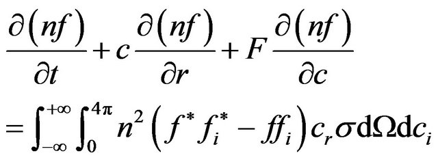 (3)
(3)
where n is number density defined as , f is velocity distribution function, c is velocity,
  is post collision velocity distribution function. ci and fi is velocity and velocity distribution function of another molecules, cr is relative velocity and
  is the differential of collision cross section.
From Boltzmann Equation (3), it can be seen that to solve Boltzmann equation is not easy. The right hand side of Equation (3) is a form of integral-differential and seven variables needs to be solved simultaneously [6]. Another way to model the collision and inverse collision terms is difficult either [3,6].
However following the advantages of computer technology, the molecular models can be employed do the direct numerical simulation (DNS) directly from the physical properties of the gases. DSMC is one kind of these methods which employs probabilistic procedures for analyzing gas flows [6].
Based on the statistic analysis, a physical parameter of number density, which is called number of equivalent particles defined as the number of particles in sample space per unit volume, is introduced to represent the characters of gas particles in real space through a single particle in sample space. Based on the statistic analysis, an assumption can be made that, in this sample space, initially the particles are distributed randomly. Therefore it can be deduced that Boltzmann equation will have only one dependent variable that is the particle distribution function. The remaining task is to solve the collision term. Collisions can be solved through a probability basis of collision between two particles proportioned by the product of cr and σ [3,6].
Due to the average value of the probability should be calculated for each cell, the cells or grids have to be used in the sample space to perform DSMC [3-9]. It is the reason why DSMC will mesh the simulation domain.
3. Code Description
The DSMC code in OpenFOAM version 1.7.1 [10] is used in this paper for the studies. The solver named as dsmcFoam is developed in OpenFOAM to perform the direct simulation Monte Carlo [11]. It is based on Bird’s original formulation [12].
The dsmcFoam solver can deal with the steady and transient simulations with 2D and 3D geometries. The variable hard sphere (VHS) collision model and LarsenBorgnakke internal energy redistribution model [7] are used to perform the collision process of the molecules. The free-stream flow boundary conditions can be set at inlet and outlet boundaries. The diffuse wall reflection boundaries are used for the solid walls [10].
When the simulations are starting, dsmcInitialise is firstly called to create initial configurations of DSMC particles in the flow regions. This initialization can be run as a parallel pre-processing. It is very useful for the simulations on the arbitrary geometries. After the initialization, dsmcFoam, the DSMC solver, is employed to do the calculations. If the initialization is performed as the parallel, the solver must be carried out with the parallel running. When the calculation is finished, the flow fields of velocities and the distributions of temperature are post-processed automatically for a serial running. If the computing is parallel, a reconstructPar command should be called to collect the results among the processors. The dsmcFieldsCalc can be called to calculate the intensive fields (density, velocity and temperature) from extensive fields (mass, momentum and energy) from the collected results.
Several benchmark validation cases, including 1D relaxation to equilibrium, 2D and 3D hypersonic flows, were studies by Scanlon etc. [11]. It is confirmed the DSMC code in OpenFOAM is able to do the simulations of rarefied gas flows. In this paper, the application using dsmcFoam solver is extended to the practical blunt body space capsule.
4. Applications
The geometry model of the blunt body space capsule is used same as the Crew Exploration Vehicle (CEV) [13]. Figure 1 shows the geometry of the vehicle. This vehicle has a spherical segment heat shield that is jointed by a small toroidal section to a truncated cone shaped crew compartment.
The hexahedral mesh is generated around the space capsule. The total mesh cells are 80,000. Figure 2 shows the mesh generation around the space capsule.
The case considers the flow as a mixture of Oxygen and Nitrogen at a total number density of 1 × 10²⁰ atoms/m3. The Mole fractions are of Oxygen 0.223 and Nitrogen 0.777 respectively. The flow has a temperature of 143.3 K at a velocity of 1191.9 m/s over the spherical segment heat shield. The situation can be used to mimic the reentry of the return vehicle from out space.
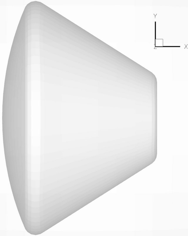
Figure 1. Geometry of space capsule.
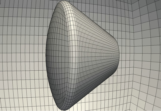
Figure 2. Hexahedral mesh around space capsule.
The radius of the shield is 0.2 m so that the Knudsen number based on the diameter of the spherical segment heat shield is 0.03,061. The Mach number of the flow is 4.35 and the surface temperature of the space capsule is 550 K. The Reynolds number of the flow is 165.62. The time-step was fixed as 1.0 × 10⁻⁶ s. The steady-state can be reached after 72 hours running in parallel with 4 processors (Intel 2.83 GHz).
Figure 3 shows the velocity vector fields around the space capsule. It can be seen that the maximum velocity is above 1200 m/s. It means the velocity is accelerated when the fluid flows over the space capsule. Therefore the maximum Mach number should be increased larger than the initial value 4.35.
Figure 4 shows the distributions of Mach number around the space capsule. It can be seen that the maximum Mach number locates at the front of the shield of the space capsule with a short distance from the wall outside the region of the low Mach number. The lower Mach number locates at the regions near the both ends of the space capsule.
Figure 5 shows the temperature distributions. It can be seen that the higher temperature locates at the front of the shield of the space capsule. The maximum temperature has a short distance from the wall of the shield. It reaches 895 K high. The temperature at the wall of the shield is about 700 K. It is higher than the initial wall temperature (550 K). At the region near the back toroidal section, the temperature is about 600 K. It could be induced when the fluid flows over the space capsule, the flow shrinks to the back region following the flow path shown in Figure 3 and the low velocity, shown in Figure 4, is difficult to remove the hot fluid coming from the front region away. The heat is accumulated; therefore, the temperature increases and finally reaches a balance.
5. Conclusions
From the results, it can be seen that when the rarefied gas

Figure 3. Velocity vector fields (m/s).

Figure 4. Distributions of Mach number.
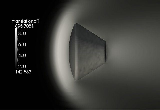
Figure 5. Distributions of temperature (K).
flows over the space capsule, the flow fields will affect the temperature distributions. The high temperature region locates at the area of low Mach numbers, i.e. these two regions are overlapped.
From the simulations, it can be seen dsmcFoam code is able to simulate the complex 3D rarefied gas flows. In the future, more complex situations, such as different angles of attack, the effects of different Knudsen numbers and the chemical reaction for hypersonic flows, will be considered.
6. Acknowledgements
Supports provided by the National Natural Science Foundation of China under Grant No. 51276130, by the fundamental Research Funds for the central Universities (2012) and by the Ph.D. Programs Foundation of Ministry of Education of China (No. 20120072110037) are gratefully acknowledged.
REFERENCES
- P. S. Prasanth and J. K. Kakkassery, “Direct Simulation Monte Carlo (DSMC): A Numerical Method for Transition-Regime Flows—A Review,” Journal of Indian Institute of Science, Vol. 86, 2006, pp. 169-192.
- M. Rapp, J. Gumbel and F. J. Lubken, “Absolute Density Measurements in the Middle Atmosphere,” Annales Geophysicae, Vol. 19, No. 5, 2001, pp. 571-580. doi:10.5194/angeo-19-571-2001
- I. D. Boyd, “Direct Simulation Monte Carlo for Atmospheric Entry. 2: Code Development and Application Results,” Notes for VKI Shortcourse, Nonequilibrium Gas Dynamics: From Physical Models to Hypersonic Flights, 2008.
- G. A. Bird, “Monte Carlo Simulation in an Engineering Context,” Progress in Astronautics and Aeronautics, AIAA, New York, Vol. 74, No. 1, 1981, pp. 239-255.
- H. Xue and S. Chen, “DSMC Simulation of Microscale Backward-Facing Step Flow,” Nanoscale and Microscale Thermalphysical Engineering, Vol. 7, No. 1, 2003, pp. 69-86. doi:10.1080/10893950390150449
- G. A. Bird, “Approach to Translational Equilibrium in a Rigid Sphere Gas,” Physics of Fluids, Vol. 6, No. 10, 1963, pp. 1518-1519. doi:10.1063/1.1710976
- G. A. Bird, “Molecular Gas Dynamics and the Direct Simulation of Gas Flows,” Clarendon, Oxford, 1994.
- J. Fan, I. D. Boyd, C. P. Cai, K. Hennighausen and G. V. Candler, “Computation of Rarefied Flows around a NACA0012 Airfoil,” AIAA Journal, Vol. 39, No. 4, 2001, pp. 618-625. doi:10.2514/3.14778
- Y. Zhang and Y. Meng, “Study on Micro-Scale Gas Slider Bearing with Direct Simulation Monte Carlo Method,” Advanced Tribology, Vol. 3, 2010, pp. 544-545.
- “OpenFOAM version 1.7.1,” OpenCFD Ltd., 2010.
- T. J. Scanlon, E. Roohi, C. White, M. Darbandi M and J. M. Reese, “An Open Source Parallel DSMc code for rarefied gas flows in Arbitrary Geometries,” Computers & Fluids, Vol. 39, No. 10, 2010, pp. 2078-2089. doi:10.1016/j.compfluid.2010.07.014
- G. A. Bird, “Monte Carlo Simulation of Gas Flows,” Annual Review of Fluid Mechanics, Vol. 10, 1978, pp. 11-31. doi:10.1146/annurev.fl.10.010178.000303
- B. R. Hollis, “Blunt-body Entry Vehicle Aerothermodynamics: Transition and Turbulence on the CEV and MSL Configurations,” 40th Fluid Dynamics Conference and Exhibit, Chicago, 28 June-1 July 2010, pp. 2010-4984.