Modeling and Numerical Simulation of Material Science
Vol.4 No.1(2014), Article ID:41928,7 pages DOI:10.4236/mnsms.2014.41005
Finite Element Method Investigation of the Effect of Cold Expansion Process on Fatigue Crack Growth in 6082 Aluminum Alloy
1Laboratoire LPQ3M, Université de Mascara, Mascara, Algeria
2Département de Génie Mécanique, University of Sidi Bel Abess, Sidi Bel Abess, AlgeriaEmail: *aid_abdelkrim@yahoo.com
Copyright © 2014 Abdelkrim Aid et al. This is an open access article distributed under the Creative Commons Attribution License, which permits unrestricted use, distribution, and reproduction in any medium, provided the original work is properly cited. In accordance of the Creative Commons Attribution License all Copyrights © 2014 are reserved for SCIRP and the owner of the intellectual property Abdelkrim Aid et al. All Copyright © 2014 are guarded by law and by SCIRP as a guardian.
Received July 25, 2013; revised August 27, 2013; accepted September 3, 2013
Keywords:Crack Growth; Cold Expansion Hole; Residual Stress; Fatigue Life
ABSTRACT
Cold expansion is an efficient way to improve the fatigue life of an open hole. In this paper, three finite element models have been established to crack growth from an expanded hole which is simulated. Expansion and its degree influence are studied using a numerical analysis. Stress intensity factors are determined and used to evaluate the fatigue life. The residual stress field is evaluated using a nonlinear analysis and superposed with the applied stress field in order to estimate fatigue crack growth. Experimental test is conducted under constant loading. The results of this investigation indicate that expansion and its degree are a benefit of fatigue life and a good agreement was observed between FEM simulations and experimental results.
1. Introduction
The fatigue life improvement of cold expanded fasten holes is attributed to the presence of compressive residual stress induced by cold expansion. The fatigue fracture of fastener holes accounts for 50% - 90% of structural fracture of aircrafts.
Over the last 40 years, because of its simple realization and remarkable enhancement of the fatigue life of holes (usually 3 - 5 times than that of holes without cold expansion), the cold expansion process has been widely used to improve the fatigue life of components with fastener holes [1].
The cold-expansion, which is developed by the Fatigue Technology Inc. (FTI, 1994), is obtained by using increased pressure to plasticize an annular zone around the hole. The pressure on the surrounding material is realized by interference generated between the drilled plate and the pressuring element, i.e. the mandrel. When the mandrel is removed and the superficial pressure on the hole is erased, a residual stress field is created due to the action of the elastic deformed material on that under plastic condition [2].
Cold expansion can be achieved in several different ways. A common feature of most methods is to insert an oversized object from one side of the holed plate and remove it from the other side. The main differences in methods relate to the shape of the oversized object and whether a sleeve is used in the hole during cold expansion [2-12]. Compressive residual stress around a hole is very beneficial at resisting fatigue because it reduces the resultant stress at the critical edge of the hole location when the plate undergoes a tensile load [13]. In this paper, the results involve the first part, on experimental analysis to investigate the effect of cold expansion on fatigue crack growth in aluminium alloy. Numerical studies were carried out in order to identify the fields of compressive stress at the hole due to the cold expansion process and to valid the FEM model.
2. Experimental and Numerical Model
2.1. Experimental Procedure
The experimental part of this work is subdivided into three steps: Tension test, fatigue test and the introduction of residual stresses by cold expansion.
2.1.1. Materials and Specimens
Aluminium alloy 6082-T6 from 8.0 mm thickness was used in this investigation (Figure 1).
Tensile specimens were machined with the dimensions and geometry as specified by the ASTM B557-06 designation. The quasi-static tension test was performed with a head speed displacement of 0.02 mm∙s−1. Tensile strain of specimens was measured with an Instron® extensometer model 2620-601.
The mechanical properties and chemical compositions of this material were presented in Tables 1 and 2, respectively.
2.1.2. Fatigue Tests and Cold Expansion
Specimens were cut from aluminum alloy plates of 8mm thick plate, with the axis parallel to the rolling direction of the plate. The SENT (Single Edge Notch Tension) specimen configuration used for the experiments is similar to the suggestion in the ASTM E647-95 [E647-95]. The dimensions of the specimen are shown in Figure 2.
A slit of 1mm in width and 15mm in length was machined on one lateral side of the specimen. A pre-crack from the slit tip was introduced by cyclic loading and the total length of the slit and the pre crack was (a0 + r where r = d/2). A hole was drilled at the pre-crack tip. The hole was firstly drilled conventionally and then carefully enlarged by a boring bar to a desired radius.
The cold working expansion process was realized by forcing a hard steel ball of 6 mm inside a predrilled hole(the initial diameters of the hole are: 5.9, 5.8 and 5.75 mm, see Figure 3).

Figure 1. Tensile specimen geometry (all dimensions in mm).
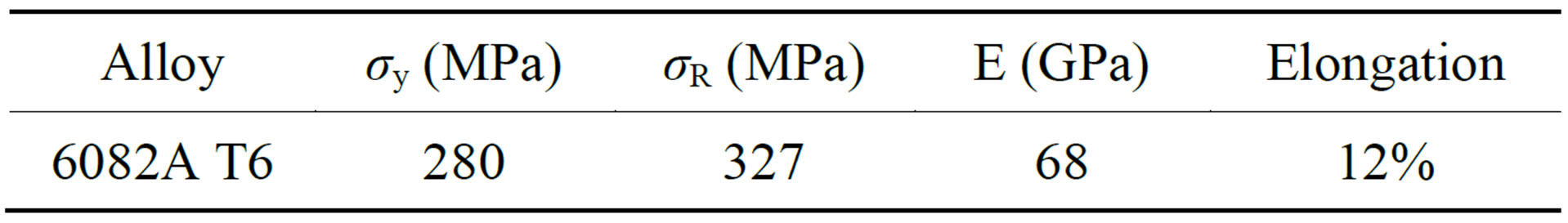
Table 1. Mechanical properties of test material.
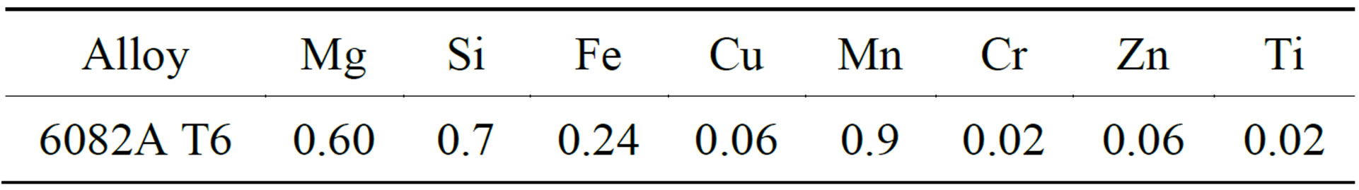
Table 2. Chemical compositions of material.
The degree of expansion is calculated as follows [14]:
 (1)
(1)
There are 3 DCE applied: 17%, 34% and 43%. Fatigue tests were conducted using a constant amplitude loading. Load ratio, 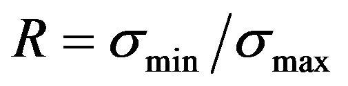 , is 0.57, where σmax and σmin are the maximal and minimal loading. Hydraulic machine INSTRON 8501 was used at a frequency of 30 Hz. During fatigue testing, a video camera with a scale of 0.1 mm was used to determine the crack initiation and propagation in the entry and exit faces of the specimen.
2.2. Finite Element Simulation
Three finite element analysis was used to simulate the
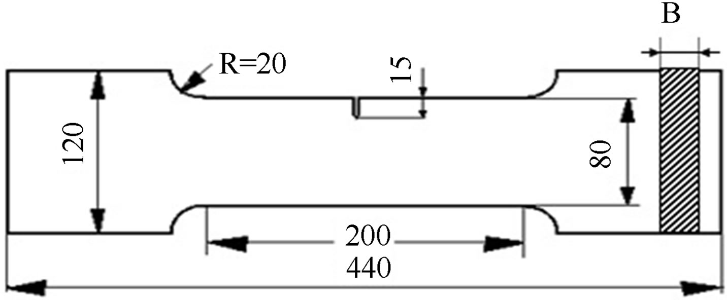
Figure 2. Fatigue specimen (SENT).
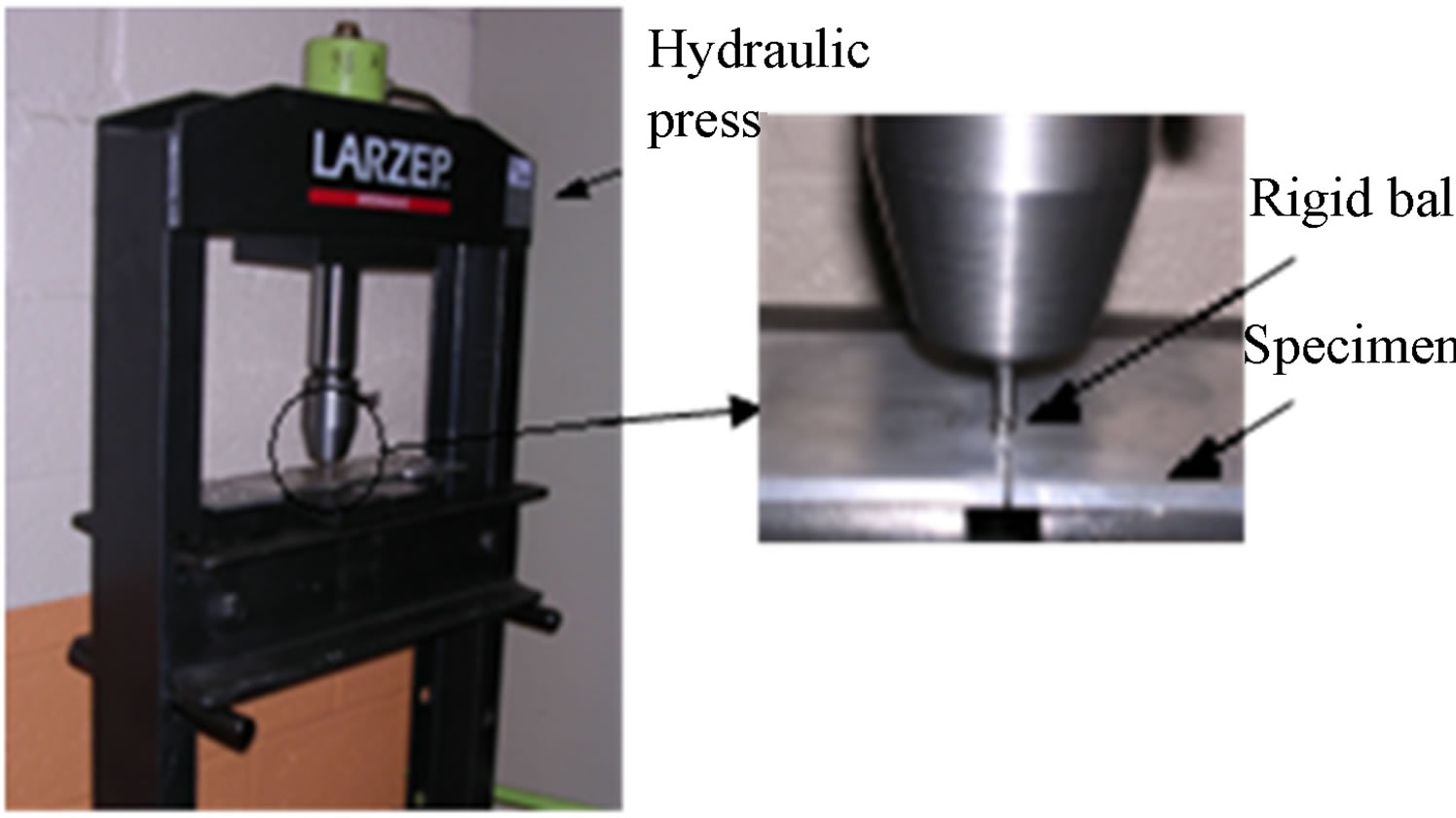
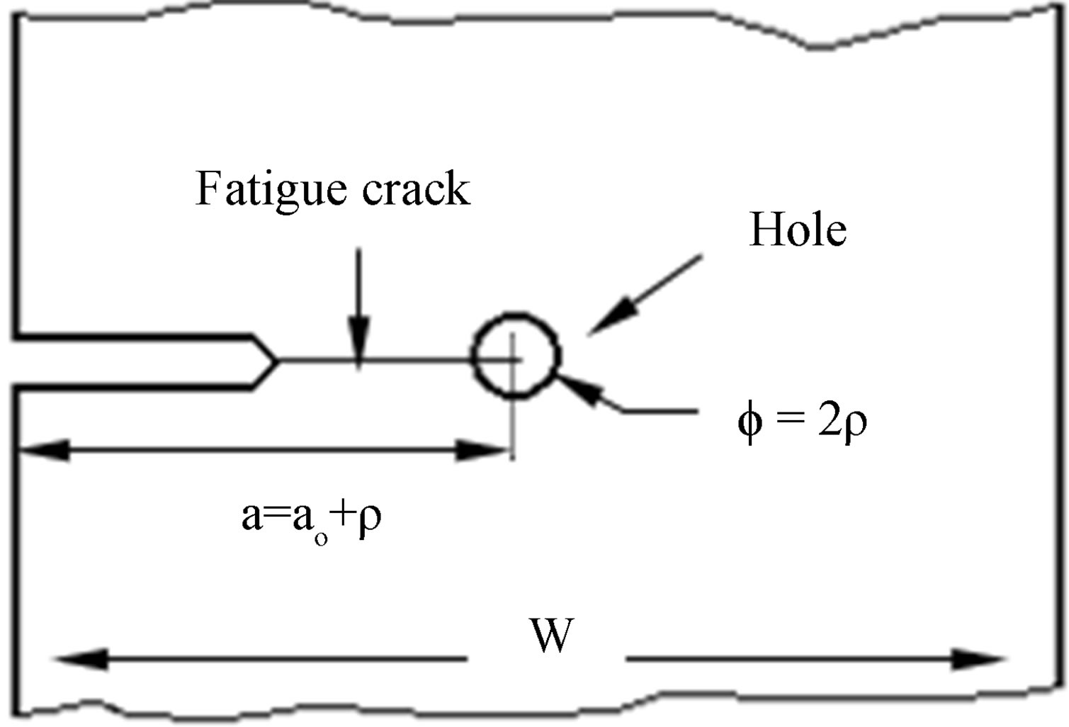
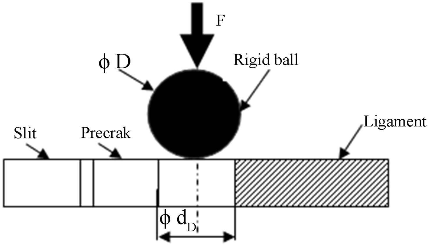
Figure 3. Cold expansion process.
crack growth in SENT specimen using the commercial code ANSYS. This computer program has the capabilities to simulate, step by step, the rigid ball displacement in the hole axis direction through the plate thickness, thus permitting to establish the variability of the stress field not only in the plane of the plate, but also through the specimen thickness. A two-step nonlinear analysis was performed, in order to simulate the effect of cold expansion of the crack growth numerically, in the first step, The simulation of cold expansion was carried out by changing the position of the rigid ball on the Z-direction, the rigid ball was pushed through the hole and removed from the other side by applying displacement increments on the top nodes of the rigid ball. This phase represents the storing of the residual stress field near the hole. After this operation, there is a relaxation of the tensile strain due to the deformability of the plate under the loading action of cold expansion, on attaining equilibrium and in the second step; this plate was subjected to remote longitudinal stresses to simulate the process of loading during the fatigue testing. Fracture mechanics aims to determine the effect of any cracks on the mechanical behavior of structures. Contributing to this field, we analyzed the influence of residual stresses induced by the cold expansion on the crack growth in 6082-T6 Aluminum alloy.
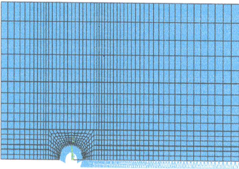
Figure 4 shows the finite element mesh. Taken into account the symmetry of loading and geometry, only the half of the model is studied in order to reduce the calculation time. Three dimensional solid elements with eight nodes were used in this work. The mesh is denser around the hole (expansion) and on the way of crack propagation. The same mesh was used to simulate expansion and propagation. An elastic-plastic material relationship was used to represent the aluminum alloy 6082A T6 behavior. The theory of incremental plasticity is introduced to modelling the material nonlinearity. The iterative method of Newton-Raphson is used as an approach to solve nonlinear equations by finite elements.
3. Description of the Procedure to Estimate the Fatigue Life
Superposition techniques are often used when assessing the effects of a known residual stress field on fatigue crack propagation. To estimate crack growth from the equation, some authors [15-18] compute a stress intensity factor which is associated with the initial pre-existing residual stress field (Kres). This factor it then superposed upon the stress intensity factor that results from external loading (Kapp) to give the total resultant stress intensity factor for the maximum and minimum loads:
 (2)
(2)
The stress intensity range is then calculated using:
 (a)
(a)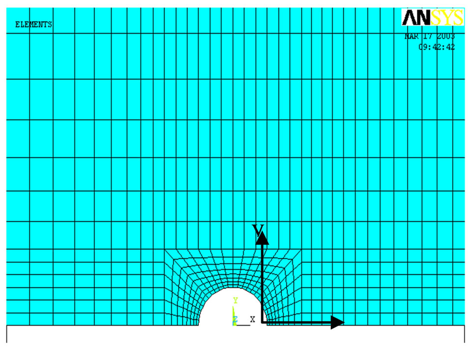 (b)
(b)
Figure 4. Finite element mesh. (a) Specimen and ball (expansion); (b) Mesh for expansion and propagation.
 (3)
(3)
According to these authors, the stress intensity range is independent on residual stresses and only stress ratio (R) is affected.
 (4)
(4)
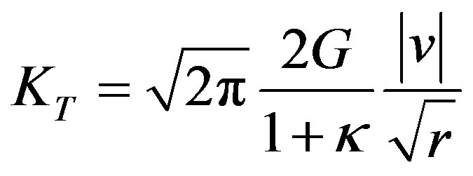
Total stress  induces a displacement of crack face. Given this displacement value and assuming the fracture mode one, ANSYS calculates the total stress intensity factor with the Irwin theory [19]:
 (5)
(5)
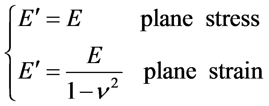
where G is shear modulus,  is equal to (3-4n) if plane strain is assumed and to
  in plane stress, n is Poisson’s ratio, v displacements in local cartesian coordinate system as shown in Figure 5.
According to the Equations (3) and (4), Stress intensity
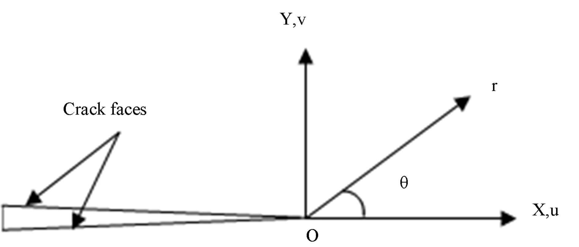
Figure 5. Crack tip Local coordinate system.
range is calculated as follows:
 (6)
(6)
 (7)
(7)
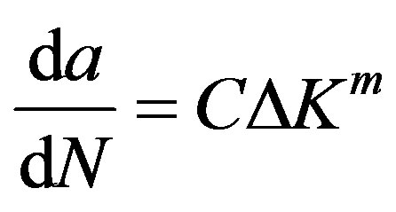
Crack growth depends also on the load ratio [20-22]. This effect is introduced by Equation (5). In our case we take a value of load ratio that minimize the effect of crack opening and allows us to use Paris law to evaluate crack growth rate.
 (8)
(8)
Many authors use the superposition technique [23,24]. This use has been criticized by some researchers because it doesn’t take in consideration residual stress relaxation during crack propagation [25-28]. In the present work, this effect won’t be taken in count.
Macro files were implemented to simulate crack propagation, using Paris law, under residual stresses influence; this is not possible to do directly in this simulation tool. Calculation procedure is represented on Figure 6.
afinal represents the final value of crack length at witch calculation will be stopped.
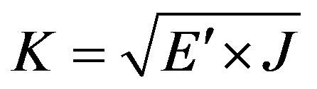
As shown in this figure, we used an Ansys command to calculate J-integral. This method has the advantage of keeping the same mesh of the specimen during crack propagation. Stress Intensity Factors, assuming fracture mode one, are calculated using the Equations (12) and (13).
 (9)
(9)
With:
 (10)
(10)
4. Results and Discussions
4.1. Validation of the Finite Element Analysis
Figure 7 compare the experimental and finite elements results in three cases of the degree of cold expansion

Figure 6. Procedure to estimate fatigue life.
(DCE): DCE = 1.7%, 3.4% and 4.3% applied to the 6 mm hole diameter.
A first observation from the reading of Figure 7 is that whatever the degree of cold expansion DCE, the crack length affects significantly on the life time N. Indeed, this life time N increases proportionally with the crack length and its variation takes an exponential evolution if the crack is higher whatever the value of DCE. According to the experimental and numerical analysis, it can be seen that the result gave a good correlation between various methods, thus establishing confidence in the results of the finite element modeling for the cold expansion process.
It is now that the cold expansion process produces a uniform negative residual stress throughout the depth of a hole.
4.2. Effect of Cold Expansion
The effect of expansion and the increase of DCE is illustrated in Figure 8.
Five degrees of expansion are applied to a hole of diameter 6 mm. DCE equal to zero correspond to a hole without expansion (fatigue plane). The initial number of cycles, corresponding to the initiation of the crack, is taken equal to 1E5 cycles. This is not true because expansion has also an effect on initiation phase, this result
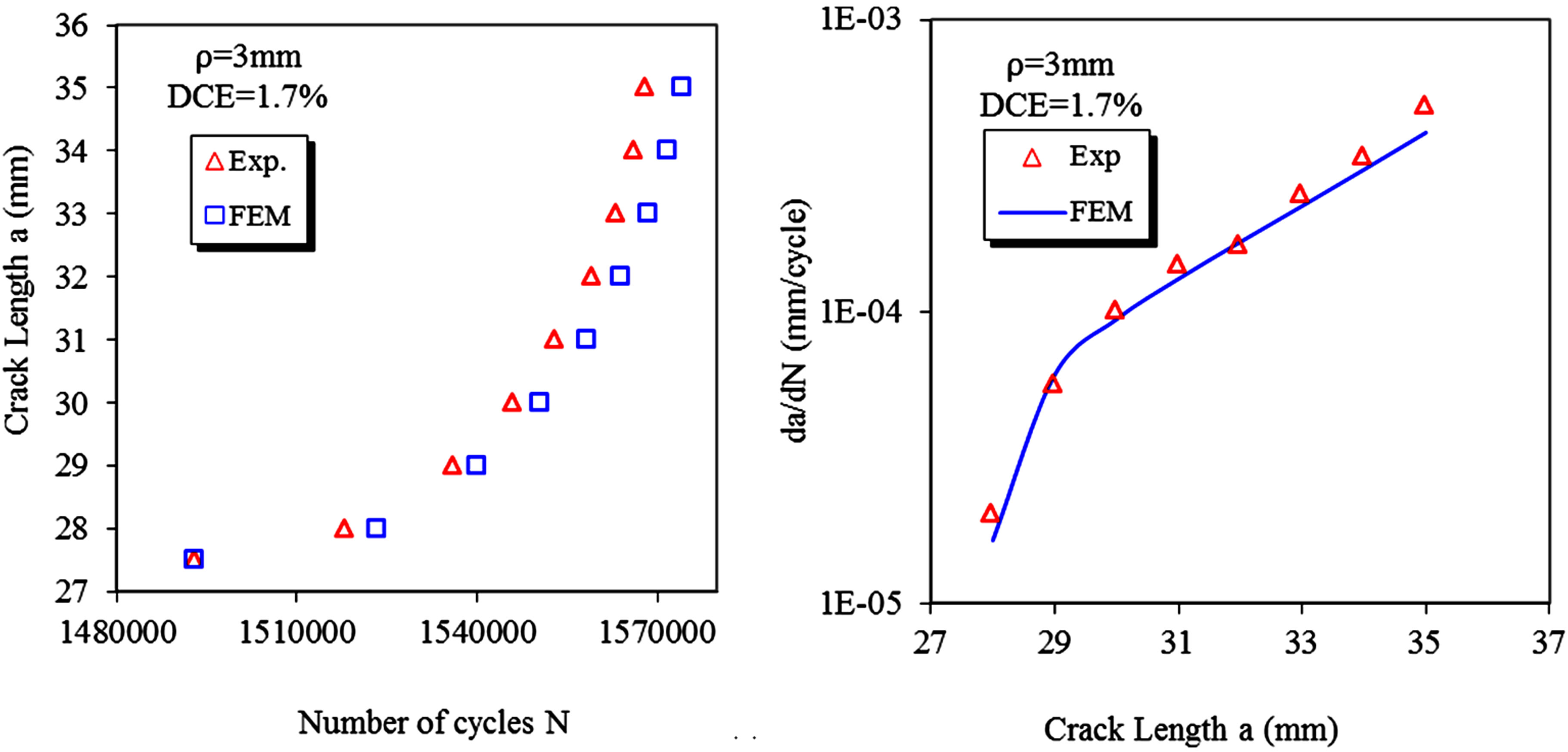
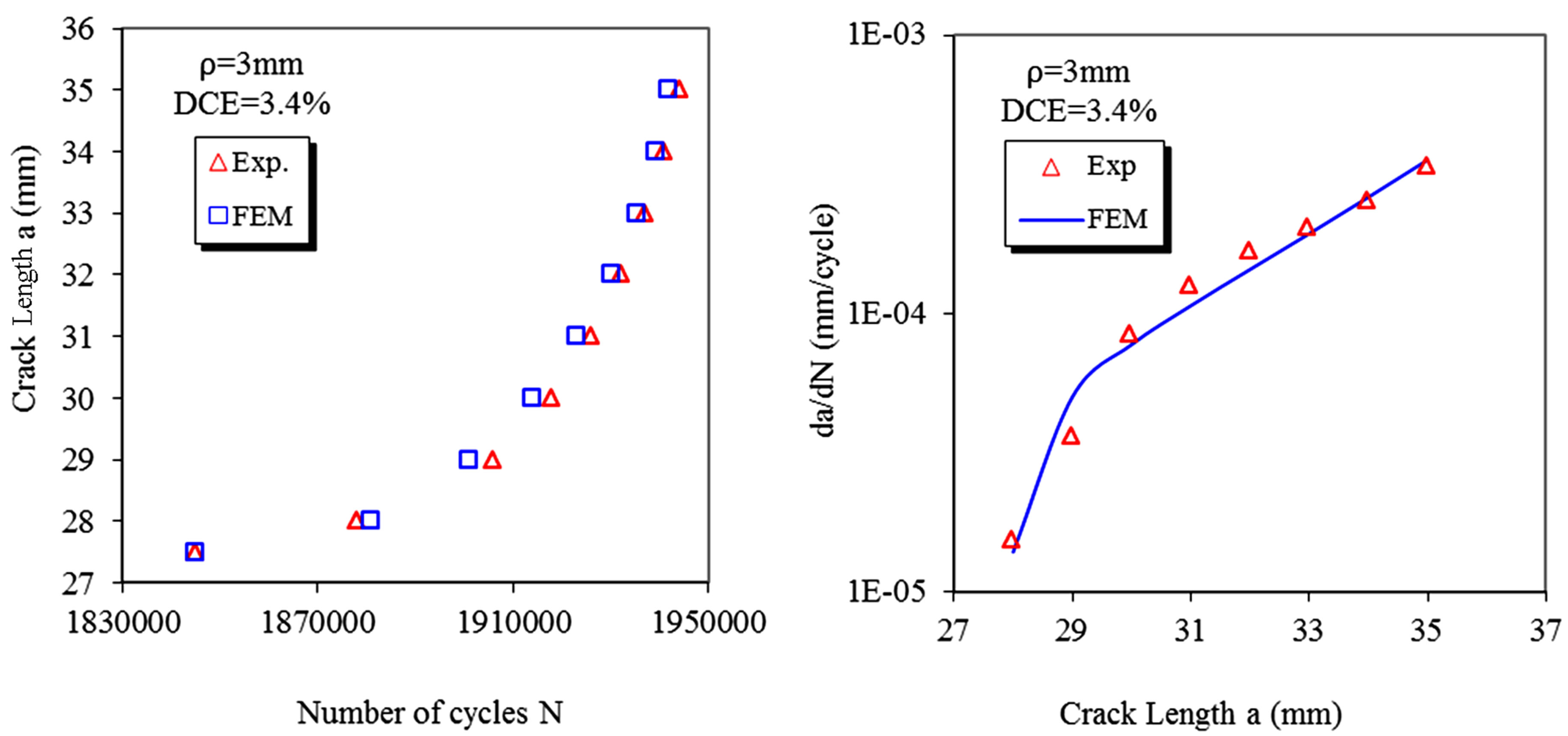
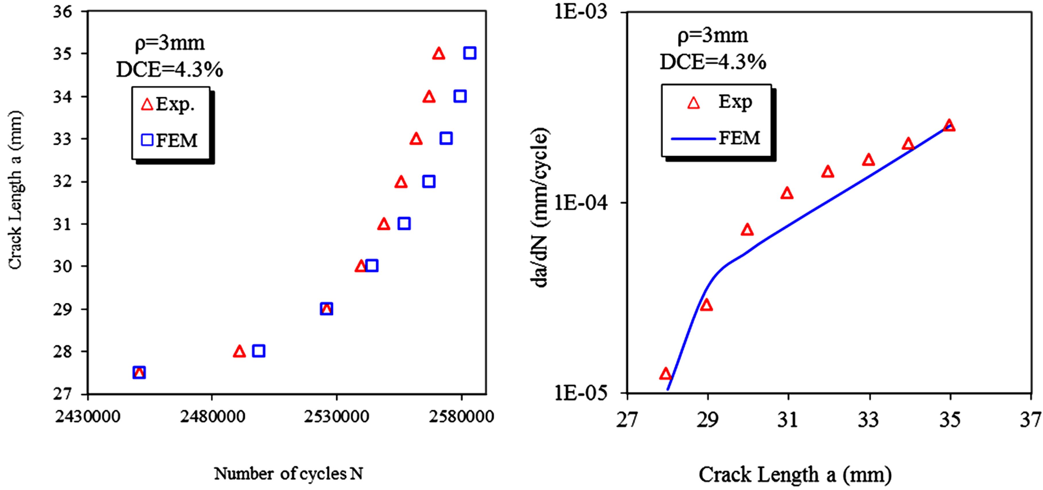
Figure 7. Comparison between experimental and finite element results.
were confirmed by other researchers [29,30].
The expansion improves fatigue life due to the existence of residual stresses on the side of the hole. This field of stresses tends to decrease the crack growth rate as shown in Figure 9.
5. Conclusions
The aim of this study is to analyze the effect. By finite element method, we investigated the effect of cold expansion process on the crack growth in aluminum alloy, from experimental and numerical results, we can deduce the following conclusions.
The ability of cold expansion to produce beneficial compressive residual stresses around fastener holes was
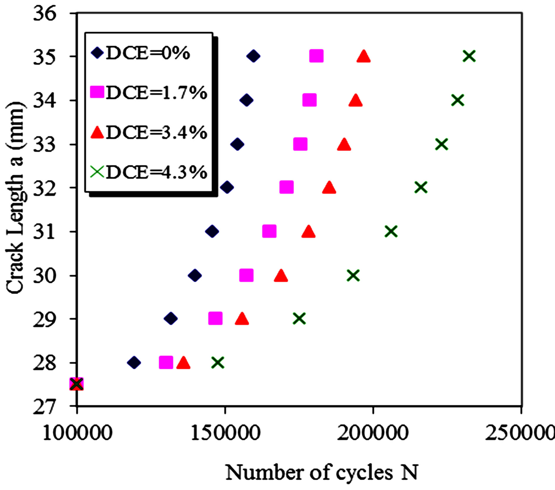
Figure 8. Improvement of fatigue life by expansion.
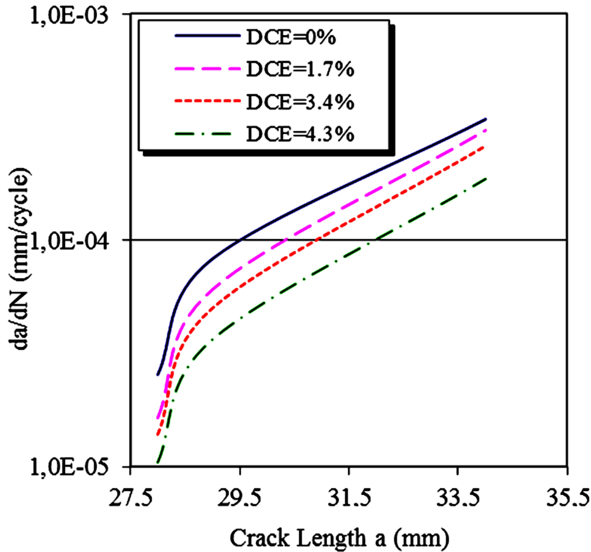
Figure 9. Effect of expansion degree on fatigue crack growth rate.
numerically investigated in this work. The stress superposition technique was applied to plot stress intensity factors by the finite element in ANSYS. This analysis tool was implemented in order to plot SIF (Stress Intensity Factors) during the crack propagation.
Expansion process was simulated with a nonlinear analysis. Residual stresses were superposed to the applied stress field and the resulting stress intensity factors were calculated for each crack length. Crack propagation phase was considered only as the linear behavior of the studied aluminum alloy.
Simulation results are in good agreement with the experiment’s data. This confrontation demonstrates the benefit that has expansion and its degree DE on crack propagation.
Other works are conducted to see the effect of residual stresses on Kmin, Kmax and ΔK separately. The redistribution of the residual stress field during the initiation and the propagation of the crack and the numerical determination of the optimal value of the expansion degree are also under study.
REFERENCES
- Y. S. Liu, X. J. Shao, J. Liu and Z. F. Yue, “Finite Element Method and Experimental Investigation on the Residual Stress Fields and Fatigue Performance of Cold Expansion Hole,” Materials and Design, Vol. 31, No. 3, 2010, pp. 1208-1215. http://dx.doi.org/10.1016/j.matdes.2009.09.031
- V. Nigrelli and S. Pasta, “Finite-Element Simulation of Residual Stress Induced by Split-Sleeve Cold-Expansion Process of Holes,” Journal of Material Processing Technology, Vol. 205, No. 1-3, 2008, pp. 290-296. http://dx.doi.org/10.1016/j.jmatprotec.2007.11.207
- A. Amrouche, G. Mesmacque, S. Garcia and A. Talha, “Cold Expansion Effect on the Initiation and the Propagation of the Fatigue Crack,” International Journal of Fatigue, Vol. 25, No. 9, 2003, pp. 949-954. http://dx.doi.org/10.1016/S0142-1123(03)00127-0
- J. Bertrand and C. Fabrice, “Prévision de la Fissuration par Fatigue en préSence de Contraintes Résiduelles,” Méc. & Industries, Vol. 6, 2005, pp. 75-88.
- D. Stefanescu, J. R. Santisteban, L. Edwards and M. E. Fitzpatrick, “Residual Stress Measurement and Fatigue Crack Growth Prediction after Cold Expansion of Cracked Fastener Holes,” Journal of Aerospace Engineering, Vol. 17, No. 91, 2004, pp. 893-1321.
- M. Toparli and T. Aksoy, “Effect of the Residual Stresses on the Fatigue Crack Growth Behaviour at Fastener Holes,” Materials Science and Engineering A, Vol. 225, No. 1-2, 1997, pp. 196-203. http://dx.doi.org/10.1016/S0921-5093(96)10875-3
- S. Pasta, “Fatigue Crack Propagation from a Cold-Worked Hole,” Engineering Fracture Mechanics, Vol. 74, No. 9, 2007, pp. 1525-1538. http://dx.doi.org/10.1016/j.engfracmech.2006.08.006
- X. Zhang and Z. Wang, “Fatigue Life Improvement in Fatigue-Aged Fastener Holes Using the Cold Expansion Technique,” International Journal of Fatigue, Vol. 25, No. 9-10, 2003, pp. 1249-1257. http://dx.doi.org/10.1016/S0142-1123(03)00152-X
- X. Zhang and Z. Wang, “Predicting Fatigue Crack Growth Life for Cold-Worked Holes Based on Existing ClosedForm Residual Stress Models,” International Journal of Fatigue, Vol. 25, No. 9, 2003, pp. 1285-1291. http://dx.doi.org/10.1016/S0142-1123(03)00153-1
- V. D. Lacarac, D. J. Smith and M. J. Pavier, “The Effect of Cold Expansion on Fatigue Crack Growth from Open Holes at Room and High Temperature,” International Journal of Fatigue, Vol. 23, No. 1, 2001, pp. 161-170. http://dx.doi.org/10.1016/S0142-1123(01)00125-6
- H. D. Gopalakrishna, M. H. N. Narasimha, M. Krishna, M. S. Vinod and A. V. Suresh, “Cold Expansion of Holes and Resulting Fatigue Life Enhancement and Residual Stresses in Al2024T3 Alloy—An Experimental Study,” Engineering Failure Analysis, Vol. 17, No. 2, 2010, pp. 361-368. http://dx.doi.org/10.1016/j.engfailanal.2009.08.002
- P. F. P de Matos, P. M. G. P. Moreira, I. Nedbal and P. M. S. T. de Castro, “Reconstitution of Fatigue Crack Growth in Al-Alloy 2024-T3 Open-Hole Specimens Using Microfractographic Techniques,” Engineering Fracture Mechanics, Vol. 72, No. 14, 2005, pp. 2232-2246. http://dx.doi.org/10.1016/j.engfracmech.2005.02.005
- T. N. Chakherlou and J. Vogwell, “The Effect of Cold Expansion on Improving the Fatigue Life of Fastener Holes,” Engineering Failure Analysis, Vol. 10, No. 1, 2003, pp. 13-24. http://dx.doi.org/10.1016/S1350-6307(02)00028-6
- A. Amrouchea, M. Su, A. Aid and G. Mesmacque, “Numerical Study of the Optimum Degree of Cold Expansion: Application for the Pre-Cracked Specimen with the Expanded Hole at the Crack Tip,” Journal of Materials Processing Technology, Vol. 197, No. 1-3, 2008, pp. 250- 254.
- D. L. Rich and L. F. Impellizzeri, “Fatigue Analysis of Cold-Worked and Interference Fit Fastener Holes. Cyclic Stress-Strain and Plastic Deformation Aspect of Fatigue Crack Growth,” ASTM STP 637 Amer. Soc. for Test and Mat, 1977, pp. 153-175.
- J. E. LaRue, “The Influence of Residual Stress on Fatigue Crack Growth,” Master Thesis, Mississippi State University, Starkville, 2005.
- M. Chobin, M. Anggit, K. Kazuo, I. Yoshiki and S. Akihide, “Crack Growth Arrest by Redirecting Crack Growth by Drilling Stop Holes and Inserting Pins into Them,” Engineering Failure Analysis, Vol. 16, No. 1, 2009, pp. 475-483. http://dx.doi.org/10.1016/j.engfailanal.2008.06.009
- J. E. LaRue and S. R. Daniewicz. “Predicting the Effect of Residual Stress on Fatigue Crack Growth,” International Journal of Fatigue, Vol. 29, No. 3, 2007, pp. 508- 515. http://dx.doi.org/10.1016/j.ijfatigue.2006.05.008
- W. J. Keith and L. D. Martin, “Predicting Fatigue Crack Growth from a Pre-Yielded Hole,” International Journal of Fatigue, Vol. 31, No. 2, 2009, pp. 223-230. http://dx.doi.org/10.1016/j.ijfatigue.2008.09.007
- ANSYS User’s Manuals, Revision 11.0, 2007.
- C. S. Kusko, J. N. DuPont and A. R. Marder, “Influence of Stress Ratio on Fatigue Crack Propagation Behaviour of Stainless Steel Welds,” Welding Journal, Vol. 83, No. 2, 2004, pp. 59-64.
- D. Kujawski, “Enhanced Model of Partial Crack Closure for Correlation of R-Ratio Effects in Aluminum Alloys,” International Journal of Fatigue, Vol. 23, No. 2, 2001, pp. 95-102. http://dx.doi.org/10.1016/S0142-1123(00)00085-2
- J. A. Newman, “The Effects of Load Ratio on Threshold Fatigue Crack Growth of Aluminum Alloys,” Doctoral Thesis, Virginia University, Charlottesville, 2000.
- N. Ramesh, “Fatigue Crack Growth under Residual Stresses around Holes,” Master Thesis, Mississippi State University, Charlottesville, 2005.
- J. H. Underwood, L. P. Pook and J. K. Sharples, “Flaw Growth and Fracture,” ASTM STP 631 Amer. Soc. for Test and Mat 1977, pp. 402-4015.
- S. Fukuda and Y. Tsuruta, “An Experimental Study of Redistribution of Welding Residual Stress,” Transactions of JWRI, Vol. 7, No. 2, 1978, pp. 67-72.
- N. Chandawanich and W. N. Sharpe Jr., “An Experimental Study of Fatigue Crack Initiation and Growth from Cold Worked Holes,” Engineering Fracture Mechanics, Vol. 11, No. 4, 1979, pp. 609-620. http://dx.doi.org/10.1016/0013-7944(79)90122-X
- Y. C. Lam and K. S. Lian, “Effect of Residual Stress and Its Redistribution on Fatigue Crack Growth,” Theoretical and Applied Fracture Mechanics, Vol. 12, No. 1, 1989, pp. 59-66. http://dx.doi.org/10.1016/0167-8442(89)90015-3
- A. Todoroki and H. Kobayashi, “Prediction of Fatigue Crack Growth Rate in Residual Stress Fields,” Key Engng Mat. Fract Strength, Vol. 367, 1991, pp. 51-52.
- S. Man, “Etude de l’Influence et de l’Optimisation du Degré d’Expansion à Froid dans les Mécanismes de Réamorçage d’Une Fissure: Etude Numerique et Expérimentale,” Doctoral Thesis, Université des Sciences et Technologies de Lille, Lille, 2005.
NOTES
*Corresponding author.