American Journal of Industrial and Business Management
Vol.06 No.09(2016), Article ID:70883,26 pages
10.4236/ajibm.2016.69094
The Application of Reliability Methods for Aircraft Design Project Management
Darli Rodrigues Vieira1*, Mohamed-Larbi Rebaiaia2, Milena Chang Chain3
1Management of Aeronautical Projects, University of Quebec at Trois-Rivières, Trois-Rivières, Canada
2Mechanical Engineering Department, Laval University, Pavillon Adrien-Pouliot, Canada
3University of Quebec at Trois-Rivières, Trois-Rivières, Canada

Copyright © 2016 by authors and Scientific Research Publishing Inc.
This work is licensed under the Creative Commons Attribution International License (CC BY 4.0).
http://creativecommons.org/licenses/by/4.0/


Received: August 20, 2016; Accepted: September 24, 2016; Published: September 27, 2016
ABSTRACT
In aircraft project management, reliability and maintainability are fundamental for ensuring system safety, for optimizing the manufacturing process and for improving assembly/disassembly operations when maintenance actions are required. The inclusion of such requirements helps to minimize life cycle costs, augments the residual lifetime of aircraft and consequently increases customer satisfaction. While most papers published in the aircraft engineering literature are rather evasive or do not accurately describe the role of reliability and maintainability (RM) methods in early design phases, this paper elucidates the problem. This paper discusses various concepts such as design for reliability and risk assessment analysis for improving aircraft safety and reliability at the deployment stages. The article also focuses on how reliability prediction issues are addressed using various methods, tools and standards, such as failure modes and effect analysis, fault tree analysis and guidelines such as MIL-STD-217f and ARP4754. Finally, this paper demonstrates that reliability is crucial to consider in all phases of the life cycle of an aircraft.
Keywords:
Aircraft Engineering, Project Management, System Safety, Reliability, Maintainability

1. Introduction
The airline industry continues to grow and thrive, with a forecasted 3.3 billion passengers traveling in 2014 [1] . The strong surge in demand for new aircraft due to the growth of passenger transport worldwide, estimated at an annual rate of 5.1% over the long term, is such that, by 2030, the fleet will increase significantly. It was estimated in 2001 that the aviation industry would deliver five new aircraft per day, or 33,500 new civil aircraft over 20 years. A total of 80% of these aircraft are being or will be manufactured by the two giants of aeronautics: Airbus and Boeing. Aircraft manufacturers have order books that represent several years of production. Asia, the Middle East and Latin America are the principal costumers; they continue to show strong growth [1] - [3] . The latest data published by Boeing estimate the number of aircraft in service for the year 2014 as 21,600 aircraft and as 43,560 aircraft by 2034, as well as a demand of 38,050 aircraft with a value of $5570 billion in 2015 [3] .
One of the major challenges facing the aviation industry consists of reducing the design and production cycle time of an aircraft to the greatest extent possible with respect to three important aspects: speed of delivery to customers, quality and safety, and costs [4] - [7] .
To satisfy their requirement to deliver aircraft at specified contractual times, Airbus and Boeing rely on multiple networks of regional and international facilities for design and engineering and for assembly of the expected aircraft [2] [8] [9] .
The approach to opening up to other country locations enables a reduction in the design and manufacturing cycle time, offering an optimized portfolio that agrees with the needs of customers and thus allows the aircraft industry to be increasingly competitive in various markets [1] - [3] . The same cooperation strategy of multiple partnerships is also applied by Boeing. Indeed, Kerzner [6] counted twelve international companies located in ten countries that were contracted by Boeing to help manufacture the 777. To complete the project, approximately 6500 employees were engaged in its development, resulting in 75,000 drawings, 4.5 million parts being designed, and 136 miles of electrical wiring, 5 landing gear legs, 4 hydraulic systems, and 10 million labor hours being used [9] . The benefit of contracting overseas companies was a fantastic idea by Boeing decision makers. Japan, for example, was the first strategic partner of Boeing. In return for a contract with Japan’s product makers, Boeing sold 46,777 jetliners to 3 Japanese airliners. The contracts represented a Win-Win situation. In addition, a total of 6000 people have worked to make the A380 the largest airliner, and another 34,000 workers have been directly involved in the project at the level of the supplier [4] . The principal buyers of the A380 are the Emirates, with 69 delivered and 140 ordered; Singapore Airlines, with 19 delivered and 24 ordered; Lufthansa, with 14 delivered, etc. [4] .
The largest aircraft manufacturers, such as Airbus industries, have multiple interfaces and interactions with different types of subcontractors. Such strategies have generated a complex multi-organizational system, which became an extended enterprise [10] . This new configuration obviously has consequences for risk control, safety management and costs. However, despite its complexity, the aircraft industry is a relatively efficient sector in terms of organizational and reliability efficiency [11] .
Aircrafts are considered to be very sensitive and critical products because they involve the lives of individuals. They must not be considered as an ordinary product because making them fly is already a very expensive technological challenge [4] [6] [11] .
In aircraft engineering, reliability and maintainability (RM) are system design requirements that have significant effects on the system safety of an aircraft and its longevity. Moreover, good practices for RM affect both the ability of aircraft to perform their intended mission and overall mission success [12] - [16] .
This paper discusses the reliability process in aircraft projects and how to generate and implement the design for reliability process, which can be conducted at every stage of the project [17] - [19] . Additionally, the paper discusses various methods, tools and guideline standards for determining the failure rate of the different parts of an airplane [20] [21] , from which the prediction of the reliability is determined and analyzed [4] [5] [22] - [24] .
This paper is organized as follows: Section II discusses the causes of aircraft failures and introduces the characteristics of reliability in aircraft projects in the context of aircraft lifetime. Section III presents the various methods of reliability for aircraft projects. This section is divided as follows: the design of the reliability methodology is explained in Section IIIA; standards and guidelines are discussed in Section IIIB; reliability engineering in aircraft programs is reviewed in Section IIIC; and predictive methods and tools for reliability analysis and evaluation that can be used for guaranteeing maximum safety and security in aircraft projects are developed in Section IIID. Finally, Section IV presents the conclusions.
2. Reliability for Modern Aircraft Projects
2.1. Characteristics of Aircraft Projects
The typical life cycle of an aircraft project consists of individual phases, from research, development, production and operation to retirement and disposal (see Figure 1) [1] [2] [4] [7] [8] [25] . Managing only one aircraft project is a very complex task that requires the investment of several billions of dollars and a lead time that can be up to six years from launch to first delivery. The initial budget of the A380 program, as an exam-

Figure 1. Aircraft design process.
ple, was estimated at $8 billion at the beginning of the project, growing to $10.7 billion and eventually reaching $18.6 billion, including $7.9 billion (≅ ?5 billion) due to the cost overruns and late penalties, after nine years [9] [26] . Therefore, to be lucrative and to offset their investments, aircraft manufacturers need to sell a minimum of 300 to 400 aircraft [2] [6] .
Manufacturing aircraft is a costly as well as time-consuming and high-risk process. Indeed, because these three constraints are associated with the use of advanced technologies, they must be planned meticulously to avoid the manufacturers having to provide compensation for delays to buyers, which sometimes are around the price of several airplanes [1] [7] [8] [11] . The idea of integrating the maximum number of assembly tasks at the same site and creating a flexible mounting structure has augmented productivity by limiting the movement of some large aircraft such as of the colossal A380. The minimization of other tasks, such as painting and interior layout, can shorten the manufacturing cycle (“Missing Malaysia plane MH370: what we know”).
New aircraft are designed to fulfill identified needs and goals such as commercial, military and private uses. The customer is central to the design process of describing the requirements for a new aircraft, usually in the form of a document called an RFP (Request for Proposal). This document only describes the final flying characteristics of the aircraft and not how it will be designed or achieved [7] .
Before manufacturing the aircraft, a new model is designed around an engine. Aircraft makers have to work closely with engine producers (such as General Electric, Pratt and Whitney, and Rolls Royce) and share their needs as a single piece of information in their specification model [7] . Afterward, a working plan is organized by designers with engineers who are experts in a number of disciplines such as project management, performance analysis, RM engineering, composites, aerodynamics, engine mechanics, stability and control, power plants, structural layout, environmental rules, and regulations. Before a design is specified, a set of requirements have to be established according to the mission and specifications of the aircraft such as being a cruiser or cargo transporter. Engineers must know with precision the following requirements: airspeed, cruising altitude, carrying weight, number of seats, speed, volume of the fuel reservoir, performance requirements and sensitivity at cruising altitude, cruise range, environment noise, take-off distance, form and aesthetics, handling requirements, ease of manufacture, maintainability and difficulty in repairing failures, and certificability, which concerns demonstrating to regulatory agencies that the aircraft is safe and secure and follows the recommendations of the AIEA, just to name a few.
A detailed design phase is performed to reflect the materialization of the tasks discussed in the preliminary design phase, which involves, for example, the aerodynamics, the airworthiness, the mechanical detail design, the avionics and electronics detail design, the electrical system and environmental control design, the flight controls, the flight deck, the flight test engineering, the mechanical hydraulics, the nose, payloads, the propulsion design, RM methods and tools, and safety procedure planning. The validation and testing phase details the design revisions (systems, weight, and structures), fabrication and assembly, mechanical and system testing, flight test installation calibration, maximum wing bending at limit load, aileron and spoiler function testing, fatigue testing, calibration of the gauges, cabin pressurization and navigation systems, etc. In addition, because each part of the system affects all other parts, the best solution can be realized if the participants share their knowledge clearly and regularly.
These design phases are followed by the development program phase, which begins the most critical phase. This phase consists of testing equipment acquisition, flight support crew training, establishing emergency procedures, etc. and finally the post-de- velopment programs established based on development flight and certification testing, production process design, delivery of produced aircraft, etc. Additional details of the design and development programs are well detailed by Gudmundsson [8] .
In aircraft project management, the design is inherently iterative and often requires returning to an early step when prior assumptions are found to be invalid [7] . Designers follow a design-algorithm-based spreadsheet step by step. The design algorithm is a list of tasks that are arranged in a certain order exactly as a classical project execution plan as if it were a computer program. Such an example is presented in Altfeld [4] and Gudmundsson [8] . In this table, it is noted that, before all activities are performed, an initial step including a number of initialization tasks must be performed, followed by other steps in which a set of iterative tasks are also executed. These tasks may be processed sequentially or in parallel.
It is remarked that, once these full plan steps (algorithm) are to be performed, any change of a part of the design would call for a major re-evaluation of the dependent tasks relative to this part of the design. When considering information on the prepared preliminary and design phases, collecting requirements from customers is very important. Using this information, designers prepare an initial matrix in which they report pertinent requirements. The matrix contains some general criteria and their importance.
The design process depicted in Figure 2 represents the different steps that are recommended to be followed for explaining the development phases, including the design phase.
2.2. Service Lifetime of an Aircraft
The Airbus A320 is a “very reliable” aircraft according to Alain Vanalderweireldt, President of the Belgian Cockpit Association (BeCA), who stated this following the crash of a German airline Germanwings flight in the French Alps [27] [28] . He stated the following: It is “not unusual” to fly an A320 that was delivered 25 years ago because “their lifespan is 35 to 40 years”. The Airbus A320 family (A318, A319, A320 and A321) is the best-selling single-aisle, medium-haul aircraft in the world, with a total of more than 11500 orders to date and more than 6100 aircraft in operation [3] .
One question that comes up regularly is how long until an aircraft can be considered dangerous and thus must be retired? Should we worry if we see that the airplane that is about to take to the air was produced in the 80s? The answer would be no because the

Figure 2. Gas turbine aircraft engine design system (adapted from [7] ).
age of the aircraft tells us nothing about the age of the equipment on board that guarantees its safety. Indeed, all aircraft component systems, from the radar to the engines, can be changed and updated, usually during the major cycle of the MRO actions, which may require over 40,000 hours of work on each aircraft every 5 years.
In addition to these facilities, which are regularly updated, the age of the body may also be a worry; however, again, this is actually not an indicator of the age of the aircraft because all aircraft do not fly the same distances. Its age is not calculated in years but on the basis of the number of cycles, where a cycle corresponds to a takeoff and a landing. An aircraft is designed to achieve a number of cycles and withstand outdoor elements such as corrosion or fatigue of the structure due to the landing and turbulence, for example. When an aircraft is designed, resistance is expected to occur for approximately 100,000 cycles. This means that the aircraft can perform 100,000 takeoffs, pressurization, depressurization and landings without any difficulty.
Aircraft are retired well before reaching their limit: a widely used medium-haul aircraft will perform approximately 70,000 cycles, although a long-haul aircraft will only perform approximately 20,000 cycles.
Even if an airplane remains quite reliable, it is more expensive to operate. As a result of their heavier materials, they require more fuel. Over time, their operation becomes increasingly costly; in addition, it becomes necessary to bring their systems up to date. This cost explains why some aircraft are retired early.
In the end, an aircraft could fly more than 40 years if it were updated regularly. For example, some 747s still in service in the US Air Force date back to the mid-70s, and in conventional companies (e.g., companies of Saudi Arabia), the oldest aircraft date back to the late 80s. Holding old appliances and servicing them eternally is not economically logical; it is worth buying a new aircraft rather than maintaining an old one for a very long time.
In Europe, the Lufthansa fleet has the oldest aircraft on average. Its planes are 12.4 years old on average. In contrast, the company whose aircraft are the youngest is Ryanair, with an average of 3.9 years. The idea is so fruitful because the company prefers fleet renewal to avoid maintenance costs that are prohibitive (“Statistics-Causes of Fatal Accidents by Decade”).
Later, what determines the lifetime of an airplane is the ability of its parts to resist short-term elements external (corrosion) to loads (hard landings, strong turbulent, etc.) and repeated normal loads (fatigue) [29] [30] .
3. Application of Reliability Methods for Aircraft Projects
The most important aspect of an aircraft development project is ensuring system safety. Aircraft are designed in such a way that no single system failure or structural failure can ever have catastrophic consequences [9] . Aviation safety includes the theory, investigation, and classification of flight failures and their prevention through regulation, warnings and training. However, the crash records of aircraft since 1920 have increased from 24 fatal airline crashes in the period of 1926-1927 to 1441 crashes between 1990-2006, of which 26% were fatal and resulted in 1063 deaths [1] .
With the large increase in damage caused by fatal aircraft accidents, governmental and international agencies have promoted several directives, safety protocols, procedures, reliability estimations and maintenance strategies that have considerably reduced faults, failures and aircraft crashes. Additionally, the idea of visually pre-inspecting and post-inspecting critical parameters and the aircraft structure, such as the turbo-engines, has proven to be very effective. Despite the number of accidents and crashes, aircraft remain the safest mode of transportation.
Since the 80s, aircraft safety has improved so much that little more than one fatal accident per million flights has occurred. Boeing has reached its highest conceivable level of safety, and the accident rate could eventually be further improved. It was estimated that the consequences of air traffic augmentation would increase the number of accidents such that the accident rate would double every 15 years and result in the possibility of a catastrophic accident every week by approximately 2020. Fortunately, the opposite phenomenon was observed in the aviation safety record achieved last year (2015). 2015 was the best year ever for the field of aviation safety: only four fatalities occurred during 37 million flights. Even if one considers all flights, including military aircraft, cargo traffic, recreational aviation and small private aircraft under 14 seats, the balance sheet is also positive, with only 122 accidents. Figure 3 presents the causes of fatal accidents by decade and the causes and number of fatal accidents by decade (“Statistics- Causes of Fatal Accidents by Decade”).

Figure 3. Some statistics on the number and causes of fatal accidents from the 1950s to the 2000s.
In short, more so than ever before, we approach zero risk for air travelers, and reliability in Civil Aviation has attained a new high score, reaching 99.99999%. This argument, while entirely rational, cannot overcome the fear of flying for many; however, additional data reveal a simple fact: regardless of the flight conditions, people are still safer aboard an aircraft. However, even if the probability of failure is determined and specified in advance [19] , aircraft remain very sensitive to changes in security and safety conditions, which are sometimes pushed to extremes. We have witnessed some, not yet elucidated, disasters such as Malaysian Airlines flight 370 (IATA: MH370), which is a regular international flight between Kuala Lumpur and Beijing. The aircraft, a Boeing 777 carrying 239 people, has been missing since March 8, 2014 [31] . The following subsections review the concepts that must be applied in aircraft programs.
3.1. Design for Reliability in the Aircraft Industry
Design for reliability (dfR) in the Aviation industry is the process of designing reliability into products [17] - [19] . This works as a number of techniques, methods and instruments that might be utilized within the design phase of every product or service to optimize the probability that the item can satisfy reliability demands, goals and presumptions and, as a side effect, to reduce the potential risk of having a poor item that is difficult to promote. According to Harry and Schroeder [32] , it is reported that ‘‘While 50% of the total actual cost of an electronic product is due to the cost of materials, 15% to the cost of labor, 30% to the overhead costs and only 5% to the design effort, this effort influences about 70% of the total cost of the product. If reliability is taken care of at the design phase, the final cost of the product does not go up. If a reliability problem is detected during engineering, the cost of the product goes up by a factor of 10. If the problem is caught in the production phase, the cost of the product increases by a factor of 100 or more’’. This is often the key reason why it is crucial to adhere to a detailed design program to guarantee the reliability of the aircraft. Reliability is the subject of focus at the design stage so that, if all the specifications are checked meticulously, engineers can obtain an excellent product and consequently generate a high probability that subsequent reliability at the operational stage will be maximized. Moreover, dfR can have a positive or negative impact on the total life cycle cost of an aircraft [17] - [19] .
The dfR course of action commences in the very initial phases, from the design to the concept phase, and must be incorporated into every aspect of this process. Targets have to be established at the outset of the program, after which an agenda is required to be intended to meet these targets. Consequently, designers follow a Reliability Program Plan (RPP) to operate the program. Prior to shifting from one phase of the product or service life cycle to the next, designers employ numerous metric resources to ascertain if every performed action of a program fulfills the required goals [18] .
Inside an RPP, companies attempt to establish the following components:
1. Precisely what reliability elements/tools are going to be employed?
2. Precisely what might be the boundaries?
3. Precisely what will be the targets of the product or service as well as every construction that produces the product or service?
4. Precisely what has historically been the efficiency associated with the product or service?
5. Precisely what are the proportions of the visible differences?
6. Precisely what is the agenda for achieving these objectives?
7. Precisely how will every tool be applied and incorporated to satisfy the objectives?
The major phases of a dfR program consist of six steps: Identify, Design, Analyze, Verify, Validate, Monitor and Control.
They are described in Figure 4 and Table 1.

Figure 4. Design for reliability activities.

Table 1. Some details on dfR activities and tools.
Another interesting approach has been proposed by Suhir [19] and concerns design for reliability on the probabilistic basis (PdfR), which is theoretically based on the well-known concept of probabilistic risk analysis (PRA).
PdfR is an important predictive technique that can address a number of issues, including those outlined in Bensoussan [17] :
How might one merge design principles as well as specify the Safe Operation Area (SOA) elements that might be in accordance with the reliability level required for space applications? Precisely what would suitable check methods be, and which strategies are required to be incorporated into current standards (maximum rating and derating rules)?
What are classified as the pertinent recommendations regarding the examination and qualification methods considering the opportunities given by the PdfR concept as well as considering Height Reliability requirements for harsh space environments?
What sort of strategies could/should be designed to guarantee successful evaluation check patterns?
Failure-Oriented Accelerated Testing (FOAT) has long been advisable as a type of quicker screening method that may complement the favored Highly Accelerated Life Testing (HALT) and, in contrast to HALT, is required to be tailored to a specific predictive model attempting to quantify reliability.
3.2. Existing Standards and Guidelines
3.2.1. MIL-STD-217
Reliability engineering for electronics equipment, such as the avionics, requires strong techniques for reliability prediction analysis. There are several standards and tools for predicting the failure rate of such equipment; however, the MIL-HDBK-217, which details the MIL-STD-217 standard, was developed by the Department of Defense for military and aerospace applications and is used as a reliability prediction methodology [33] . It is a highly recognized standard in military and commercial industries. It is also most likely the most internationally accepted empirical reliability prediction method [34] . This is due to its simple method of determining the failure rate of most integrated circuits. MIL-HDBK-217F is the latest version, released in 1991, and was followed by a first revision called Notice 1, published in 1992, and a second revision called Notice 2, released in 1995. The standard MIL-HDBK-217 is composed of two parts: the part count method and the part stress method. The part count method assumes typical operating conditions for part complexity, ambient temperature, various electrical stresses, operation mode and environment [19] [33] . The Part Stress Analysis is applied when the design is completed given the availability of the list of the detailed parts of each component stress, which is given by the standard under actual operating conditions such as the environment, temperature, voltage, current and power levels applied. The MIL-217 standard groups components and parts by major categories and then includes subgroups within the categories. For each part category and their subgroups, mathematical modeling is used to evaluate the corresponding failure rate. MIL-217F contains a database of failure rate models for numerous electronic components such as integrated circuits, transistors, diodes, resistors, capacitors, relays, switches, and connectors. From this information, the standard MIL-HDBK-217 provides tools to calculate the constant failure portion of a component during its life cycle.
The model that is used for predicting the failure rate from which the reliability is determined is a simple equation.
Example: For determining the failure rate of an antenna, the model is [35] .
 (1)
(1)
where the factors are show in Table 2.
3.2.2. MIL-STD-1553
MIL-STD-1553 uses data buses, which allow complex electronic subsystems to interact with each other and the on-board flight computer [36] . MIL-STD-1553 has improved and expanded beyond its traditional domain of US Air Force and Navy aircraft to encompass applications for combat tanks, ships, satellites, missiles, the International
Table 2. Model factor, value and definition for the failure rate of a radar system.
Space Station Program and many other European applications such as the Euro Fighter and the Dassault Rafale Fighter. Despite the recent advent of newer and higher speed technologies, MIL-STD-1553 continues to be used extensively in evolving upgrade programs. MIL-STD-1553 has been designed into the following systems:
Military Aerospace (e.g., the Airbus A-400M, the Boeing AH-64 Apache Attack Helicopter, the Dassault Rafale Multirole Fighter, and the General Dynamics F-16 Fighting Falcon Jet Fighter).
Commercial Aerospace (e.g., the Airbus A350-XWB Wide Body Jet Airliner).
Weapons Systems (e.g., the AGM-65 Maverick Air-to-Ground Tactical Missile, the FIM-92 Stinger Personal Portable Infrared Homing Surface-to-Air Missile, and the XAAM Medium Range Air-to-Air, Short-Range Ship-to-Air Missile).
Ground Vehicles (e.g., the BAE Bradley Fighting Vehicle and the General Dynamics Abrams M1A2 Battle Tank).
Space Applications (e.g., the International Space Station and the Advanced Extremely High Frequency (AEHF) Satellite).
3.2.3. SAE-ARP 4761 and SAE-ARP 4754
Aerospace Recommended Practice ARP 4761 “Guidelines and Methods for Conducting the Safety Assessment Process on Civil Airborne Systems and Equipment” is used to determine compliance with related Federal Aviation Regulations (FARs) (SAE-ARP4761). ARP 4761 also defines the System Safety Assessment (SSA) as the primary certification document, and the primary analyses used to perform this assessment are Reliability Prediction, FMEA and FTA, Common Cause Analysis (CCS), and Failure Modes and Effects Summary (FMES). The ARP-4761 document defines the process in the first 30 pages and presents an overview of the modeling techniques in the last 160 pages with an example of the process in action (see the details at SAE-ARP4761).
ARP4754 (Guidelines For Development Of Civil Aircraft and Systems ) is also a guideline developed by SAE International that addresses the development processes that support the certification of aircraft systems, in particular, Part 25 Sections 1301 and 1309 of the harmonized civil aviation regulations for transport category airplanes (SAE-ARP4754). In the version published in 1996, the guideline incorporated some tools for increasing the complex integration between aircraft functions and the systems that implement them. A revision “A” was released in December 2010 and recognized by the FAA in AC 20-174, published in November 2011 (see AC 20-174). It is intended to be used in conjunction with SAE ARP4761. It was also supported by other aviation standards such as RTCA DO-178C/DO-178B and DO-254 (see ENSCO Avionics).
The FAA and EASA have both subsequently recognized ARP4754A/ED?79A as valid for the certification of other aircraft categories and for specific systems such as avionic data buses (see ARP4754A/ED-79A).
ARP4754A and ED-79A were released by SAE and EUROCAE in December 2010. Subsequently, the Functional Development Assurance Level (FDAL) was introduced for aircraft and systems concerns, and the term Design Assurance Level has been renamed to Item Development Assurance Level (IDAL). Furthermore, the addition of definitions of Error, Failure, and Failure Condition are acknowledged as derived from AMC 25.1309 [23] [37] [38] . The qualitative and quantitative classification of failure conditions by severity and probability now used by ARP4754A and ARP4761 are defined in Debrincat et al. [39] , Del Castillo and Firoozmand [12] and Bušic et al. [38] From these norms and guidelines, it is possible to conclude that because critical systems, such as aircraft, are rarely free of defects, a small failure can cause damage and deaths. Failure factors in air transport are numerous in number. They include materials, such as a missed manufacturing defects, wear or fatigue of a component; human factors, such as bad judgment, fatigue of the crew, or a misinterpretation of instructions and light signals; and environmental factors such as ice and snow, foreign object debris and bird strikes [14] [16] [40] [41] .
To minimize the influence of all these factors, reliability engineering offers many solutions.
3.3. Reliability Engineering in Aircraft Programs
3.3.1. The Role of Reliability in Aviation
Reliability engineering techniques have been developed to describe the ability of a system to perform its mission under stated conditions for a specified period of time. Experimental observation considers that plotting failure rates usually gives a curve called a “bathtub curve” (Figure 5). In such a case, reliability may refer to the quantification of infant mortality (Burn-in), useful life or wear-out mechanisms [17] . During the infant mortality period, the failure rates decrease because a component’s probability of failure decreases over time [13] [35] .
In aircraft life cycle engineering, reliability engineering expertise is present in almost all phases, from design to release and even after withdrawal for disassembly and recovery of components that can be reused. In aircraft engineering, the reliability function is closely related to safety engineering and system safety. They share several practices in their analysis and can be complementary. In aircraft engineering, safety engineering proposes methods and directives to safeguard life and nature. Nonetheless, reliability engineering also proposes techniques that can be of great help for identifying default causes and improving the safety of a system so that it can survive when a failure occurs under extreme conditions.

Figure 5. Bath tub curve.
Reliability engineering represents a set of techniques, including Hazard function analysis, failure mode and effects analysis (FMEA), failure mode mechanisms and effects analysis (FMMEA), fault tree analysis (FTA), material Stress and fatigue analysis, reliability prediction, thermal and corrosion analysis, reliability testing, statistical uncertainty estimations, design of experiments, reliability centered maintenance (RCM), failure reporting and corrective action management [13] .
3.3.2. Reliability Function
IEC 60050-191 defines the international vocabulary of the “reliability” of a system as “the probability of performing its function all over a time interval [0, t]”. Formally, reliability is the conditional probability at a given confidence level that a system will perform its intended function properly without failure and satisfy specified performance requirements during a given time interval [0, t] when used in the manner and for the purpose intended while operating under the specified application and operation environment stress levels (in Rebaiaia [35] ).
Mathematically, the expression of the reliability is given by
 (2)
(2)
where f(x) is the density function corresponding to the failure probability; F(t) is its cumulative distribution function; t is the length of the period of time; and T defines the lifetime. Here, Pr{.} represents the probability function, and r(t) is the failure rate. It is simple to note the relationship between the reliability, the distribution function and its value at infinite time. They are
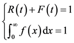 (3)
(3)
3.3.3. Important Variables: MTBF, MTTF and MTTR
The MTBF (Mean Time Between Failures) for a repairable product is the predicted elapsed time between failures during operation and the MTTF (Mean Time To Failure) for non-repairable products. The MTBF and MTTF are also considered as other forms of reliability; they are used to determine the number of failures per million hours for a product. The MTBF can be expressed in terms of the expectation value of the density function or as the total operating time divided by the number of failures. The MTBF can be expressed in different ways, including
 (4)
(4)
where  is the total operating time and N is the number of failures. An effective MTBF can also be evaluated through the following equation:
 (5)
(5)
where τ is the maintenance interval (i.e., the system is restored to “as good as new” every T hours).
Thus, the average failure rate can be determined from the inverse of the MTBF (with repair) relation, e.g., as
 (6)
(6)
In aircraft engineering, many variations of the MTBF, such as the mean time between system aborts (MTBSA), the mean time between critical failures (MTBCF) and the mean time between unit replacements (MTBUR), are used.
In many other situations, engineers prefer to use the Mean Time to Failure (MTTF) instead of the MTBF in cases where a system is replaced after a failure. The MTTFd (d for danger) is an extension of the MTTF and is only concerned with failures that would result in dangerous conditions.
The algebraic expression of the MTTF is
 (7)
(7)
where E(x) is the expectation function.
The Mean Time To Repair (MTTR) is the time needed to repair or to simply replace a failed component. In an operational system, repair generally means the suffering of a prohibitive cost, especially when spare parts are unavailable. To avoid such a situation, it is more beneficial to replace the failed item with a new item and perform maintenance actions on the removed item. Such a removed item could be reused another time to replace a failed item. This solution can increase the availability of the aircraft and minimize costs due to immobilization; this can be studied as a part of the science of maintainability.
From the graphic in Figure 6, the MTBF, MTTF and the MTTR can be easily determined.
3.3.4. Maintainability
Maintainability is considered as the actual likelihood of performing an efficient maintenance process inside a suitable recommended time frame within an expected level of

Figure 6. The life cycle of a product subject to failures.
confidence having the provided workforce, levels of skills, test-related equipment, specialized information, operational and repair information, and routine maintenance assistance agencies and establishments and under precise conditions {Johnson Jr, 1988 #13; Teal, 2001 #15; Tsagkas, 2014 #42}. In short, maintainability determines the actual straightforwardness and swiftness with which a unit is repaired toward a functional condition following a malfunction. This generally resembles product reliability evaluation, with the exception that the particular random element of concern within a maintainability assessment will be the time-to-repair as opposed to the time-to-failure. To provide an example, when it is declared that a given item possesses 90% maintainability when considering a time frame of one hour, this implies that there is simply 90% likelihood that the particular item could be restored inside an hour. Moreover, whenever time-dependent estimations are performed, either availability, denoted as A(t), or unavailability, denoted as U(t), estimations are conducted. Whenever one mixes product maintainability assessment with product reliability evaluation, they are able to receive several valuable outcomes with regard to the general performance (availability, uptime, downtime, etc.), which assists in enhancing judgments concerning the structure and/or operation associated with a repairable product.
3.3.5. Availability
In aircraft reliability engineering, the concept of availability is very important to measure [13] [16] . In critical systems, such as those in the aircraft industry, different categories of availability can be defined, from which a common operational availability (a measure of system performance) within RM relates concepts through system availability.
Availability is the likelihood that a chosen unit is performing satisfactorily at all times. The three varieties of availability indicators can be described as follows:
Instantaneous availability, A(t), is the likelihood that a unit is working adequately at time t and is similar to the reliability when considering non-repairable units and steady-state availability. Stationary availability, UTR (read as Up to Ratio), is the proportion of the average uptime over an infinite horizon.
Average availability is defined on an interval of the real domain and is denoted as AV(t). It is defined as the expected proportion of time when the system is in operation on the time interval (0, T).
These indicators are expressed as follows:
 (8)
(8)
where μ and λ are the MTBF and the MTTR, respectively,
 (9)
(9)
and
 (10)
(10)
3.3.6. Maintenance
As defined by AFNOR (the French Association for Standardization), maintenance is the set of operations used to maintain or restore a property to a specified condition so that it is able to provide a specific service. Maintenance functions include troubleshooting and repair actions, adjustment, revision, monitoring and the verification of hardware equipment (machinery, vehicles, manufactured goods, etc.) or even intangibles (software).
There are two complementary ways of organizing maintenance actions [15] [42] - [45] :
Corrective maintenance: A maintenance process is conducted to determine, isolate, and resolve a problem to ensure that the failed items, equipment, or system may be repaired to a working status inside the specifications or restrictions found for in-service operations. This is subdivided into the following:
Palliative maintenance: Troubleshooting (i.e., temporary) of the equipment, enabling it to provide all or part of a required function. The troubleshooting must however be followed by remedial action as soon as possible.
Curative maintenance: Repair consisting of a restoration to the original state.
Preventive maintenance, which consists of work on equipment before a failure occurs in an attempt to prevent failure. Preventive maintenance is subdivided into the following:
Systematic maintenance: Actions performed systematically according to a schedule (at fixed time intervals) or at intervals of use (hours of operation, number of units produced, number of movements, etc.).
Conditional maintenance: Conducted following statements, measures, and controls revealing the state of degradation of the equipment.
Predictive maintenance: Performed after analysis of the evolution of the degradation state of equipment.
There are three main maintenance classes of operations that are used to ensure aircraft remain in service, termed as MRO: Maintenance, Repair and Overhaul [46] [47] :
Maintenance: Maintenance is preventive and is conducted as per servicing schedules at stipulated periodicities. At times, based on condition monitoring data, predictive maintenance can also be conducted. To conduct periodic maintenance operations, statistical analysis of the failure rates can assist the decision maker in reviewing the maintenance periodicities and/or adopting reliability improvement measures.
Repair: Corrective operations are performed according to condition monitoring data and symptoms, and the observations made by the pilot/crew are considered for fault diagnosis. The faulty component is repaired or replaced as per the scope. The complete system is tested for serviceability. If the system fails before the next scheduled maintenance, then the reasons for the failure need to be established. The repair/restoration procedure can be reviewed accordingly.
Overhaul: Overhaul is a detailed examination of all components and subsystems and is a combination of preventive, corrective and predictive maintenance.
Overhaul is performed in an industrial-type facility. Thus, the level of inspection and repairs, the quantum of the job executed, the extent to which the systems are restored to as good as new states and the guaranteed period of failure-free operation are some of the factors that determine the performance of an overhaul [46] .
In reliability and MRO engineering, decision makers use performance indexes for determining if an aircraft, a system or simply a component of the airplane are performing their missions satisfactorily. Such indexes include the following:
Operational Availability Index
 (11)
(11)
where:
 : number of aircraft of a certain type (e.g., the A320);
 : number of days aircraft i is serviceable;
 : number of days aircraft i should have been serviceable.
Such an index can be used as a measure of the maintenance efficiency of a certain type of aircraft.
Aircraft Uptime
 (12)
(12)
where:
 is the actual aircraft uptime and
  is the desired aircraft uptime.
The desired aircraft uptime can be provided as a target for the maintenance managers before the start of the measurement/assessment period.
Time Index
 (13)
(13)
where  is the time index;
  is the desired inspection; and
  is the extra time.
The time index ( ) is the ratio between the difference between the desired inspection time and the extra time to the desired inspection time.
Efficiency of Fault Diagnosis
 (14)
(14)
where:
 : signal-to-noise ratio, in which smaller is better;
 : time taken for correct rectification of each failure;
n: number of failures over a given period.
Other indexes, such as the Environmental index and the As Good As New index, can be defined [46] .
3.4. Predictive Methods and Tools for Reliability Analysis and Evaluation
A proper prediction of aircraft reliability and performance is an extremely important step before, during and after the design process. Reliability can also be considered as a performance and payload metric that can sell an aircraft more so than any other metric. The worst scenario can manifest itself as soon as the aircraft takes off for the first time and can devastate a development program if not cancel it before production begins. To avoid such problems, designers use proven methods and standards. However, there are important limitations that must be taken into account, and aircraft designers are advised to gain experience with these methods by applying them to existing aircraft for which performance data have been previously published. This will build experience and an understanding of their accuracy, which serves them well when assessing the performance of new designs [5] .
Several methods and tools are used to represent the aircraft design for determining performance indices, such as the reliability value, and to predict the risk of observing a breakdown in any subsystem of the aircraft. The most used tools are the following.
3.4.1. Reliability Block Diagram
Reliability design begins with the development of a model. The graphical representation of the model is called a Block Diagram (RBD) [35] . A block diagram is a graph composed of nodes (rectangles) and edges (lines). A node edge may represent a subsystem, such as the avionic system, or a component such as a simple electrical circuit. The inter-relations between these nodes are edges (direct or undirected arcs), which provide the connection between subsystems and components. This connection may be physical, logical or of another type. Once the diagram is drawn, and when the reliability of each element of the system is known, it is possible to determine the reliability of the entire system. The method is simple to apply; an example is presented in Figure 7.
Suppose that the reliability value of each component of the Pratt & Whitney F100 Engine is given in the following table. It is easy to determine the reliability of this engine (Table 3) [7] [29] .

Figure 7. Block reliability diagram of the Pratt & Whitney F100 engine.
Table 3. The P&W engine components and their reliabilities.
The reliability of the engine is computed as follows:
 (15)
(15)
If we suppose that the aircraft uses two engines to fly (Figure 8), the reliability of the engine system is as follows:
Case 1: We assume that, following the failure of one engine, the second engine can be used to perform a landing at the nearest airport. Both engines are in parallel.
 (16)
(16)
Case 2: We assume that, following the failure of one engine, the second engine will not support flight alone. Then, we consider that both the engines are in series, and the reliability is
 (17)
(17)
Note that the values given to the reliabilities of the components of the Pratt & Whitney F100 Engine are fictitious and do not reflect the true values determined by Pratt & Whitney.
3.4.2. Failure Modes and Effects Analysis
FMEA is a predictive method used for analyzing the reliability of a system [21] [23] - [25] [48] - [50] . This method helps to identify potential failures whose consequences affect the proper functioning of the system and for estimating the risks associated with the occurrence of these failures so that corrective actions can be taken during the design, implementation or exploitation phases of a system. FMEA is known to be an inductive method that can be applied to any system that risks failure and not meeting its objectives of reliability, maintainability and safety.
The use of FMEA is not a recent development. FMEA was established as a risk analysis and risk management methodology by the U.S. military during the Second World War. In 1949, it became a directive called “MIL-P-1649, Procedures for Performing a Failure Mode, Effects, and Criticality Analysis” [51] . FMEA methods and applications were officially accepted as a recommended practice for aerospace engineering by the SAE beginning in 1967 under ARP926, Fault/Failure Analysis Procedure, and became a standard part of the design process in the aerospace industry by the 1980s [22] . During its initial application, FMEA and its extended method, called FMECA (C: Criticality), were used for aerospace/rocket development. They have been helpful in avoiding preventable failures. FMEA was also used in the project of the Boeing Commercial Airplane Group to substantiate the safety and reliability of design changes for two generations of the Boeing 737 commercial airliner: the 737-300/400/500 series, first produced in the mid-1980s, and the “next generation” 737-600/700/800/900 series, first produced in the late 1990s and early 2000s [23] .
 (a) (b)
Figure 8. RBD of parallel (a) and series (b) Configurations.
FMEAs are developed around the following points:
To postulate each failure mode based on the functional requirements;
To determine the appropriate effects;
To determine the severity of the effect;
To postulate on the possible causes;
Occurrence (relative probability).
When the FMEA is completed, a risk assessment analysis is performed for all previously identified failures, resulting in the calculus criticality from the estimated occurrence of indices, severity and detectability. The criticality index is then established according to the following equation:

where F is the Occurrence index.
This index represents the probability that the cause of failure will appear and cause the potential failure mode. For this, we must simultaneously consider the likelihood of the cause and the likelihood that this cause leads to the failure. We can do this using an indexed list enumerated from 1 to 5, defining the severity (minor, moderate, major, catastrophic and security) and the criteria of the conditions of realization of the types of severity.
G: Severity index
This index is based on an indexed list enumerated from 1 to 5, the effects caused by the failures and their occurrence (nonexistent, rare, occasional, frequent, and systematic), and their relative criteria.
D: Detectability index
This index defines the probability that the failure mode causes the most serious effect without the failure being detected beforehand. This index is enumerated from 1 to 4, and the corresponding detectability elements are systematic, occasional, difficult, and impossible.
3.4.3. Fault Tree Analysis
Fault tree analysis (FTA) is a malfunction evaluation technique through which an unwanted system event is examined by using Boolean logic to incorporate a number of lower level events. The evaluation endeavors to model and evaluate malfunction pro- cesses. FTA is essentially composed of logic diagrams that demonstrate the condition of the machine and that are created using visual design techniques. This is a significantly more formalized top-down strategy for pinpointing the actual causal links among functional breakdowns in addition to their antecedents in events or problems related to lower level parts. The FTA commences with the system-level malfunction or consequence that experts desire to comprehend, subsequently continuing to the system from the top-end level to the root processes and elements (see Figure 9).
The evaluation produces a graphical portrayal of the combinations of subsystem and element failures that can lead to the system event. The fault tree uses common notations of Boolean logic to indicate precursor or lower level events that will occur individually (“or gate”) or in combination (“and gate”) to result in the higher level event.
The subsequent figure provides an example made available from SAE-ARP26 Rev. B [22] .
3.5. Probability Risk Assessment
The Probability Risk Assessment (PRA) technique was presented in 1970 and rapidly became a life-cycle resource for assisting design, fabrication, and processes. PRA includes more complex characteristics, for instance, a clear explanation of products at their end-of-life. In PRA, a risk occurrence is subjective and essentially quantified through a magnitude or severity, which is a range of values, along with the probability of occurrence intensity. This particular potential risk is known as Quantitative Risk Assessment (QRA). In QRA, degree and probability are indicated using denominations, for example, high, medium, and weak; additional details are presented in Table 4,
where:
Class I: Not acceptable within any specific condition;
Class II: Undesirable: tolerable as long as risk minimization is impracticable or in case the expenses are blatantly excessive compared to the improvement gained;
Table 4. A typical risk class matrix in IEC 61508.

Figure 9. Example of a failure tree analysis (graph) of an aircraft engine failure.
Class III: Tolerable when the expense of risk minimization might exceed the improvement;
Class IV: Acceptable the way it is, even though it might need to be monitored.
4. Conclusion
Many serious accidents were recorded in previous decades, even though the crashed aircrafts were among the safest allowed to fly because they respected all the security conditions imposed by international agencies for security, safety and regulation worldwide. Despite the great progress in technology and processes, there remains much to be done to reduce the number of aircraft accidents to zero. Scientific solutions exist for this purpose; they simply need to be applied properly. Among them, reliability engineering is highly developed and implemented in many areas of everyday life, from the automotive industries to manufacturing. Many techniques and methods have been used to solve problems in engineering, management, production and even in the health sector. Reliability as a science has been incorporated into the life cycle of aircraft. In this paper, we have discussed and analyzed problems and their solutions applied to the aircraft industry. We have presented the reliability as a performance index alongside other indices such as maintainability, availability, MTTF, MTTR and MTBF. We have also introduced design for reliability for organizing and analyzing the different steps that consider reliability as a main activity for increasing the safety of aircraft. In addition, for designing an excellent program for reliability, we have discussed some predictive models, such as FMEA and FMECA, and rigorous standards for determining the failure rates of critical components and systems, from which the reliability can be evaluated. Finally, this paper demonstrated that reliability is crucial to be considered in all phases of the life cycle of an aircraft.
Acknowledgements
The authors would like to acknowledge the support of the Research Chair in Management of Aeronautical Projects of the University of Quebec at Trois-Rivières.
Cite this paper
Vieira, D.R., Rebaiaia, M.-L. and Chain, M.C. (2016) The Application of Reliability Methods for Aircraft Design Project Management. American Journal of Industrial and Business Management, 6, 967-992. http://dx.doi.org/10.4236/ajibm.2016.69094
References
- 1. Airbus (2016) Final Assembly and Tests.
http://www.airbus.com/company/aircraft-manufacture/how-is-an-aircraft-built/final-assembly-and-tests/ - 2. Alcouffe, C. and Corrégé, N. (2004) Structures de Gouvernance dans l’entreprise étendue: L’exemple d’Airbus [Governance Structures in the Extended Enterprise: The Example of Airbus (No. 393)]: LIRHE-Unité mixte de recherche [Joint Research Unit CNRS/UT1o]. Université des Sciences Sociales de Toulouse/Social Sciences University of Toulouse.
- 3. Boeing (2015) Current Market Outlook 2015-2034.
http://www.boeing.com/resources/boeingdotcom/commercial/about-our-market/assets/downloads/Boeing_Current_Market_Outlook_2015.pdf - 4. Altfeld, H.-H. (2010) Commercial Aircraft Projects: Managing the Development of Highly Complex Products. Ashgate, Burlington.
- 5. Johansson, C. (2013) On System Safety and Reliability in Early Design Phases: Cost Focused Optimization Applied on Aircraft Systems. Linköping University, Linköping.
- 6. Kerzner, H.R. (2013) Project Management: A Systems Approach to Planning, Scheduling, and Controlling. John Wiley, New York.
- 7. Mattingly, J.D. (2002) Aircraft Engine Design. American Institute of Aeronautics and Astronautics, Reston.
- 8. Gudmundsson, S. (2013) General Aviation Aircraft Design: Applied Methods and Procedures. Butterworth-Heinemann, Oxford.
- 9. Sutter, J. and Spenser, J. (2010) 747: Creating the World’s First Jumbo Jet and Other Adventures from a Life in Aviation. HarperCollins, New York.
- 10. Thamhain, H. (2013) Managing Risks in Complex Projects. Project Management Journal, 44, 20-35.
http://dx.doi.org/10.1002/pmj.21325 - 11. Amalberti, R. (1996) La Conduite de Systèmes à Risques: Le Travail à L’hôpital. Presses Universitaires de France, Paris.
- 12. Del Castillo, A. and Firoozmand, F. (Eds.) (2009) Development of a Reliability Program for Adjusting Aircraft Functional Check Task Intervals. 3rd CTA-DLR Workshop on Data Analysis & Flight Control, São José dos Campos, 14-16 September 2009, 1-5.
- 13. Johnson Jr., A.M. and Malek, M. (1988) Survey of Software Tools for Evaluating Reliability, Availability, and Serviceability. ACM Computing Surveys, 20, 227-269.
http://dx.doi.org/10.1145/50020.50062 - 14. Susova, G.M. and Petrov, A.N. (Eds.) (1997) Markov Model-Based Reliability and Safety Evaluation for Aircraft Maintenance-System Optimization. Annual Reliability and Maintainability Symposium, Philadelphia, 13-16 January 1997, 29-36.
http://dx.doi.org/10.1109/RAMS.1997.571660 - 15. Teal, C. and Sorensen, D. (Eds.) (2001) Condition Based Maintenance. 20th Conference on Digital Avionics Systems, Daytona Beach, 14-18 October 2011, 3B2/1-3B2/7.
- 16. Tiassou, K. (2013) Aircraft Operational Reliability: A Model-Based Approach and Case Studies. INSA de Toulouse.
- 17. Bensoussan, A. (Ed.) (2013) Probabilistic Design for Reliability (PDfR) in Space Electronics and Photonics: A Change of Vision. 2013 European Microelectronics Packaging Conference (EMPC), Grenoble, 9-12 September 2013, 1-7.
- 18. Silverman, M. and Kleyner, A. (Eds.) (2012) What Is Design for Reliability and What Is Not? Annual Reliability and Maintainability Symposium (RAMS), Reno, 23-26 January 2012, 1-5.
- 19. Suhir, E. (2012) When Adequate and Predictable Reliability Is Imperative. Microelectronics Reliability, 52, 2342-2346.
http://dx.doi.org/10.1016/j.microrel.2012.07.037 - 20. Silveira, E., Atxaga, G. and Irisarri, A. (2010) Failure Analysis of Two Sets of Aircraft Blades. Engineering Failure Analysis, 17, 641-647.
http://dx.doi.org/10.1016/j.engfailanal.2008.10.015 - 21. Su, X., Deng, Y., Mahadevan, S. and Bao, Q. (2012) An Improved Method for Risk Evaluation in Failure Modes and Effects Analysis of Aircraft Engine Rotor Blades. Engineering Failure Analysis, 26, 164-174.
http://dx.doi.org/10.1016/j.engfailanal.2012.07.009 - 22. SAE-ARP26 Rev B (1997) Fault/Failure Analysis Procedure. SAE International, Troy.
- 23. Berman, B. (2003) Effective Risk Management and Quality Improvement by Application of FMEA and Complementary Techniques.
http://www.paragonrx.com/experience/white-papers/effective-risk-management-and-quality-improvement - 24. Xie, M., Yao, H. and Zhao, Z. (2011) Failure Analysis on Tread Throw of the Tire of B737-800 Airplane. Engineering Failure Analysis, 18, 789-796.
http://dx.doi.org/10.1016/j.engfailanal.2010.12.024 - 25. Kumari, S., Satyanarayana, D. and Srinivas, M. (2014) Failure Analysis of Gas Turbine Rotor Blades. Engineering Failure Analysis, 45, 234-244.
http://dx.doi.org/10.1016/j.engfailanal.2014.06.003 - 26. Airbus (2015) Airbus Global Market Forecast 2015-2034.
http://www.airbus.com/company/market/forecast/ - 27. Hammer, J. (2016) The Real Story of Germanwings Flight 9525.
http://www.gq.com/story/germanwings-flight-9525-final-moments - 28. 7sur7. (2015) La Durée de Vie D’un A320 est de 35 à 40 Ans [The Life Time of an A320 is 35 to 40 Years].
http://www.7sur7.be/7s7/fr/33226/Crash-d-un-Airbus-A320-en-France/article/detail/2263210/2015/03/24/La-duree-de-vie-d-un-A320-est-de-35-a-40-ans.dhtml - 29. Nieto, P.G., Garcia-Gonzalo, E., Lasheras, F.S. and de Cos Juez, F.J. (2015) Hybrid PSO-SVM-Based Method for Forecasting of the Remaining Useful Life for Aircraft Engines and Evaluation of its Reliability. Reliability Engineering and System Safety, 138, 219-231.
http://dx.doi.org/10.1016/j.ress.2015.02.001 - 30. Vieira, D.R. and Bravo, A. (2016) Life Cycle Carbon Emissions Assessment Using an Eco-Demonstrator Aircraft: The Case of an Ecological Wing Design. Journal of Cleaner Production, 124, 246-257.
http://dx.doi.org/10.1016/j.jclepro.2016.02.089 - 31. Associated Press (2014) Malaysia Airlines Flight MH370: Airlines Urge More Security Checks.
http://www.cbc.ca/news/world/malaysia-airlines-flight-mh370-airlines-urge-more-security-checks-1.2593720 - 32. Harry, M.J. and Schroeder, R.R. (2005) Six Sigma: The Breakthrough Management Strategy Revolutionizing the World’s Top Corporations. Currency, New York.
- 33. MIL-217 (1991) Military Handbook: Reliability Prediction of Electronic Equipment: MIL-HDBK-217F: 2 December 1991. Department of Defense, Washington DC.
- 34. Saglimbene, M. (Ed.) (2009) Reliability Analysis Techniques: How They Relate to Aircraft Certification. Annual Reliability and Maintainability Symposium (RAMS), Fort Worth, 26-29 January 2009, 218-222.
http://dx.doi.org/10.1109/rams.2009.4914678 - 35. Rebaiaia, M.-L. (2011) A Contribution to the Evaluation and Optimization of Networks Reliability, Université Laval, Québec.
- 36. MIL-STD-1553 (2010) Designer’s Guide. 6th Edition, Department of Defense, Washington DC.
- 37. Gu, H. and Fu, G. (2013) Failure Analysis of the Adhesive Joint of Microwave Ferrite Phase Shifter. Engineering Failure Analysis, 33, 367-380.
http://dx.doi.org/10.1016/j.engfailanal.2013.06.003 - 38. Busic, Z., Lovrc, Z., Amc, E., Busic, V., Lovrc, L. and Markovc, I. (2006) War Injuries of the Extremities: Twelve-Year Follow-Up Data. Military Medicine, 171, 55-57.
http://dx.doi.org/10.7205/MILMED.171.1.55 - 39. Debrincat, J., Bil, C. and Clark, G. (2013) Assessing Organizational Factors in Aircraft Accidents Using a Hybrid Reason and AcciMap Model. Engineering Failure Analysis, 27, 52-60.
http://dx.doi.org/10.1016/j.engfailanal.2012.06.003 - 40. Ellery, A., Kreisel, J. and Sommer, B. (2008) The Case for Robotic On-Orbit Servicing of Spacecraft: Spacecraft Reliability Is a Myth. Acta Astronautica, 63, 632-648.
http://dx.doi.org/10.1016/j.actaastro.2008.01.042 - 41. Wong, C.N., Huang, H.-Z. and Li, N. (2013) Fourier Series Based Reliability Analysis of Aeroengine Turbine Blade under Linear Fuzzy Safety State. Engineering Failure Analysis, 31, 268-280.
http://dx.doi.org/10.1016/j.engfailanal.2013.02.007 - 42. Tsagkas, V., Nathanael, D. and Marmaras, N. (2014) A Pragmatic Mapping of Factors Behind Deviating Acts in Aircraft Maintenance. Reliability Engineering and System Safety, 130, 106-114.
http://dx.doi.org/10.1016/j.ress.2014.05.011 - 43. Feng, Q., Li, S. and Sun, B. (2014) A Multi-Agent Based Intelligent Configuration Method for Aircraft Fleet Maintenance Personnel. Chinese Journal of Aeronautics, 27, 280-290.
http://dx.doi.org/10.1016/j.cja.2014.02.016 - 44. Kumar, U.D., Crocker, J. and Knezevic, J. (Eds.) (1999) Evolutionary Maintenance for Aircraft Engines. Annual Reliability and Maintainability Symposium (RAMS), Washington DC, 18-21 January 1999, 62-68.
- 45. Liang, Z., Feng, Y., Zhang, X., Wu, T. and Chaovalitwongse, W.A. (2015) Robust Weekly Aircraft Maintenance Routing Problem and the Extension to the Tail Assignment Problem. Transportation Research Part B: Methodological, 78, 238-259.
http://dx.doi.org/10.1016/j.trb.2015.03.013 - 46. Raju, V., Gandhi, O. and Deshmukh, S. (2012) Maintenance, Repair, and Overhaul Performance Indicators for Military Aircraft. Defense Science Journal, 62, 83-89.
http://dx.doi.org/10.14429/dsj.62.881 - 47. Rodrigues, D. and Lavorato, P. (2016) Maintenance, Repair and Overhaul (MRO) Fundamentals and Strategies: An Aeronautical Industry Overview. International Journal of Computer Applications, 135, 21-29.
http://dx.doi.org/10.5120/ijca2016908563 - 48. Spasic, D.M., Stupar, S.N., Simonovic, A.M., Trifkovic, D. and Ivanov, T.D. (2014) The Failure Analysis of the Star-Separator of an Aircraft Cannon. Engineering Failure Analysis, 42, 74-86.
http://dx.doi.org/10.1016/j.engfailanal.2014.03.022 - 49. Witek, L. (2006) Failure Analysis of Turbine Disc of an Aero Engine. Engineering Failure Analysis, 13, 9-17.
http://dx.doi.org/10.1016/j.engfailanal.2004.12.028 - 50. Yang, J., Huang, H.-Z., He, L.-P., Zhu, S.-P. and Wen, D. (2011) Risk Evaluation in Failure Mode and Effects Analysis of Aircraft Turbine Rotor Blades Using Dempster-Shafer Evidence Theory Under Uncertainty. Engineering Failure Analysis, 18, 2084-2092.
http://dx.doi.org/10.1016/j.engfailanal.2011.06.014 - 51. MIL-P-16594A (1955) Military Specification: Manufacture of Projectiles, Bombs, Rockets, and Guided Missile Warheads.