Modern Mechanical Engineering
Vol.06 No.01(2016), Article ID:64034,7 pages
10.4236/mme.2016.61005
Approaches for Detailed Modelling of Ultra-Precision Positioning Systems
Dominik Dahlmann, Nesrine Sassi, Berend Denkena
Institute of Production Engineering and Machine Tools, Leibniz University of Hanover, Hanover, Germany
![]()
Copyright © 2016 by authors and Scientific Research Publishing Inc.
This work is licensed under the Creative Commons Attribution International License (CC BY).
http://creativecommons.org/licenses/by/4.0/


Received 15 January 2016; accepted 26 February 2016; published 29 February
ABSTRACT
Nowadays, the productivity of ultra-precision machining is fundamentally limited by low feed rates because of the required accuracies in the nanometre range. An increase in motion dynamics leads to disturbances that affect the toolpath’s accuracy. Existing control concepts are not able to reliably detect and compensate the deviations caused by increased dynamics. This paper com- pares modelling approaches for ultra-precision positioning systems aiming to predict and com- pensate occurring deviations.
Keywords:
Ultra-Precision, Modelling, Compensation

1. Introduction
Ultra-precision machining is a key technology for the manufacturing of optical components with a surface roughness under 20 nm and form deviations under 1 µm [1] . These high accuracy requirements restrict the processing dynamics of ultra-precision machining [2] . An increase in dynamics leads to relevant disturbances such as spindle unbalances, tilting moments and overshooting of the machine axes [3] . The disturbance effects must be compensated in order to achieve the accuracy required by ultra-precision applications. For this purpose, reactive compensation methods that rely solely on measured values are insufficient. The main reason is that the relevant control variables cannot always be measured directly. For instance it is not always possible to place a sensor at the desired position due to poor accessibility.
Hence, a novel approach for the compensation of the disturbance effects is needed to overcome these limitations. For this purpose, predictive compensation methods have great potentials [4] -[6] . The idea behind these methods is to predict the deviations before they occur based on a system’s model. Thus deviations can be compensated reliably and in time.
The accurate modelling of ultra-precision positioning systems requires the consideration of different error influences. In addition to geometric and thermo-elastic errors, deviations due to the structural static and dynamic compliance influence the toolpath accuracy significantly. Various model-based methods for the compensation of geometric errors of precision and ultra-precision machine tools have been proposed in literature [7] [8] . However, predictive model-based compensation of thermo-elastic errors and errors due to the structural static and dynamic compliance for ultra-precision machine tools has not been investigated so far. Structural modeling of ultra-precision machines has been mainly used to analyze and optimize the machine dynamic performance during the development stage. For this purpose, FE modeling is widespread [9] [10] .
On the contrary, for conventional machine tools, much research work has been conducted in the model-based compensation of the different error influences. Structural models aiming to compensate dynamic errors can be made up of rigid bodies coupled with spring-damper units [4] . Another approach consists of reducing the corresponding FE models [11] -[13] .
Based on such conventional modeling techniques, this paper presents approaches for building a structural model of an ultra-precision positioning system. The model is intended to compensate the deviations due to structural compliance of the system and increased process dynamics. The next section presents the ultra-preci- sion demonstrator, to which the modelling approaches in this paper refer.
2. Ultra-Precision Demonstrator
The demonstrator shown in Figure 1 is a 2-axis-positioning system in cross table configuration. It consists of a precision machine linear axis with aerostatic bearings and a novel electromagnetically guided machine axis on top supporting the workpiece table. The concept of the demonstrator has been developed in consideration of the principles of ultra-precision design [1] . In order to reduce tilting moments a box-in-box-design for the cross table has been chosen. Both axes are driven by ironless linear motors to avoid attraction forces.
Errors, which are caused by the dynamic compliance of the aerostatic guide and the machine structure, can be predicted using a model of the positioning system. Correcting values are then assigned to the convenient actuators depending on the amplitude and the frequency range of the errors. The linear motors are suitable for the compensation of deviations with high amplitudes and low frequencies. The actively controlled magnet actuators of the upper axis have great potentials to compensate high-frequency deviations with small amplitudes [14] . Figure 2 shows the concept of the intended model-based error compensation for the presented positioning system.
3. Requirements on the Model of the Ultra-Precision System
In order to apply predictive compensation methods for the ultra-precision system high resolution requirements are set for the model to correctly predict the errors in nm range. To achieve both accuracy and real-time capability for the compensation, an accurate state space model of the positioning system is built and then divided into sub-models with different validity ranges.
The accurate modelling of ultra-precision positioning systems requires the consideration of different error influences. In addition to kinematic and thermo-elastic errors, deviations due to the structural static and dynamic compliance influence the toolpath accuracy significantly. Thus an accurate model of the mechanical system is
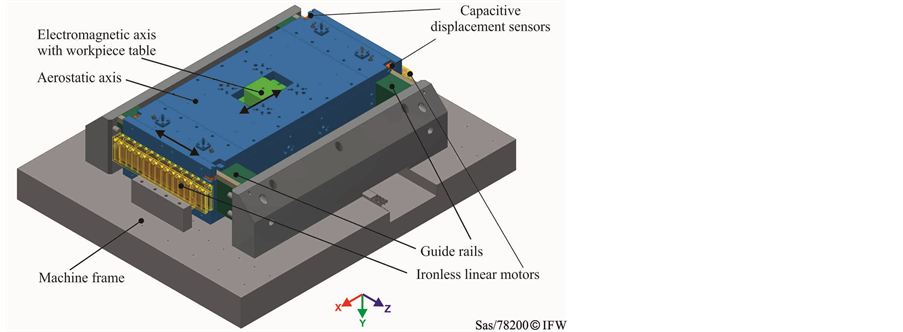
Figure 1. Ultra-precision demonstrator.

Figure 2. Concept of the model-based error compensation.
necessary. With regard to the required accuracies of ultra-precision applications, a positioning accuracy of 0.1 µm is demanded. Thus a resolution of 1 nm is specified for the structural model.
A high resolution FE model reproduces the behaviour of the mechanical system with the highest accuracy. However, it is not efficient to consider it as the final accurate model because of the high untenable computational time. The high resolution FE model is taken as a reference for the final accurate model. The latter should represent the real system with the resolution demanded using as many degrees of freedom (DOF) as necessary. A multi body state space model of the aerostatic axis with 12 DOF was built in a digital block simulation environment (DBS) according to the formalism presented in [15] . This model assumes that all system’s components are rigid, except the guides and bearings, which are modelled with spring-damper units. In order to evaluate this elementary model the static deformation is compared with the deformation of the reference FE model at an exemplary excitation point.
Here, a disturbance force of 10 N due to a possible inhomogeneity at the aerostatic bearings is assumed as shown in Figure 3. The calculated discrepancy of 86% implies that the elementary model has to be detailed extensively.
4. Approaches for Building the Sufficiently Accurate Structural Model
In order to determine the sufficiently high level of detail for the accurate model two approaches have been considered (Figure 4).
4.1. Bottom-Up Approach
The aim of this approach is to generate a sufficiently detailed model with an explicit structure of the state space matrices. That means that the stiffness and damping elements of each component and of the coupling points can be localized exactly. The in-depth knowledge of the model’s structure helps to divide the primary model into sub-models without affecting the modelling accuracy.
In order to achieve an explicit structure of the accurate primary model a methodology has been used to systematically detail the state space model described in the previous section. The methodology is based on sensitivity analyses of the system’s components. According to the results of these analyses the component that should be detailed and the required level of detail for the direction of interest are selected. The discretization of a component is achieved by the spatial division of the bodies into equal body-parts that are coupled with spring-damper units. Figure 5 shows exemplarily the detailing procedure of the guide rails along the z-direction. According to the defined detailing direction and the intended level of detail the masses, inertias and coupling points of the new body-parts are calculated. The stiffness of the springs in between the body-parts is identified by comparison with the FE model. The level of detail increases until the required resolution is reached and the deviation from the reference model does not exceed 10%.
This approach enables the exact localization of the significant geometric sections for the deformation and the coupling points in-between the detailed body-parts in the model. Especially for simple geometries like for the

Figure 3. Boundary conditions of the model.

Figure 4. Approaches for building the sufficiently accurate structural model.
![]()
Figure 5. Bottom-up-approach (discretization of a component in z- direction).
guide rails the discretization is very useful at reasonable expense. However, several components for example of the electromagnetic axis have complex geometries that are asymmetric or composed of several sophisticated parts and shapes. For such geometries the appropriate manual determination of the properties of the body-parts and their integration into the model is time-consuming and complex which leads to modelling errors. In order to avoid such modelling errors another approach, described in the next section, has been followed.
4.2. Top-Down Approach
This approach is based on the reference model. The idea behind it is to export the reference FE model as a state space model to the DBS. Because of the very high number of DOF of the reference model (556,998) it is not possible to read out the state space matrices driven from this model in the DBS. That is why the reference FE model has to be reduced as much as necessary. Before the export of the matrices inputs and outputs of the system must be defined. The inputs are the application points of the driving forces and the expected disturbance forces. The outputs are the points of interest especially at the Tool Centre Point, the excitation points and the points of the measurement systems used. The latter are the capacitive distance sensors that measure the deviations of the air gap of the aerostatic bearings (Figure 1) and the linear encoders that measure the positioning error in the direction of motion.
For the reference FE model of the aerostatic axis a model order reduction of the whole system has been carried out after a modal analysis. For this purpose the number n of the modes to be extracted is defined. Using the function spmwrite provided by the FE program Ansys the mechanical system is reduced by means of the modal superposition method which expresses the response of the structure in terms of neigenmodes of the system. The n second order modal equations are then transformed into 2n first order equations. Thus a state space model of the reduced mechanical system is created. The system matrix A is described as follows [16] :
![]() with
with ![]() and
and ![]() (1)
(1)
where ![]() is the frequency of mode i,
is the frequency of mode i, ![]() is the effective modal damping of mode i and E is the unit matrix.
is the effective modal damping of mode i and E is the unit matrix.
Figure 6 shows the compliance transfer function at the defined excitation point in the direction of the applied force (Figure 3) for the high resolution model as well as for the exported reduced-order model.
Up to a frequency of 1300 Hz the reduced order model shows a good agreement with the high resolution FE model despite the very small number of DOF and the low computing time compared to the reference model. For a static simulation the computing time of the reduced order model is 0.63 s compared with 380 s for the reference model. The deviation in the static compliance between the reduced order model and the reference model is 10%. Compared with the bottom-up approach the top-down approach ensures a good correlation to the reference model with reasonable expense especially for complex geometries.
In order to get a higher correlation between the reference model and the reduced-order model, each component can be reduced separately, so that more DOF are reflected in the state space model. In this case, the exported components are coupled with the other components in the DBS and the properties of the coupling elements can be changed in this simulation environment. In particular the non-linear characteristics of the aerostatic bearings can be implemented in the DBS. On the contrary, non-linear features cannot be defined for the starting FE model because most model order reduction methods require a linear model.
The top-down approach ensures a good correlation to the reference model with reasonable expense. Especially for complex geometries modelling errors can be kept small in comparison with the bottom-up approach. The latter has the advantage of the clear structure of the state space matrices because all states are known. These are the position and orientation at the center of mass of each body or body-part. This may be helpful for the state space control of the system. By contrast, the reduced order model generated by the top-down approach has unknown states, but the positions at the defined output nodes, which are crucial for the intended compensation, are known.
5. Conclusions
The increase in dynamics for ultra-precision processes leads to significant deviations that must be compensated to reach the required accuracies in the nm range. To overcome the limitations of current control systems, predictive compensation of the errors is intended. For this purpose, a sufficiently accurate structural state space model of the ultra-precision positioning system is needed.
![]()
Figure 6. Compliance transfer functions for the high resolution and reduced order model (top-down approach) at the excitation point in the direction of the force.
In this paper, the requirements on the accuracy of the model are defined. With a high resolution FE model as a reference, two approaches for determining the sufficient level of detail are presented in this paper.
The bottom-up approach is very useful with regard to certain methods for dividing the model into sub-models. However, modelling uncertainties can occur for complex geometries mainly because of the lack of an automatic discretization procedure based on the elementary multi body model in the DBS. Results have shown that the top-down approach enables generating a structural state space model with a low number of DOF and a good correlation with the reference model. Against this background, the top-down approach is more suitable to generate sufficiently accurate models for the compensation of positioning errors of ultra-precision systems.
Acknowledgements
The authors thank the German Research Foundation for funding the research group FOR 1845 “Ultra-Precision High Performance Cutting”.
Cite this paper
DominikDahlmann,NesrineSassi,BerendDenkena, (2016) Approaches for Detailed Modelling of Ultra-Precision Positioning Systems. Modern Mechanical Engineering,06,44-50. doi: 10.4236/mme.2016.61005
References
- 1. Mekid, S. (2008) Introduction to Precision Machine Design and Error Assessment. CRC Press, Boca Raton.
- 2. Brinksmeier, E., Denkena, B., Kuhfuss, B. and Riemer, O. (2013) Muss ultrapräzision zeitund kostenintensiv sein? Mikroproduktion, 3, 44-52.
- 3. Schönemann, L., Sassi, N., Krüger, R., Bloem, A., Denkena, B. and Kuhfuä, B. (2015) Ultrapräzise Hochleistung-sbearbeitung, Teil 2: Potentiale Elektromagnetischer Linearführungen Kombiniert mit Modellbasierten Steuerung-skonzepten. Werkstattstechnik Online, 7/8, 469-474.
- 4. Peters, R., Litwinski, K., Overmeyer, L. and Denkena, B. (2013) Model-Based Feedback Control via Control Integrated Observers. 15th International Conference on Precision Engineering in Kanazawa, Kanazawa City, 22-25 July 2014.
- 5. Steinlin, M. (2013) Model Based Feed-Rate Optimization for Machine tool Trajectories. Dissertation, ETH, Zurich.
- 6. Guiassa, R. and Mayer, R. (2011) Predictive Compliance Based Model for Compensation in Multi-Pass Milling by On-Machine Probing. CIRP Annals—Manufacturing Technology, 60, 391-394.
- 7. Kong, L.B., Cheung, C.F., Toa, S., Lee, W.B., Dub, J.J. and Zhang, Z.J. (2008) A Kinematics and Experimental Analysis of Form Error Compensation in Ultra-Precision Machining. International Journal of Machine Tools & Manufacture, 48, 1408-1419.
http://dx.doi.org/10.1016/j.ijmachtools.2008.05.002 - 8. Kono, D., Matsubara, A., Yamaji, I. and Fujita, T. (2008). High-Precision Machining by Measurement and Compensation of Motion Error. International Journal of Machine Tools & Manufacture, 48, 1103-1110.
http://dx.doi.org/10.1016/j.ijmachtools.2008.02.005 - 9. Liang, Y.C., Chen, W.Q., Bai, Q.S., Sun, Y.Z., Chen, G.D., Zhang, Q. and Sun, Y. (2013) Design and Dynamic Optimization of an Ultraprecision Diamond Flycutting Machine Tool for Large KDP Crystal Machining. International Journal of Manufacturing Technology, 69, 237-244.
http://dx.doi.org/10.1007/s00170-013-5020-z - 10. Huo, D.H., Cheng, K. and Wardle, F. (2010) Design of a Five-Axis Ultra-Precision Micro-Milling Machine—Ultra Mill. Part 2: Integrated Dynamic Modelling, Design Optimisation and Analysis. International Journal of Manufacturing Technology, 47, 879-890.
http://dx.doi.org/10.1007/s00170-009-2129-1 - 11. Uhlmann, E., Eβmann, J. and Wintering, J.-H. (2012) Design- and Control-Concept for Compliant Machine Tools Based on Controller Integrated Models. CIRP Annals—Manufacturing Technology, 61, 347-350.
http://dx.doi.org/10.1016/j.cirp.2012.03.143 - 12. Jönsson, A., Wall, J. and Broman, G. (2005) A Virtual Machine Concept for Real-Time Simulation of Machine Tool Dynamics. International Journal of Machine Tools & Manufacture, 45, 795-801.
http://dx.doi.org/10.1016/j.ijmachtools.2004.11.012 - 13. Sekler, P., Voβ, M. and Verl, A. (2012) Model-Based Calculation of the System Behavior of Machine Structures on the Control Device for Vibration Avoidance. International Journal of Advanced Manufacturing Technology, 58, 1087-1095.
http://dx.doi.org/10.1007/s00170-011-3450-z - 14. Denkena, B., Guemmer, O. and Floeter, F. (2014) Evaluation of Electromagnetic Guides in Machine Tools. Annals of the CIRP, (63/1), 357-360.
http://dx.doi.org/10.1016/j.cirp.2014.03.130 - 15. Zirn, O. (2008) Machine Tool Analysis-Modeling, Simulation and Control of Machine Tool Manipulators. ETH Zurich, Institute ofMachine Tools and Manufacturing, Zurich.
- 16. ANSYS Help Guide V.15-14.18.