Modern Mechanical Engineering
Vol.4 No.3(2014), Article
ID:49346,10
pages
DOI:10.4236/mme.2014.43015
The Research about Prescribed Workspace for Optimal Design of 6R Robot
Yi Gan1,2*, Weiwei Yu1, Weiming He1,2, Junlei Wang1, Fujia Sun1
1College of Mechanical Engineering, University of Shanghai for Science and Technology, Shanghai, China
2Department of Precision Mechanics, Faculty of Science and Engineering, Chuo University, Tokyo, Japan
Email: *ganyi@usst.edu.cn
Copyright © 2014 by authors and Scientific Research Publishing Inc.
This work is licensed under the Creative Commons Attribution International License (CC BY).
http://creativecommons.org/licenses/by/4.0/


Received 15 May 2014; revised 30 June 2014; accepted 11 July 2014
ABSTRACT
Based on the D-H notation, kinematics model and inverse kinematics model of 6R industrial robots are established. Using graphical method, the boundary curve equations of the 6R industrial robot workspace are obtained. Based on the prescribed workspace, the D-H parameter optimization method of 6R industrial robots is proposed. Using the genetic algorithm to determine the structural dimensions of a 6R robot, we make sure that its workspace can exactly contain the prescribed workspace. This method can be used to reduce the overall size of the robot, save materials and reduce the power consumption of the robot during its work time.
Keywords:6R Robot, Prescribed Workspace, Optimal Design

1. Introduction
The workspace of a robot is defined as the sets of points that can be reached by the end-effecter [1] , and sometimes is known as reachable space. It is one of the main ways in the design and optimization processes of robots [2] . Based on graphical approach, Xie Jun et al. [3] analyzed the workspace of a novel series Chinese medical massage arm, and learned that the upper arm and the forearm of this kind of Chinese medical massage arm must be equal. Chen Zaili [4] presented a genetic algorithm approach for the synthesis of spatial 6-DOF parallel manipulators whose workspace must include a desired workspace with orienting capabilities on a given 3D region. M.A. Laribi [5] proposed an optimal dimensional synthesis method of the DELTA parallel robot for a prescribed workspace.
In the practical working conditions, when a robot accomplishes some special tasks, the range of motion of its end-effecter is not the whole workspace, but must be included in the whole workspace. As the range of motion usually has an irregular shape, it can be substituted by a prescribed workspace that includes this range of motion in the synthesis process of the robot [6] [7] . The prescribed workspace must satisfy two basic requirements: 1) be a regular geometric model, such as a cuboid, a cylinder or a sphere and so on; 2) must contain the entire range of motion of a robot’s end-effecter and has the minimum volume.
The method which is usually used to determine the structure parameters has the property of try and blindness. It is not only a waste of time, but also hard to obtain a robot with a compact structure. Different structure parameters are different information states of every link. Aiming at obtaining a compact structure, we can determine the structure parameters which make the robot with the shortest information distance [8] . This paper, based on a prescribed workspace, presents an optimum design method of D-H parameters for a 6R robot. This method can obtain a 6R robot with a compact structure, the sum of whose links’ lengths is smallest so that the material can be saved.
2. Analysis for the Workspace of a 6R Robot
2.1. D-H Coordinate Frames and Homogeneous Transformations of 6R Robot
A commonly used convention for selecting frames of reference in robotics applications is the Denavit and Hartenberg (D-H) convention which was firstly introduced by Jacques Denavit and Richard S. Hartenberg [9] . The D-H coordinate frames can be laid out as follows: 1) the Z-axis is in the direction of the joint axis; 2) the X-axis is parallel to the common normal, Xn = Zn× Zn-1; 3) the Y-axis follows from the X-axis and Z-axis by choosing it to be a right-handed coordinate system. Four parameters known as D-H parameters can be obtained. They are θ, d, a, α.
The model of 6R robot is shown in Figure 1 which is used on a welding production line. The D-H coordinate frames for it are established as shown in Figure 2. And the D-H parameters are shown in Table1
Let  be the homogeneous transformation matrix from the ith D-H coordinate frame to the jth one, then the following equations can be got:


where, ci = cos(θi), si = sin(θi). .
.
The transformation matrix from the base to the end-effecter is given as follows:
 (1)
(1)
2.2. Analysis and Simulation of the Workspace
Twelve messages are given by the matrix with Equation (1). nx, ny, nz, ox, oy, oz, ax, ay and az are nine pose information that determine the posture of the robot, px, py and pz are three position information that determine the position of the robot. As the scope of the workspace of a 6R robot is determined by position information, so we can just calculate px, py and pz when we analysis the workspace. px, py and pz are given with Equation (2).
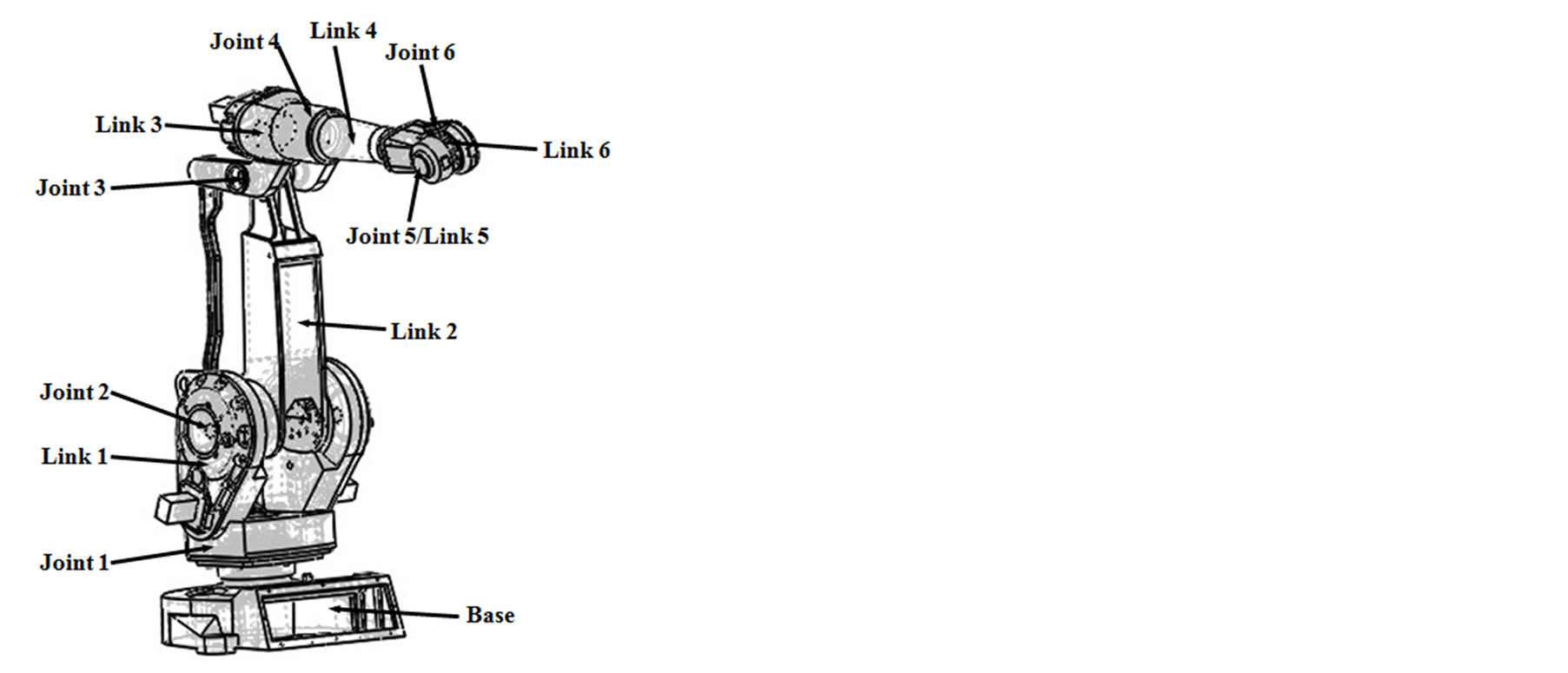
Figure 1. The three-dimensional model of the 6R robot.

Figure 2. The D-H coordinate frames of the 6R robot.

Table 1. The D-H parameters of the 6R robot.
 (2)
(2)
where c23 = cos(θ2 + θ3), s23 = sin(θ2 + θ3). From Equation (2), we can infer that the position of the end-effecter of a 6R robot is only defined by the first three joints (Joint 1, Joint 2 and Joint 3 in Figure 1). So we can define the end of the third link (the fourth joint point) as the reference work point of the 6R robot, and the set of points which the reference work point can arrive at can be defined as the workspace of the 6R robot [10] .
Let θ1 = 0˚, according to the graphical method, the cross-section of the workspace of the 6R robot on the plane X0O0Z0 can be obtained [11] . It is the area which is surrounded by the arc line Г1, Г2, Г3 and Г4 in Figure 3. The workspace of the 6R robot can be obtained by rotating the cross-section around the axis O0Z0. The three-dimensional view and the three-dimensional cross-sectional view of the workspace are respectively shown in the Figure 4 and Figure 5. From the Figure 4, we can see that the workspace is similar to a sphere. From the figure 5, we can see that there is a cavity in the workspace. When designing 6R robots, we must make sure that the cavity doesn’t intersect with the reference work point of 6R robots.
3. 6R Robot D-H Parameters Optimizing with Prescribed Workspace
3.1. Object function of Robot Structure Optimizing Based on Prescribed Workspace
According to the given n end-effecter working points of robot, the minimum rectangular can be determined which includes these n working points [6] . As shown in the Figure 6, the prescribed workspace of Δ1 is the minimum rectangular which includes all of the working points of 6R. The size of Δ1 is L1 × L2 × L3. Δ1 is symmetry relative to X0O0Y0 plane andY0O0Z0 plane. Figure 7 shows the position of Δ1 and the workspace.
The optimization objective function of Robot link length is as follows,

And the constraint conditions are,
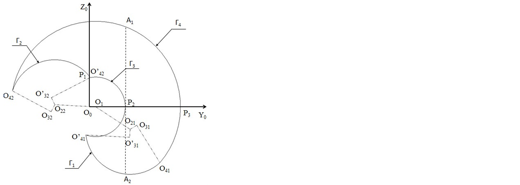
Figure 3. The section shape of the workspace of 6R robot on the  plane.

Figure 4. The three-dimensional view of the workspace.
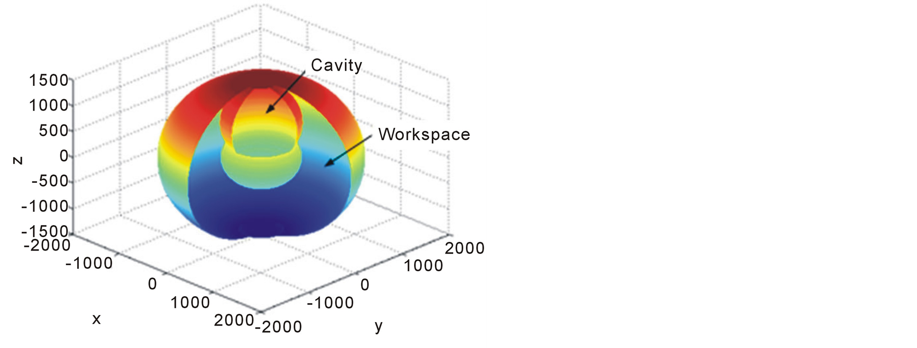
Figure 5. The three-dimensional cross-section view of the workspace.

Figure 6. The prescribed workspace.
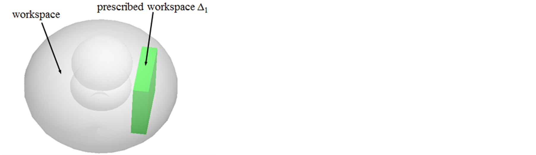
Figure 7. The prescribed workspace and the workspace.

λ1, λ2 are constants, λ1, λ2Î(0,1),and λ1 + λ2 = 1. F1(X) is sum of links length. F2(X) is the distance between the prescribed workspace and the origin O0 of the coordinate O0X0Y0Z0. xi is the length of ith link, m is the number of the links, qj is the jth joint angle, n is the number of the joints. X is m dimensional vector, X = [xi]T. Y is m + n dimensional vector, Y = [X,Q]T.
Because the positions of 6R robot end-effecters are affected by angles of the first three joints (Joint 1, Joint 2 and Joint 3 in Figure 1), the length of the first four links (Link 1, Link 2, Link 3 and Link 4 in Figure 1) can be optimized based on the prescribed workspace. The object function is:
 (3)
(3)
D(x1, x2, x3, x4) is the distance between the plane of ADD’A’ in Figure 6 of prescribed workspace and the origin O0 of the coordinate O0X0Y0Z0 in Figure 6. The value of D(x1, x2, x3, x4) is determined by the size of the internal cavity of work space.
The angle between the first axis of link 1 in Figure 1 and the horizontal plane is γ. According to the rules of D-H coordinate system, a1/cos(γ) = x1, a2 = x2, a3 = x3 and d4 = x4. And the object function can be deformed as follows, then the MinF(X) is equal to Equation (4), that is
 (4)
(4)

3.2. Constraint Conditions
3.2.1. Length of the Links Constraining
Considering the actual work requirements, the length of the links can't be small too much. The ranges of a1, a2, a3 and d4 are satisfied the following rules.
 (5)
(5)
3.2.2. Joint Angles Constraining
In Figure 3, the length of links and the joint angles were certain size, the point of O42 is in the extended line of O1 and O2 when the section area of workspace is the biggest. At the same time, .
.
Considering the actual situations and the interference problems of the structure, the rotation range of the joints should be limited. The ranges of θ2 and θ3 can be set as follows.
 (6)
(6)
3.2.3. Internal Cavity Constraining
In Figure 3, let M1 be the radius of Г2 and Г3, let M2 be the radius of Г4. Then


where  .
.
If the sum of a1, a2, a3 and d4 is the smallest, then the shadow of Δ1 on the plane of Y0O0Z0 should be on the right to the connection of A1and A2 in Figure 3. To ensure the cavity do not cross Δ1, the follows should be met.
 (7)
(7)
where,


γ1 is the included angle of the line of  and O22 and the line of O0Y0 in Figure 3.
 . γ2
. γ2
is the included angle of the line of  and O1 and the line of O0Y0 in Figure 3.
 . φ2 is the included angle of the line of
  and O1 and the line of O1 and O22 in Figure 3.
3.2.4. Key Points Constraining
Let the y coordinate of O41 less than or equal to the value of D(x1, x2, x3, x4) with the internal cavity constraining. Then the section which is on the right of the connection line of A1 and A2 is symmetry relative to the O0Y0 axis. The space of Δ2 can be got to revolve the section around the O0Z0 axis. Δ2 is symmetry relative to X0O0Y0 plane and Y0O0Z0 plane. If the point of  is in Δ2, then Δ1 must be included in Δ2 and in the workspace of 6R robot. And the points constraining is as follows.
 (8)
(8)
 (9)
(9)
where, ;
; ;
; .
.
4. Application
According to the location and distribution of a car body welding, the space sizes of prescribed workspace of one 6R robot are
 (10)
(10)
In order to avoid the movement interference, the links length and the joints angle robot are limited. l1 = 100 mm, l2 = l3 = l4 = 150 mm, –120˚ ≤ θ2 ≤ +120˚, –70˚ ≤ θ3. Let λ1 = 0.65, λ2 = 0.35 in 3th equation. Based on the genetic algorithm [12] , the optimal solution of the constraint conditions are shown in Table2 And the distance between the prescribed workspace to the plane of O0X0Y0Z0 is D(a1,a2,a3,d4) = 483.94 mm.
According to the optimal solution, the workspace can be got by the reference [13] . Δ1 was created by the methods above mentioned showing Figure 8. And Δ1 was cut respectively by the surfaces of A, B, C showing from Figure 9 to Figure 12. Δ1 was just included in the workspace and Δ1 doesn’t intersect with the internal cavity. It proves the rationality of optimization result.
Rounding the optimized size in Table 2, a1 = 100 mm, a2 = 670 mm, a3 = 150 mm, d4 = 690 mm. Then the actual robot can be created with the optimized size showing in Figure 13.
In market, the workspace of robot of IRB 2400/10 can meet the 10th equation. The contrast of these two kinds of robots shows in Table3
Table 2. The optimal solution.
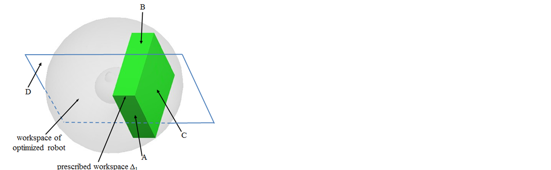
Figure 8. The prescribed workspace and the workspace of optimized robot.
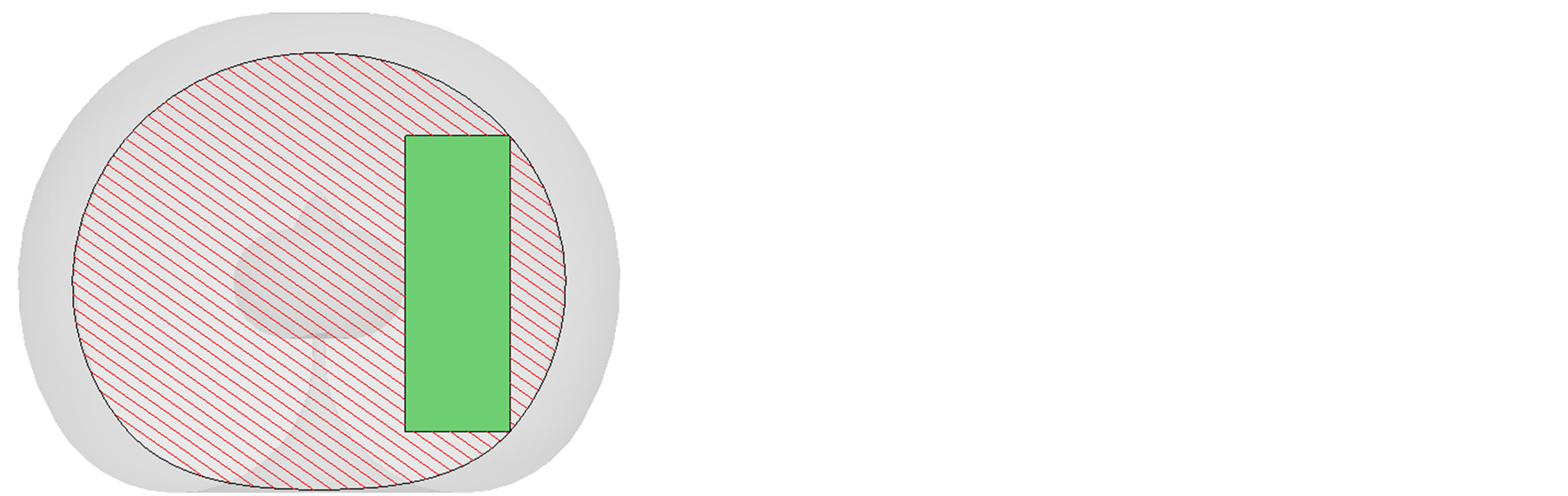
Figure 9. The section of the optimized workspace on surface A.
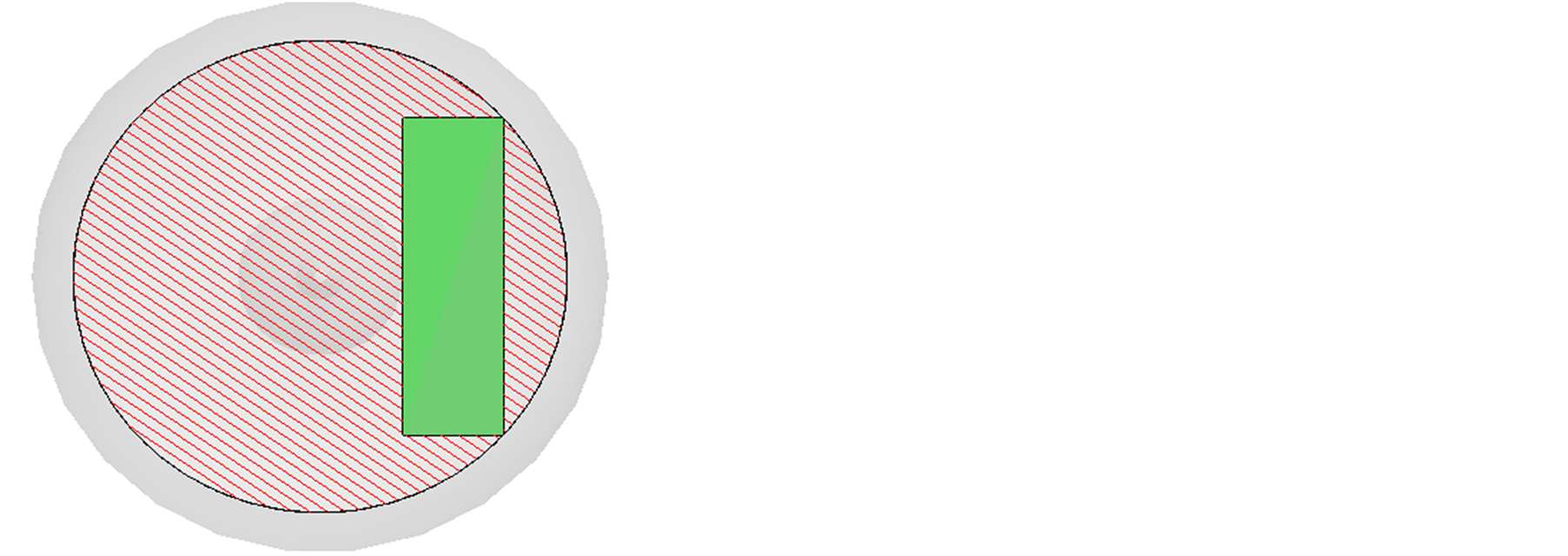
Figure 10. The section of the optimized workspace on surface B.
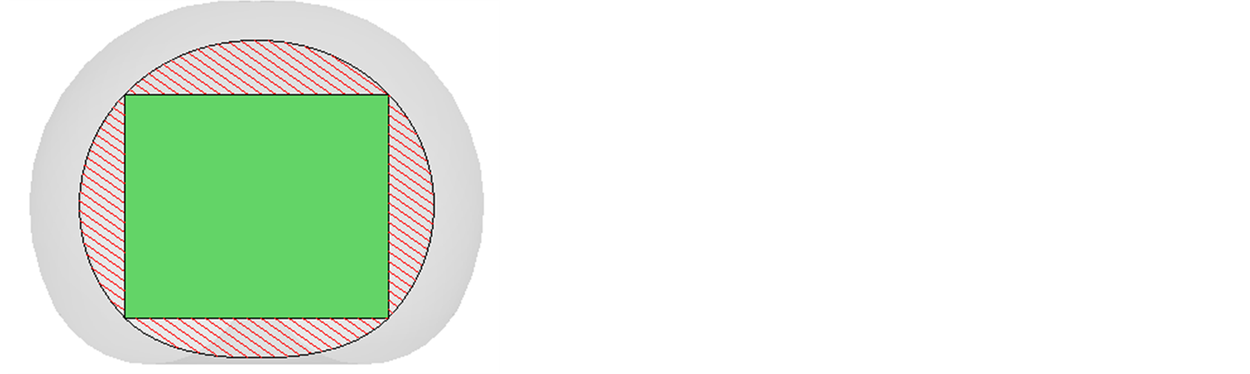
Figure 11. The section of the optimized workspace on surface C.
In Table 3, the 2 kinds of workspace volume are small difference. The sum of link length of the optimized robot is shorter than that of IRB 2400/10 robot by 85 mm. And the weight of the former is 7.89% lighter than that of the latter.
5. Conclusion
It analyzes the workspace of 6R robot to ensure the joints that affect 6R robot’s work space. And the edge curve of work space had been got by the graphic method. Matlab was used to establish the simulation model of 6R robot work space.
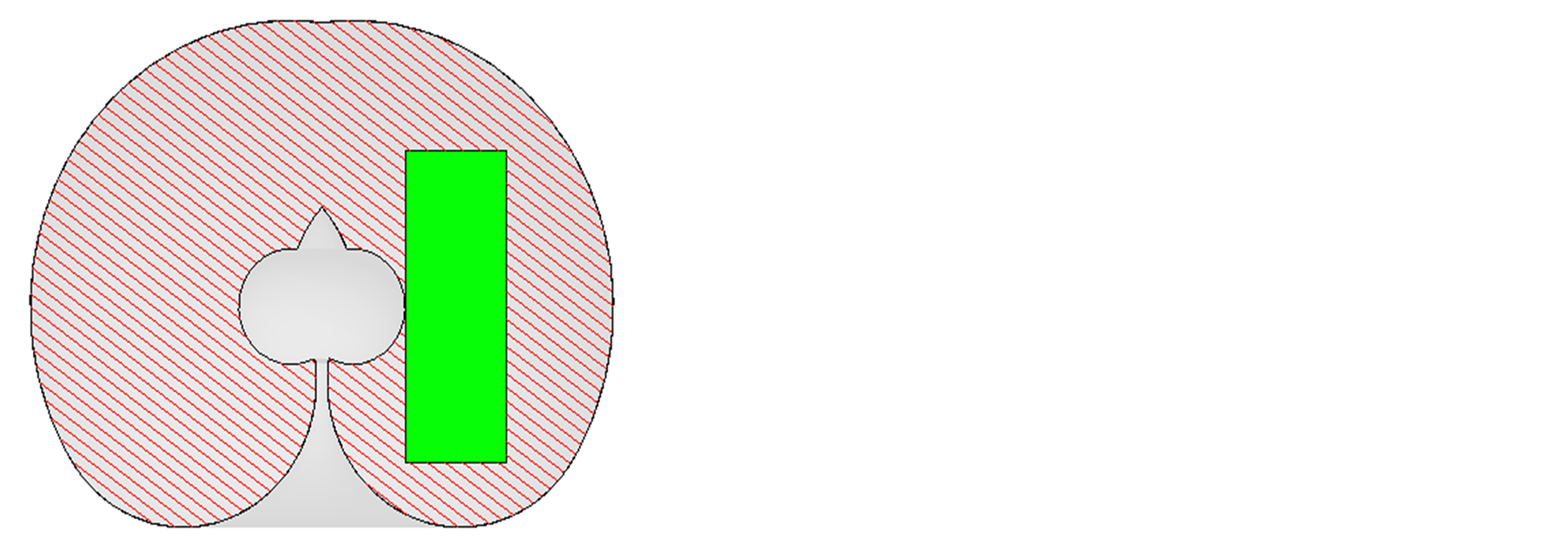
Figure 12. The section of the optimized workspace on surface D.

Figure 13. The optimized robot.
Table 3. The optimal solution.
With the prescribed workspace, the D-H parameters were optimized with GA to achieve the optimized solution meeting the constraining. The workspace and the prescribed workspace were modeled with Pro/E to prove the rationality of optimization result.
Acknowledgment
Project was supported by the National Natural Science Foundation of China (No. 51375314).
References
- Alciatore, D. and Ng, C. (1994) Determining Manipulator Workspace Boundaries Using the Monte Carlo Method and Least Squares Segmentation. ASME Robotics: Kinematics, Dynamics and Control, 72, 141-146.
- Zhang, L.J., Niu, Y.W. and Li, Y.Q. (2009) Research on Workspace of a Spherical 2-DOF Parallel Manipulator with Actuation Redundancy. China Mechanical Engineering, 20, 2974-2978.
- Xie, J., Kuang, L.H. and Ma, L.Z. (2011) Type Synthesis and Analysis of Workspace of a Novel Series Chinese Medical Massage Arm. China Mechanical Engineering, 22, 697-701.
- Chen, Z.L., Chen, X.S. and Xie, T. (2002) The Synthesis of Spatial Parallel Manipulators for a Specific Workspace with a Genetic Algorithm. China Mechanical Engineering, 13, 187-190.
- Laribi, M.A., Romdhane, L. and Zeghloul, S. (2007) Analysis and Dimensional Synthesis of the DELTA Robot for a Prescribed Workspace. Mechanism and Machine Theory, 42, 859-870.http://dx.doi.org/10.1016/j.mechmachtheory.2006.06.012
- Bi, Z.M., Wu, R.M. and Cai, H.G. (1994) Workspace Synthesis of Industrial Robot. Robot, 16, 181-184.
- Chablat, D., Moroz, G., Arakelian, V., et al. (2012) Solution Regions in the Parameter Space of a 3-RRR Decoupled Robot for a Prescribed Workspace. In: Latest Advances in Robot Kinematics, Springer Netherlands.
- Yi, G. and Wang, J.L. (2013) Studies on Information States Measurement for Modeling Design. Applied Mathematics Information Sciences, 7, 627-632. http://dx.doi.org/10.12785/amis/070228
- Zhan, X.L., Xin, H.B. and Lente, H.-P. (2010) Kinematics Simulation of MOTOMAN-HP3 Robot Based on Virtual Reality. China Mechanical Engineering, 21, 1952-1954.
- Zhang, P.C. and Zhang, Y. (2010) Study on Workspace Analysis of 6R Robot Based on Envelope Method. Machinery Design & Manufacture, 10, 164-166.
- Duan, Q.J., Huang, D.G. and Li S.N. (1996) The Graphic Methods of Robot Workspace and Inscribed Cube. Journal of Nan Jing University of Science and Technology, 20, 318-321.
- Xiao, Z.Q. and Cui, L.L. (2006) GA Based Concurrent Optimization and Design of Flexible Manipulator System. Robot, 26, 170-175.
- Xie, F., Chen, L.M. and Zhang, C.Y. (2008) Solution Joint Robot Workspace Based on Pro/E. Machine Tool & Hydraulics, 36, 145-146.
NOTES

*Corresponding author.