Modern Mechanical Engineering
Vol.4 No.1(2014), Article ID:43267,11 pages DOI:10.4236/mme.2014.41005
Stress Analysis of Bolted Joints Part I. Numerical Dimensioning Method
Department of Machine and Product Design, Budapest University of Technology and Economics, Budapest, Hungary Email: varadik@eik.bme.hu
Email: varadik@eik.bme.hu
Copyright (c) 2014 László Molnár et al. This is an open access article distributed under the Creative Commons Attribution License, which permits unrestricted use, distribution, and reproduction in any medium, provided the original work is properly cited. In accor-dance of the Creative Commons Attribution License all Copyrights (c) 2014 are reserved for SCIRP and the owner of the intellectual property László Molnár et al. All Copyright (c) 2014 are guarded by law and by SCIRP as a guardian.
Received November 4, 2013; revised December 21, 2013; accepted January 14, 2014
Keywords: Bolted Joints; Numerical Modeling; FE; Stress Analysis
ABSTRACT
For up-to-date bolted joints, first of all in vehicles, high strength bolts of 10.9 or even 12.9 are used, which are pre-tightened up to 90% or even 100% of the yield strength. The primary aim of this high degree utilization is the weight reduction. For the analytic dimensioning of bolted joints, the VDI 2230 Richtlinien German standard provides support. However, the analytic model can mostly consider the true structural characteristics only in a limited way. The analytic modeling is especially uncertain in case of multiple bolted joints when the load distri-bution among the bolts depends reasonably upon the elastic deformation of the participating elements in the joints over the geometry of the bolted joint. The first part of this paper deals with the problems of numerical modeling and stress analysis, respectively specifying the analytic dimensioning procedure by applying elastic or rather elastic-plastic material law. The error magnitude in bolted joint calculation was examined in case of omitting the existing threaded connectionbetween the bolt and the nutin order to simplify the model. The second part of the paper deals with the dimensioning of stands and cantilevers’ multi-bolt fixing problems, first of all, with the load distribution among the bolts keeping in view the analysis of the local slipping relations. For demonstrating the above technique, an elaborated numeric procedure is presented for a four-bolted cantilever, having bolted joints pre-tightened to the yield strength.
1. Introduction
The safe operation of industrial equipments is principally determined by the applied bolted joints which are pretightened up to 90% or even 100% of the material yield strength. As a consequence, the bolt, the nut and the elements encircled between (in case washers as well) take the pre-load (stress) according to the force system equilibrium. In the joining elements, this force equilibrium determines the stress and the deformation states mostly in the elastic but in cases of the plastic range.
The related references introduce the bolted joint according to numerous aspects (ex. [1]), or introduce the bolted joint behavior in a specific way (ex. [2,3]) that is a force system in equilibrium and the elastic displacements in a more or less simplified way. The finite element method can produce more reliable results by giving more accurate geometry, loading model and boundary conditions, furthermore by applying elastic or non-linear material laws.
In the first part of the study, a finite element model was created applicable for calculating the pre-tightening and loosening of bolted joints. By this model, bolted joint mechanic behaviors were studied in cases of different geometry and loading conditions. The numeric results were comparable to the analytic calculations, and useful conclusions could be drawn relating to certain calculation models.
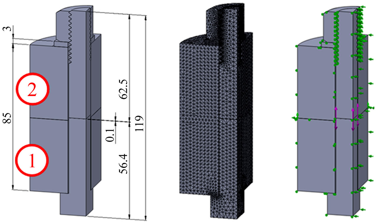
2. Studied Bolted Joints
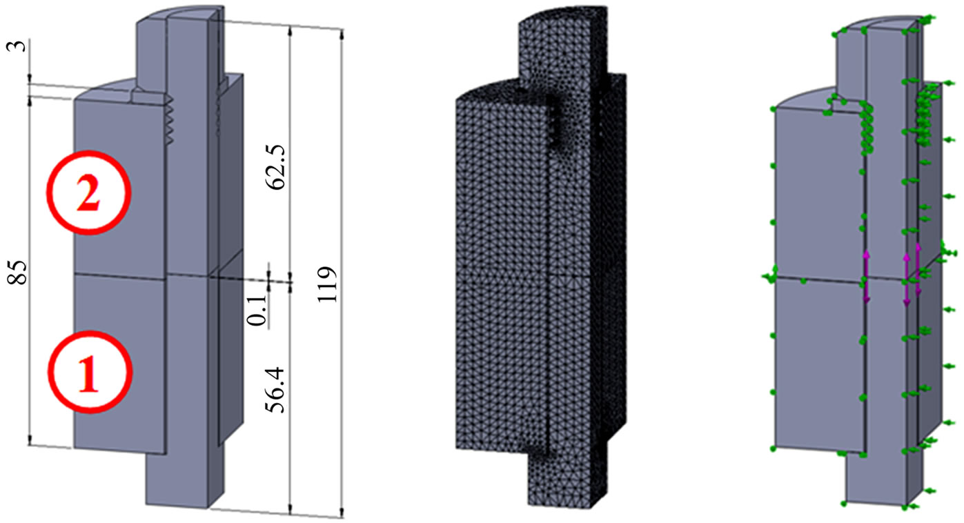
In this paper one M20 and one M24 bolted joints were studied. The geometric model of the bolted joints is shown in Figure 1. The geometric characteristics of bolt

Figure 1. Geometric model of the studied bolted joints.
threads are shown in Table 1 [4], while the bolted joint geometric and mechanic characteristics are summarized in Table 2.
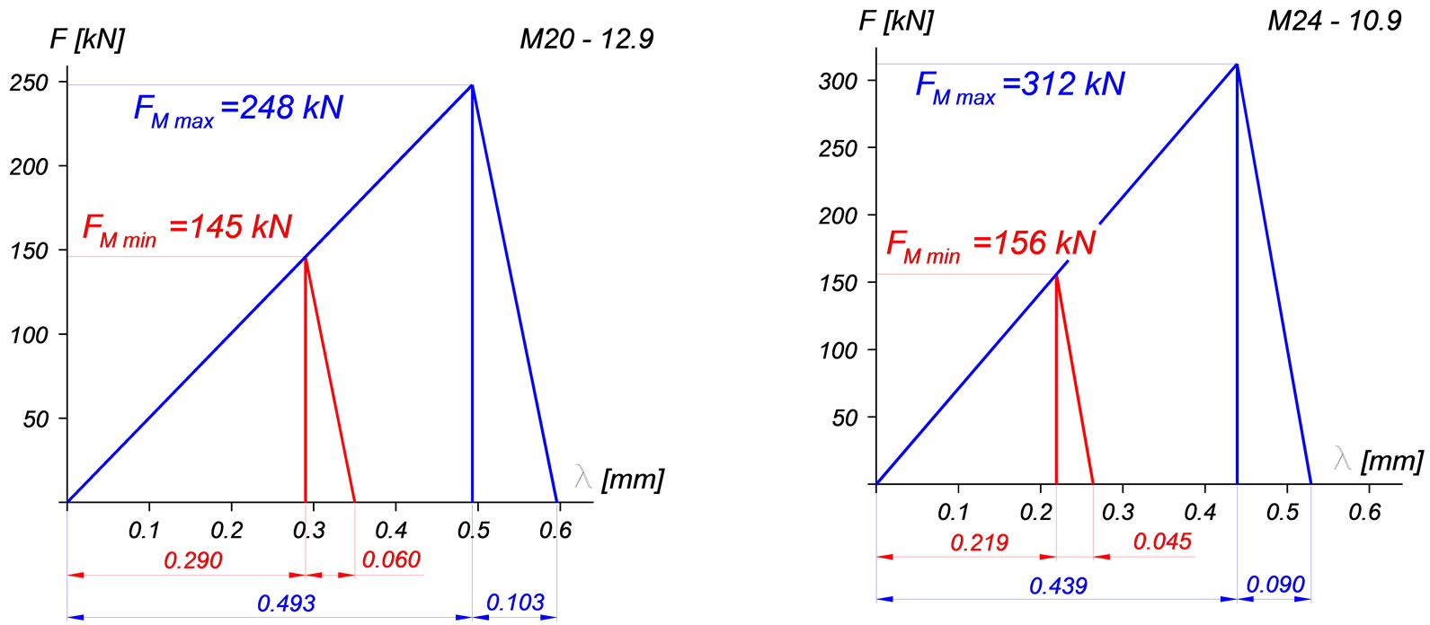
For M20 and M24 bolts the pre-tightening forces and the tightening torques were determined for 100% yield strength condition of the bolts in accordance with the recommendations of the VDI 2230 Richtlinien [5] (Table 3). In the table, row 8 provides loadings for the calculation related to the loosening of the loading model, while row 9 and 10 provide loads for the stress calculation of the joint.
The behavior of bolted joint used to be analyzed in force-deformation diagram. With the knowledge of the
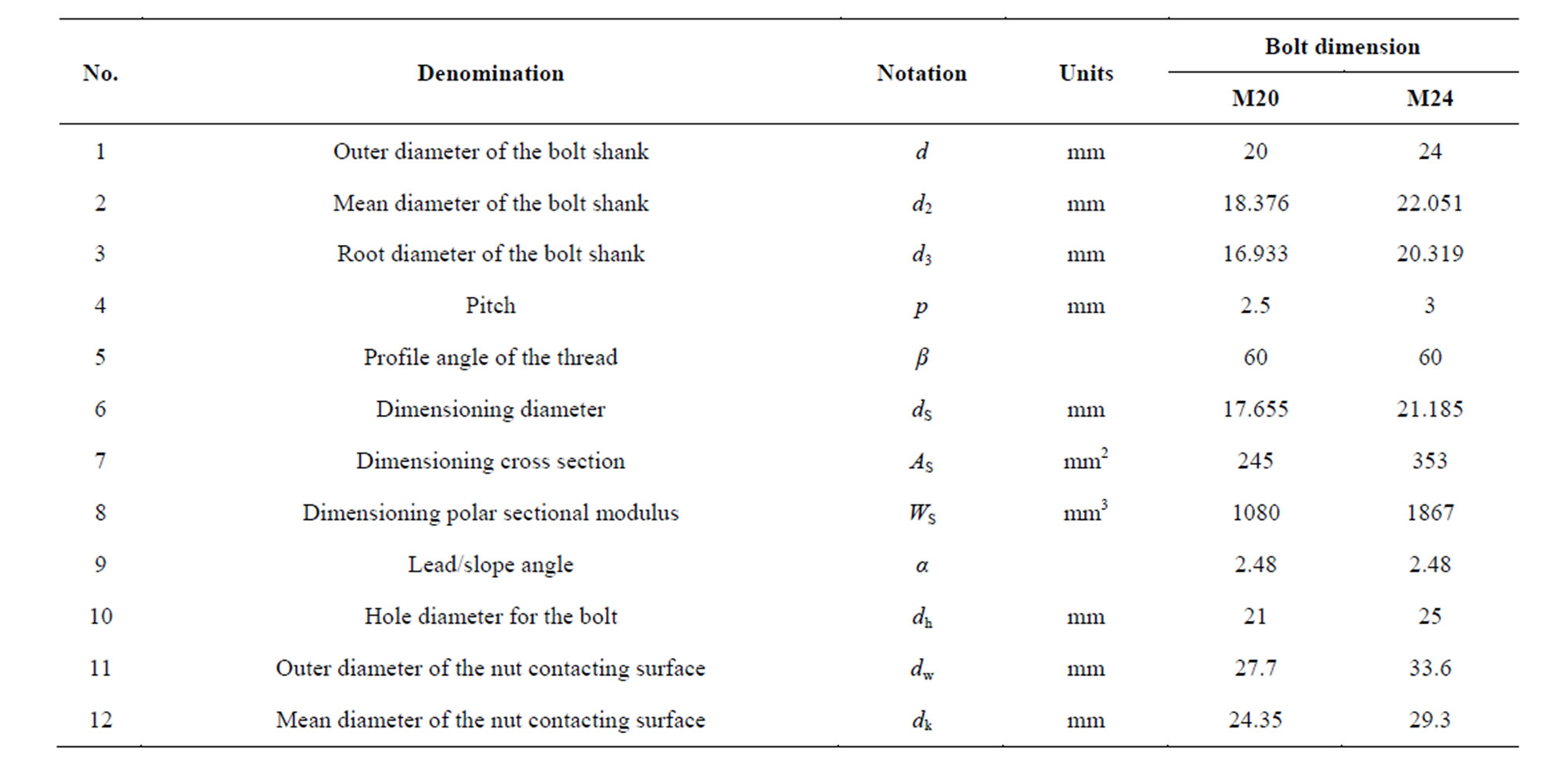
Table 1. Geometric data of bolt (and nut) threads.
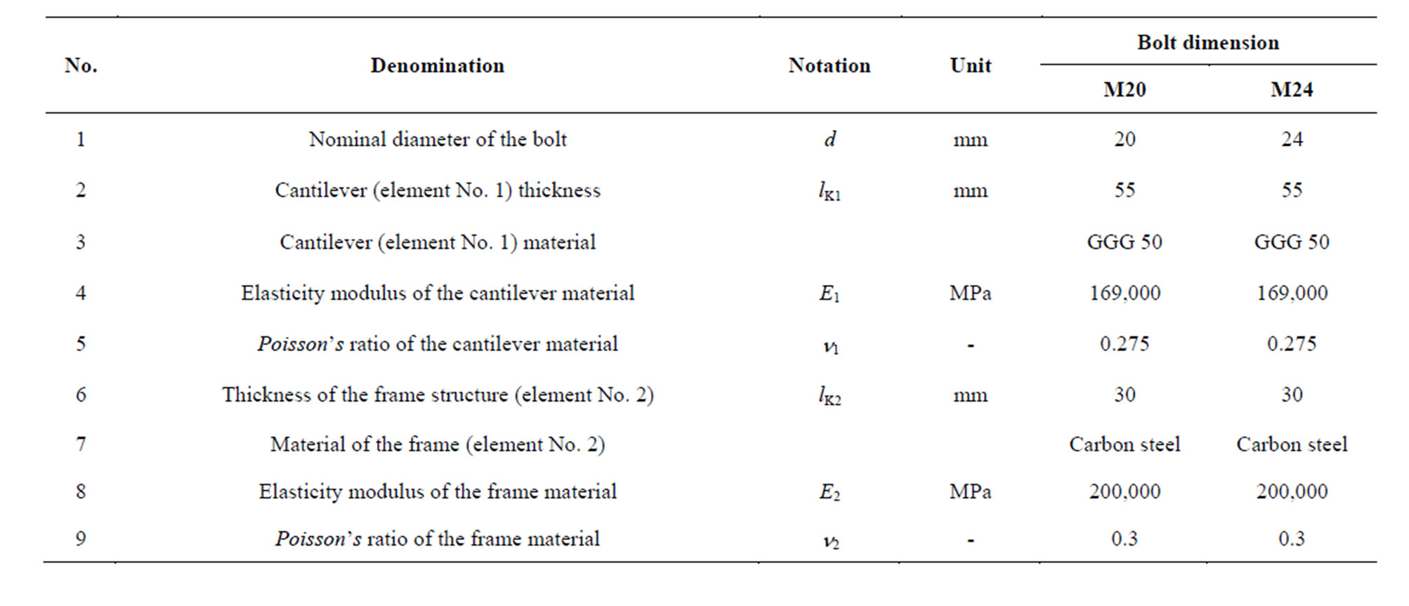
Table 2. Geometric and mechanic characteristics of the studied bolted joint.
geometric and mechanic characteristics of bolted joint’ elements the data for constructing the force-deformation diagram were determined. Based on the data summarized in Table 4 the force-deformation diagram is presented in Figure 2.
3. Finite Element Model of a Bolted Joint
The geometric model used for the numeric analysis is shown in Figure 3. The hexagonal head of the bolt and the nut were modeled by cylindrical body. For the connection of the bolt and the nut 6 contacting threads were considered and 5 more non contacting threads were on the bolt shank. While modeling the bolt in pre-tightened state 0.1 mm wide gap was formed in the bolt shank in the middle of the encircled elements 1 and 2. It was possible here to pre-tighten the joint by given force or displacement.
The connection between the bolt and the nut was studied in case of real threaded or simplified bonded connection cases. In case of threaded joint the FE model resulted large element numbers. In the case of bonded model (there is a bonded connection between the cylindrical surfaces of the bolt and the nut) this solution results reasonably reduced element numbers because of ignoring the real frictional contact behaviour.
The mechanical behavior of the highly loaded bolted joints may be influenced by the possible yielding of the structural elements included in the joint. Therefore calculations were carried out with linear elastic material law and with non-linear material law as well.
Table 5 summarizes the reviewed studies published in this paper. The numbers in the last columns refer to the paragraph numbers of this paper.
Table 6 summarizes the loading and the mechanical characteristics of bolted joints examined numerically.
4. Bolted Joint with Linear Material Law— Threaded Model
In case of M20 bolted joint, the compressed plate is a 65 mm cylindrical body having a 21 mm hole in the mid-
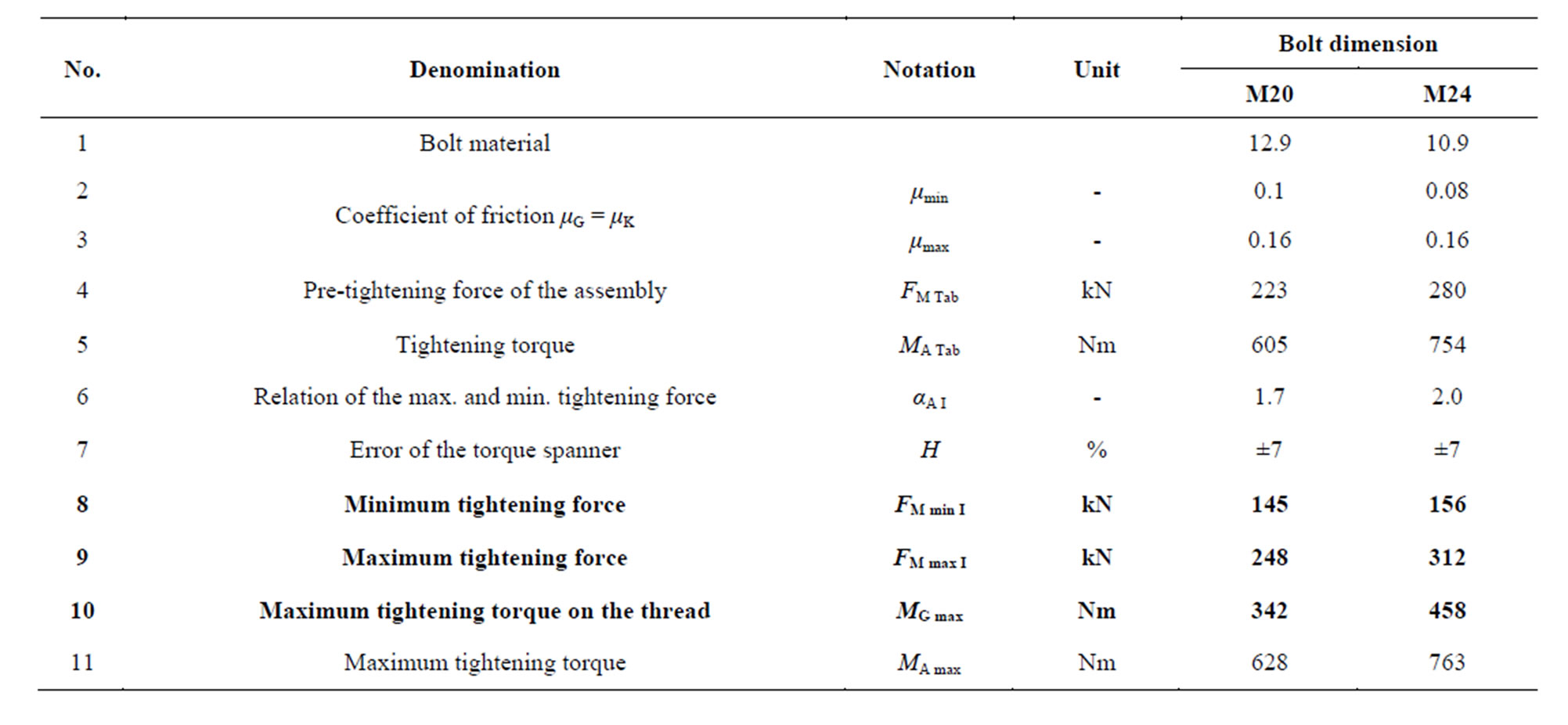
Table 3. Pre-tightening forces and pre-tightening torques.
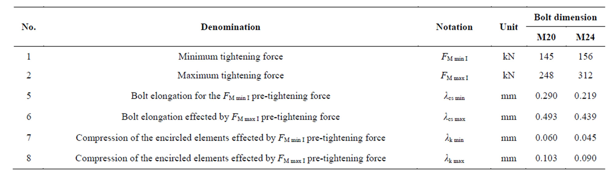
Table 4. Data for constructing (plotting) the force-deformation diagram.
 (a) (b)
Figure 2. Force-deformation diagrams of the pre-tightened bolted joint studied. (a) M20 bolt’s material: 12.9; (b) M24 bolt’s material: 10.9.
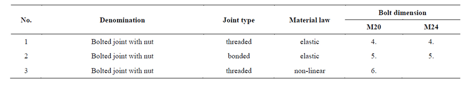
Table 5. Characteristics of the bolted joints studied.
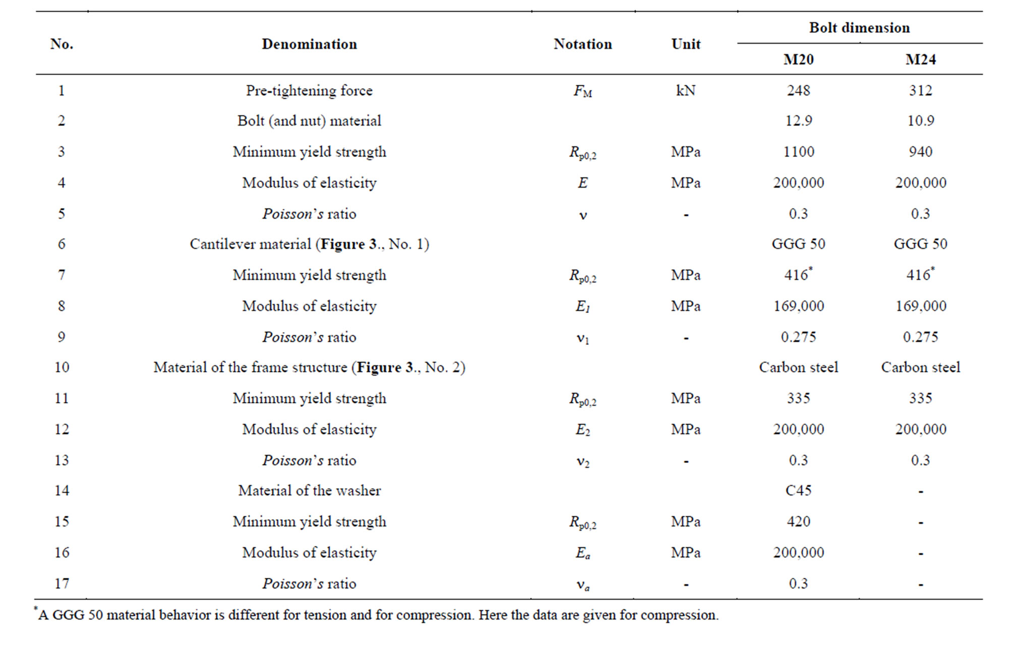
Table 6. Loading data and mechanical characteristics of bolted joints.
dle and for M24 bolt the compressed plate is a 120 mm cylindrical body having a 25 mm hole in the middle of the body. The dimensions, the FE model for its quarter, the loading and the boundary conditions are shown in Table 4 for M20 bolted joint.
Main characteristics of the finite element model are:
• type of the applied element: tetra 10;
• average element size: 2 mm;
• average element size in the threaded connection: 0.4 mm;
• average element size in the plate-bolt connection: 0.7 mm;
• number of elements: 193,009;
• number of nodes: 288,660.
The bolts are pre-tightened up to the yield strength, consequently the loading of the quarter model is 64 kN, which force applied on the bolt model upward and downwards on the surfaces (Figure 4(c)) provided by the separation gap.
The coefficient of friction on the threads is μ = 0.1. It should be noted that the shearing loading resulted by the tightening torque of the nut is not considered by the model.
Utilizing the symmetric characteristics of the model the displacements of side surfaces¾perpendicular to the
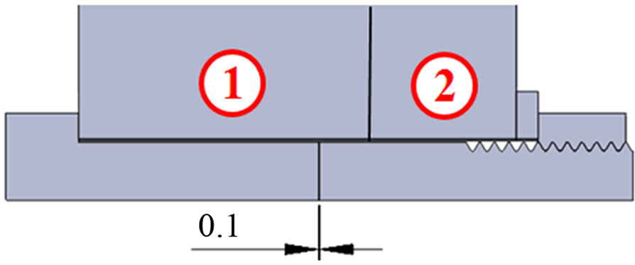
Figure 3. Geometric model of the bolted joint.
surface¾must be prevented. This is ensured by fixing the edge of the plate bigger diameter of the model (in spatial position, see in Figure 4(c)). The contact surfaces have everywhere Node-to-surface type contact. Due to the quarter symmetry assumed, the slope angle of the threaded connections was ignored.
The z direction displacement field is shown in Figure 5. The sum of the bolt elongation and the compression of the encircled elements can be red directly from the figure:
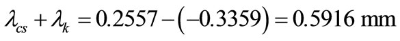 (1)
(1)
The elastic deformations were determined by the displacement averages of the nodes on surfaces 1 and 2 and on surfaces 3 and 4 (Figure 5).
In Figure 6, the von Mieses equivalent stresses were presented in such a way that the upper limit of scale is maximized in 1100 MPa. In this way those fields can be seen well where the stress is near or even over of the yield strength in the bolt and in the nut. The right side figure shows the nut and the surroundings of the bolt head enlarged. The stress concentration of the threads and the head-shank transition can be seen in the figure.
When the stress image is cut off by the yield strength of the washer (420 MPa) those zones can be seen by red, where the washer is already in the elastic-plastic zone (Figure 7). The washer reaches the yield strength in the whole volume under the nut. At this stress level both the bolt and the nut are in the elastic range (see Figure 6).
By getting down (querying) the displacements it is possible to determine the sum of the bolt elastic elongation and the encircled elements compression and it makes possible to construct the pre-tightening force-deformation diagram (Figure 8). In the figure, the blue triangle is the analytic and the red is the numeric calculation re-
 (a) (b) (c)
Figure 4. Studied threaded bolted joints (a) dimensions; (b) FE model, (c) Loading and boundary conditions. (1) Cantilever (GGG 50), (2) Frame structure (structural steel).
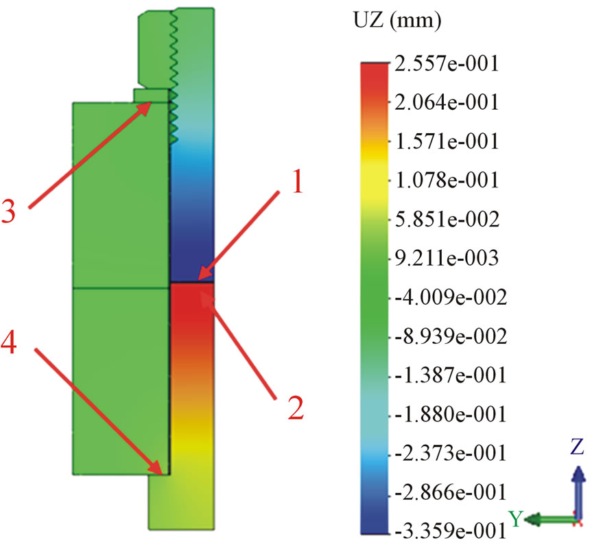
Figure 5. The calculated displacement field in z direction. The greatest displacement is 0.2557 mm, while the smallest displacement is 0.3359 mm.
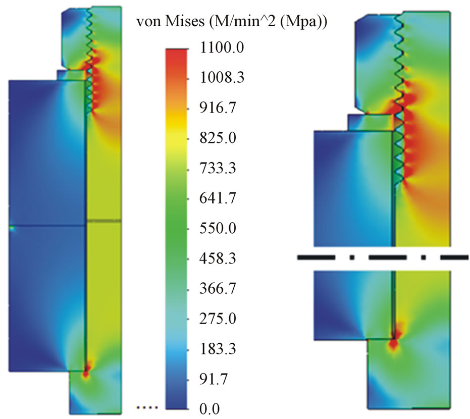
Figure 6. Von Mises equivalent stresses in the bolted joint (complete model and enlarged detail). The maximum of stress scale was set to 1100 MPa.
sults. It can be seen that the threaded model reflects well the analytic result.
Similarly to the earlier analysis the calculation related to M24 bolted joint was executed too. The results obtained from the calculation provide the force-deformation diagram shown in Figure 9.
5. Bolted Joint with Linear Elastic Material Law—bonded Model
The bonded model differs from the model examined—in the earlier paragraph—in such a way that the threaded connection is not formed between the nut and the bolt. In the place of the threaded joint cylindrical surfaces are
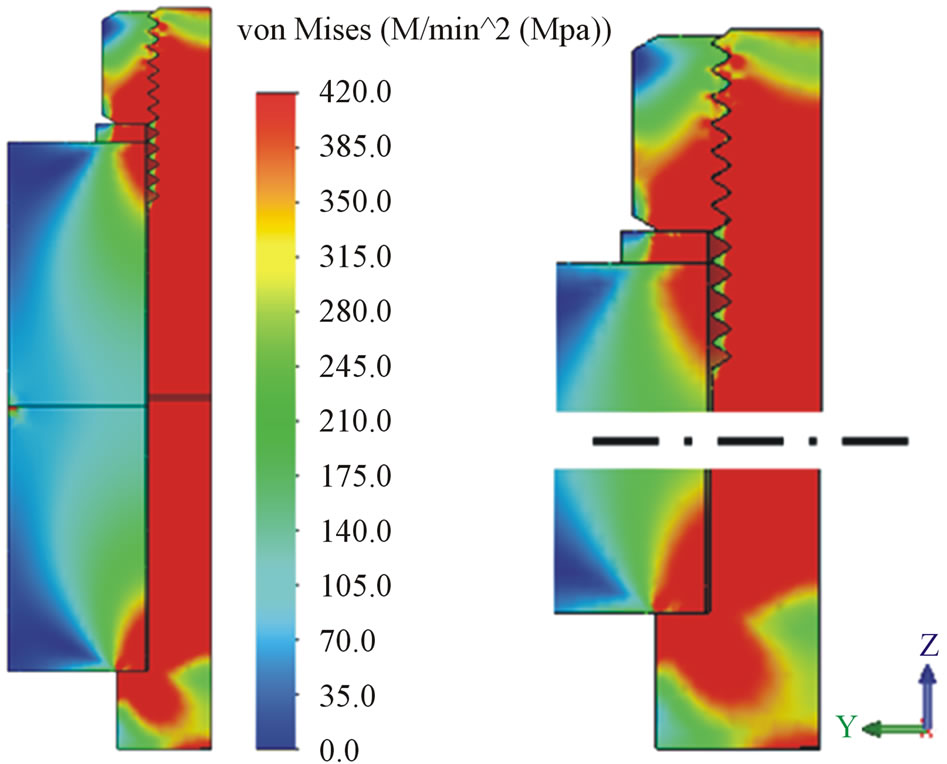
Figure 7. Equivalent stresses in the bolted joint. The stress scale maximum was set to 420 MPa.
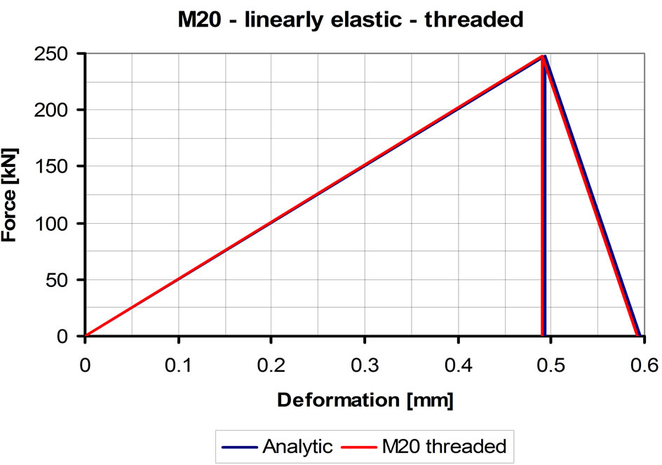
Figure 8. Force-deformation diagram of M20 bolted joint. Threaded model, linear elastic material law.
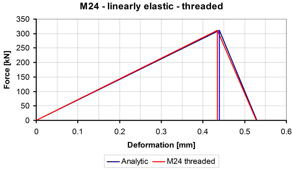
Figure 9. Force-deformation diagram of M24 bolted joint, threaded model using linear elastic material law.
formed having the diameter equal to the mean thread diameter and defining bonded joint between the two parts. The aim of this study is to estimate the resulted error magnitude of this approximation yielding to a smaller FE model, with less elements (This model takes into consideration the elastic deformation of the bolt shank and the compressed elements, but neglects the elastic behavior of the thread surroundings).
The geometry, the dimensions, FE quarter model, the loading and the boundary conditions for M20 bolted joint are shown in Figure 10.
Main characteristics of the finite element model:
• type of the applied element: tetra 10;
• average element size: 2 mm;
• average element size in the threaded connection: 0.4 mm;
• average element size in the plate-bolt connection: 0.7 mm;
• number of elements: 114,752;
• number of nodes: 170,660.
The loading of the model and the boundary conditions are the same as given in the previous paragraph.
The calculated z direction displacement field is shown in Figure 11. The sum of the bolt elongation and the encircled element compression can be determined from the figure:
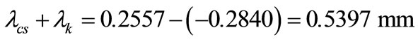 (2)
(2)
In Figure 12, the equivalent von Mieses stresses were presented in such a way that the scale upper limit was maximized in 1100 MPa. In this way, those fields can be seen by red where the stress is near or even over the yield strength in the bolt and in the nut. The right side figure shows the nut and the surroundings of the bolt head enlarged. The stress concentration of the threads and the head-shank transition can be seen in the figure. However, the stresses in the surrounding of the bonded connection are reasonably reduced comparing to the threaded joint.
The bonded model force-deformation diagram is shown in green color in Figure 13. In the figure, the blue ilustrates the analytic and the red shows the numeric calculation result. The bonded model is more rigid comparing to the threaded model. Here the complete elastic deformation is about 9% smaller than in the case of the threaded model.
Similarly to the earlier study the related calculations were carried out for M24 bolted joints too. The calculation resulted force-deformation diagram is shown in Figure 14.
Based on the already completed studies it can be stated that the results of threaded finite element model answers to bolt dimensioning procedure of the VDI 2230 Richtlinien. The simplified bonded model increases the rigidity of the joint by 9%. The differences in the rigidity of the two models are resulted by the limited expansion¾in radial direction¾of the bonded joint, as the contact behavior between the threads are not considered here (Figure 15).
6. Bolted Joint with Non-Linear Materal Law—Threaded Model
The studies carried out with linear material law¾in the previous two paragraphs¾pointed out that the stresses in the bolted joints reach and even exceed the yield strength in more components of the bolted joints. This made necessary the non-linear analysis. The concerned numerical model is shown in Figure 16.
In order to reduce the CPU time¾utilizing the approach of circular symmetry¾1/24-th of the model was examined (studied). The characteristics of the model are:
• applied element type: tetra 10;
• average element size: 2 mm;
• average element size at the thread: 0.4 mm;
• average element size in the plate-bolt connection: 0.7 mm;
 (a) (b) (c)
Figure 10. The studied bonded bolted joint (a) dimensions; (b) FE model, (c) Loading and boundary condition. (1) Cantilever (GGG 50), (2) Frame structure (structural steel).
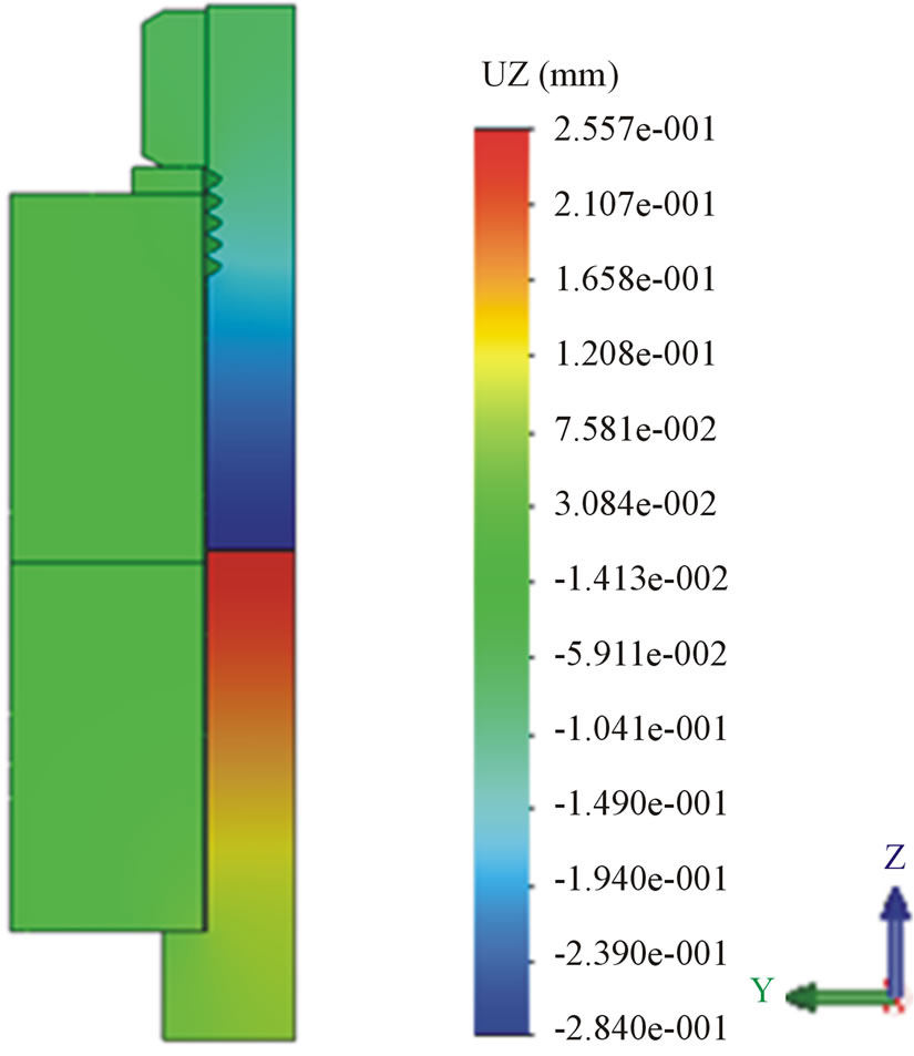
Figure 11. The calculated displacement in z direction. The maximum displacement is: 0.2557 mm and the minimum displacement is: −0.2840 mm.
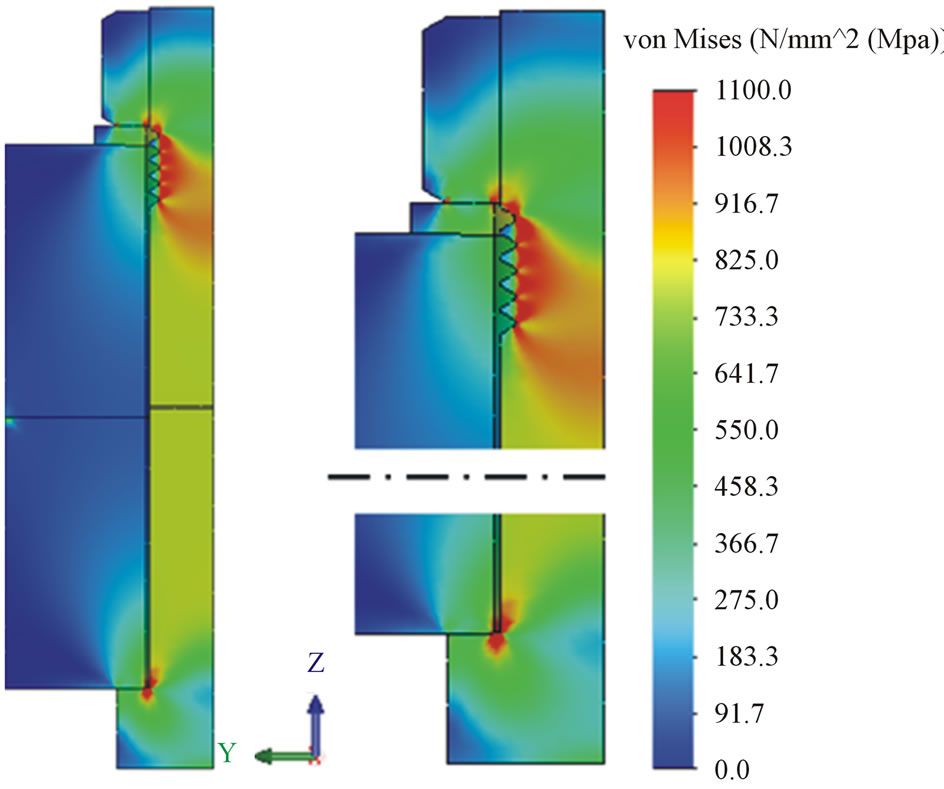
Figure 12. Equivalent stresses in the bolted joint. The stress scale maximum was set to 1100 MPa.
• number of elements: 32,557;
• number of nodes: 54,628.
The bolt is pre-stressed¾up to the yield strength¾and 10.3 kN answers to the loading for the 1/24 (size) of the model.
The boundary conditions coincide to the boundary conditions written in the previous paragraph.
Over the yield strength the real behavior of the material applied is not known therefore the study was carried out with assumed material law. During the intake of the material law the gradient of the hardening part is determined in such a way that the stress level should reach the
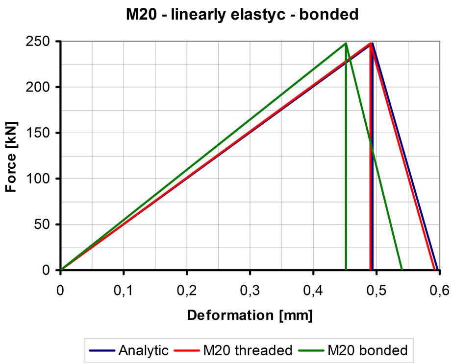
Figure 13. The force-deformation diagram of the M20 bolt. Bonded model with linear elastic material law.
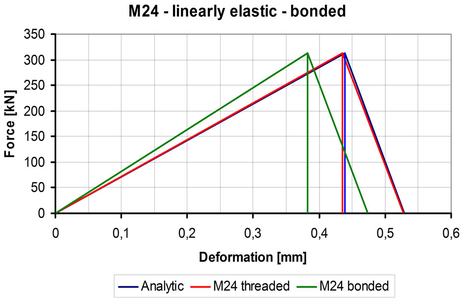
Figure 14. Force-deformation diagram of M24 bolt. Bonded model with linear elastic material law.
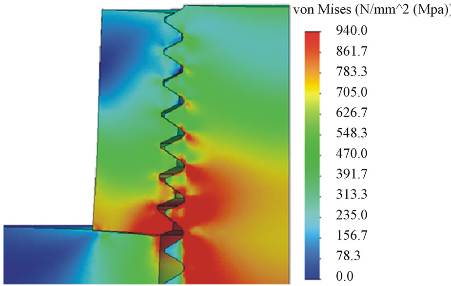
Figure 15. M24 bolt, threaded model. As an effect of the load the nut expands in radial direction. Scaling of deformation is: 10.
ultimate strength at the tensile break strain.
Besides, the transition was made continuous between the elastic and plastic sections. The description of the assumed material law is summarized in Table 7 and shown in Figure 17.
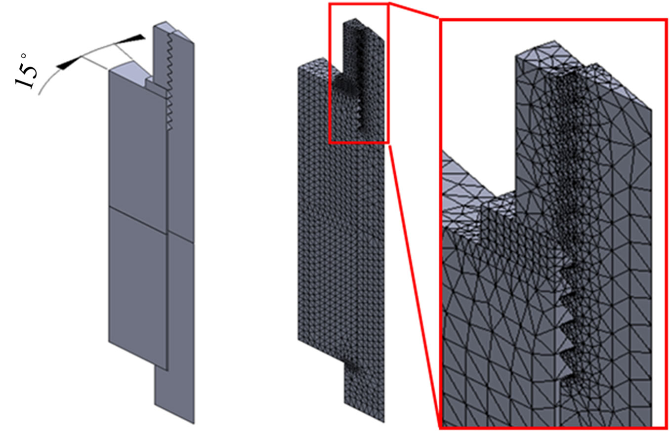
Figure 16. Numeric model for the non-linear examination.
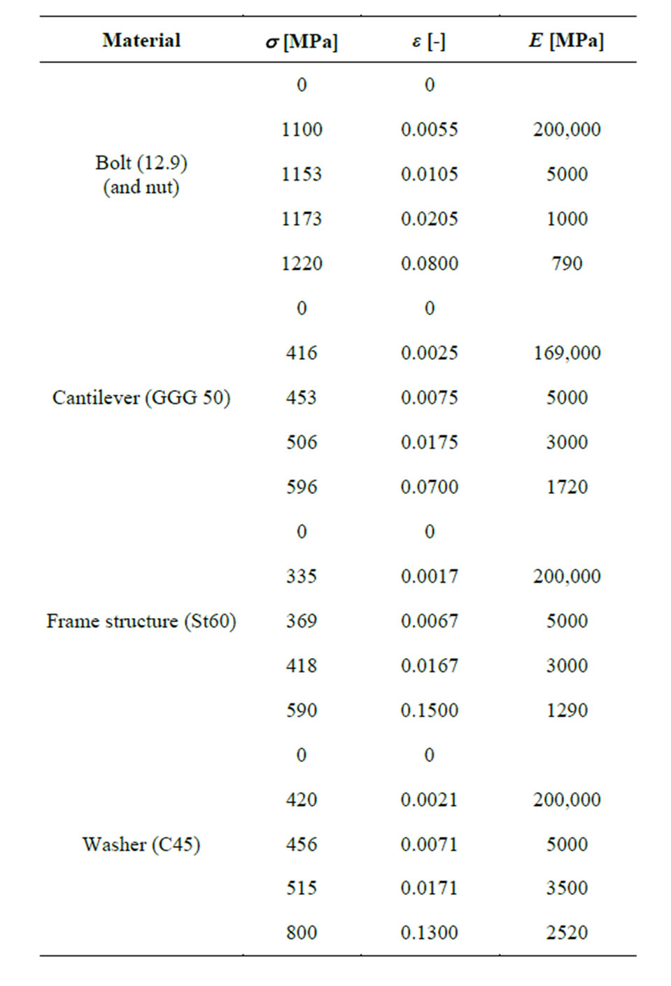
Table 7. The characteristic points of the material law.
The calculated equivalent strains are illustrated in Figure 18, where the equivalent strain values are found
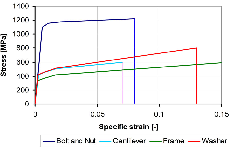
Figure 17. Applied material law with strain hardening features.
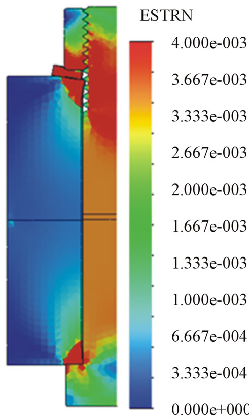
Figure 18. Equivalent specific strain. The maximum of the strain scale was set to 0.004. The deformation scale is 1:1.
in the range of 0 - 0.004. The strains were drawn in the deformed form of the joints by using deformation scale 1:1. Under the bolt head and washer substantial magnitude of deformation of the washer and the encircled elements can be seen well in the figures.
From z directional displacements the sum of the bolt elongation and compression of the encircled elements:
 (3)
(3)
This considerable magnitude of elongation can be explained by the applied structural elements having low yield strengths.
The force-deformation diagram of bolted joint calculated with modified material law is shown in Figure 19.
In Table 8, the biggest elongations and stresses¾developed in the structural elements of the bolted joints¾ were summarized. These are shown in Figure 20. In the case of the upper curve, the first symbol represents the bolt, while the second shows the nut behavior.
The calculations were carried out for the maximum pre-tightening force (FM max), which was obtained at the minimum friction coefficient and at the maximum tightening torque. However the probability is rather rare for these conditions. The non-linear calculations were car-
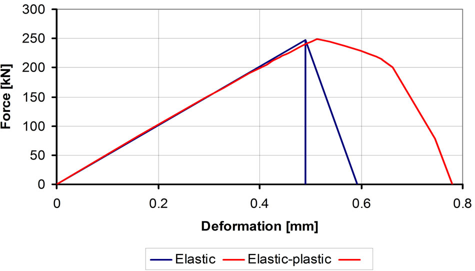
Figure 19. Force-deformation diagram of the modified nonlinear material law.
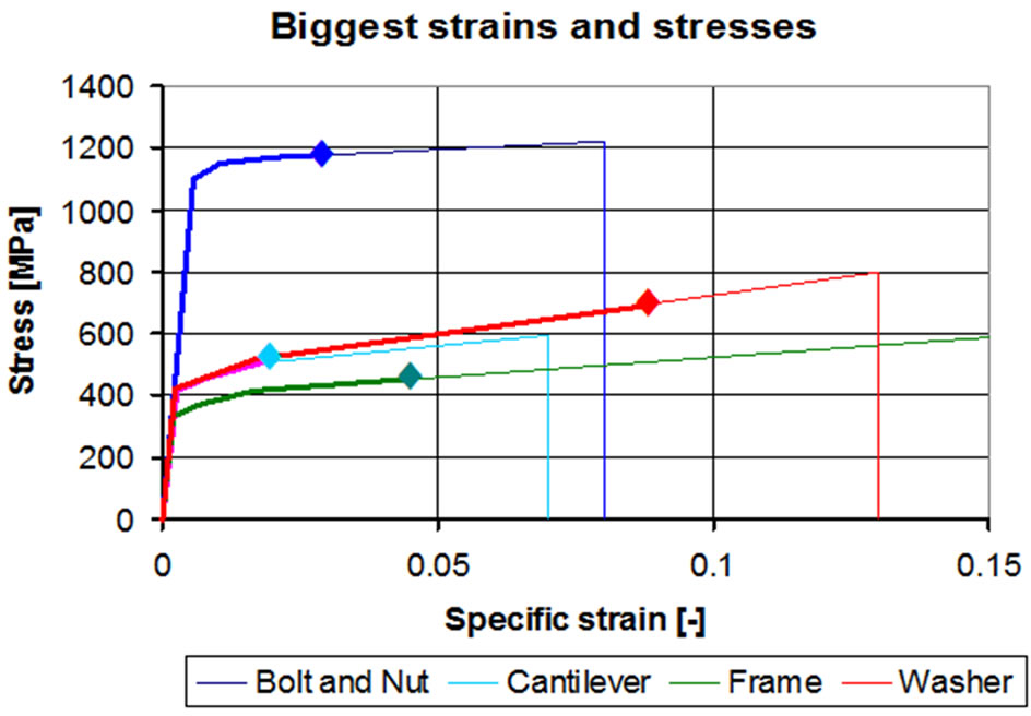
Figure 20. The largest stresses and deformations in the structural elements.
ried out for minimum (FMmin), and average (FMk) pretightening forces as well. These results are shown in Figure 21. It can be seen from the figure that small amount of plastic deformation may happen even at mean pre-tightening forces due to the excessive local stress concentrations. This last result represents the most frequent case.
6. Conclusions
In the first part of this paper, the pre-tightening behavior of the high strength (10.9 és 12.9) bolted joints was summarized. At first, the VDI Richtlinien calculation method and then the finite element analysis were used. The FE model is also applicable for analyzing the contact state of the threaded contact showing a good conformity to the calculations according to VDI. The simplified¾so called bonded¾model shows 9% more rigid behavior due to the simplified surrounding contact.
The FEA model¾analyzing the elastic-plastic behavior¾demonstrates the smaller extent plastic behavior effect of the cantilever, the frame structure and also the washer. The bigger deformations obtained are the consequence of the smaller yield strength compared to the 90% - 100% pre-tightened bolt shank. Above all, it can be stated that during the stress analysis of pre-stressed high strength bolted joints, the expected elastic-plastic defor-
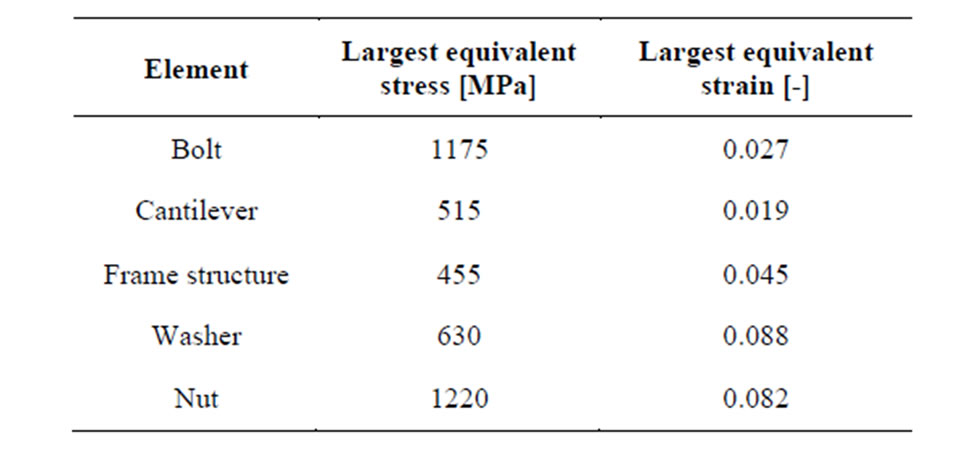
Table 8. The largest equivalent stresses and strains.
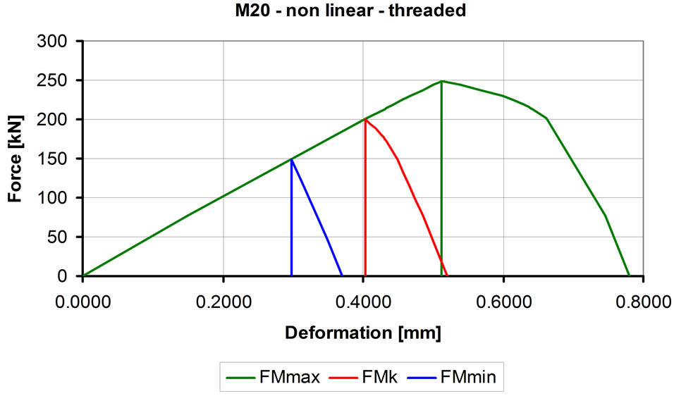
Figure 21. The calculated force-deformation diagrams for non-linear model at the minimum, the mean and the maximum pre-tightening force.
mations of the same elements of the joints must be considered, too.
REFERENCES
- J. H. Bickford, “An Introduction to the Design and Behavior of Bolted Joints,” Mechanical Engineering Marcel Dekker, Inc., 1990, New York.
- J. M. Mínguez and J. Vogwell, “Theoretical Analysis of Preloaded Bolted Joints Subjected to Cyclic Loading,” International Journal of Mechanical Engineering Education, Vol. 33, No. 4, 2005, pp. 349-357.
- O. Zhang, “Discussions on Behavior of Bolted Joints in Tension,” Transactions of the ASME Journal of Mechanical Design, Vol. 127, 2005, pp. 506-510.
- DIN ISO 262. ISO general purpose metric screw treads —Selected sizes for screws, bolts and nuts, ISO 262, 1998.
- Systematische Berechnung hochbeanspruchter Schraubenverbindungen Zylindrische Einschraubenverbindungen. VDI-Richtlinien, VDI 2230, 2003.