Modern Mechanical Engineering
Vol. 2 No. 4 (2012) , Article ID: 25134 , 8 pages DOI:10.4236/mme.2012.24019
Evaluation of Residual Stresses Induced by High Speed Milling Using an Indentation Method
1Departamento de Ingeniería Electromecánica—Departamento de Ingeniería Industrial, Facultad Regional Rafaela, Universidad Tecnológica Nacional, Rafaela, Argentina
2División Metrología Dimensional, Centro Regional Rosario (INTI), Rosario, Argentina
Email: *felipe.diaz@frra.utn.edu.ar
Received August 19, 2012; revised September 26, 2012; accepted October 4, 2012
Keywords: Residual Stresses; High Speed Milling; Indentation Methods; Aluminium Alloys; Principal Directions
ABSTRACT
In this work, a recently developed method based on the change of distance between collinear indents is used to evaluate different states of residual stress, which were generated in samples of AA 6082-T6 and AA 7075-T6 aluminium alloys milled at high speed. One of the advantages of this method, which needs a universal measuring machine, is not requiring neither the use of specific equipment nor highly skilled operators. Also, by integrating an indentation device to the mentioned machine, the absolute error of measurement can be reduced. In results obtained in samples subjected to different cutting conditions it is observed a correlation between the stress values and the depth of cut, showing the AA 6082-T6 alloy higher susceptibility to be stressed. Furthermore, the high sensitivity of the method allowed detecting very small differences in the values reached by different normal components in the zones corresponding to climb and conventional cutting. It is important to note that these differences were similar for both evaluated alloys. Finally, the directions associated with the principal components of residual stress, where maximum local plastic stretching occurs, were found to be strongly dependent on the rolling direction prior to machining.
1. Introduction
During machining of a mechanical component, the residual stresses are introduced by both local plastic deformation generated by the interaction with the cutting tool, and the heat conducted from the primary deformation zone toward the surface [1,2]. In turn, both the local plastic deformation and the heat conducted are dependent on the properties of the machined material as well as the process parameters, the geometry of the tool and cooling conditions. It is important to mention that a small variation in any of the selected parameters can change substantially the level and/or the sign of the residual stress distribution. Therefore, it is important to determine these levels and signs in order to know if the machined component has been strengthened or weakened on the surface.
The purpose of this study is to evaluate, in samples of AA 6082-T6 and AA 7075-T6 aluminium alloys milled at high speed, both the levels and the signs reached by different normal components of residual stress as well as the directions corresponding to the maximum levels. It must be noted that in most papers evaluating residual stress states generated by high speed milling, stress component analysis was carried out in one or two directions. Instead, in this work the analysis is extended to six normal components including those associated with radial and tangential cutting directions. In this way, it was possible to assess the influences of cutting and rolling directions on the residual stress introduction. The aforesaid normal components were obtained by using an indentation method previously optimized [3]. This method, which needs a universal measuring machine (UMM), allows to measure residual displacements with an absolute error much smaller than those corresponding to the traditional techniques [4]. By performing face milling operations with central cutting, it was possible to subdivide the generated surface in two adjacent zones of equivalent areas called the climb and conventional cutting zones [5]. Such milling operations were carried out in a numerically controlled vertical milling machine. The depth of cut was varied to evaluate how this change affects the levels and signs of the normal components. Finally, the centroids of the zones corresponding to climb and conventional cutting were independently analyzed to assess the accuracy and sensitivity of the indentation method to detect the directions where the mentioned normal components reach the maximum and minimum values.
2. Related Work
In recent decades, different experimental techniques have been developed, optimized, and adapted for the determination of residual stresses generated by different types of machining. Of these experimental techniques, two have been the most widely used and accepted for machined components: X-ray diffraction technique [6,7] and the hole-drilling method [8,9]. More recently, different indentation techniques have been used to determine residual stresses in machined parts. Regarding these techniques, Warren et al. [10] conducted a study of nanoindentation focused on understanding the basic relationships between mechanical behaviour, microstructure, and residual stresses introduced in machined components. Later on, Wyatt and Berry [11] developed a micro-indentation method that allows performing different studies of residual stresses in high-speed milled components.
Regarding studies about residual stresses generated by milling in aluminium alloys, Fuh and Wu [12] presented a mathematical model for predicting residual stresses caused by end milling in specimens of AA 2014-T6 alloy. The results obtained through this model were compared with experimental results derived using the hole-drilling technique. Then, Rao and Shin [13] carried out an analytical and experimental study in samples of AA 7075-T6 alloy milled with a single insert fly-cutter. In this work, high-speed cutting process mechanics is presented, and residual stresses were evaluated in function of different cutting parameters. It noteworthy that, in this case, the study of the residual stress left in the machined surface was limited to the tangential stress component in the cutting direction. Recently, Denkena and De Leon [14] studied the influence of cutting parameters and tool geometry on the level of residual stresses induced by milling in workpieces of forged aluminium alloys. More recently, Díaz et al. [15,16] and Mammana et. al. [17] studied the influence of thermal and mechanical effects in the generation of residual stresses in samples of different aluminium alloys milled at high speed, using an optimized indentation method.
It is very important to note that, in these last three studies, the residual stress components were determined from data obtained using a UMM, avoiding the use of specific equipment and personnel. In addition, for residual displacement measurements, the use of a measuring machine allows to significantly reduce the absolute error of measurement in relation to those corresponding to X-ray diffraction technique and the hole-drilling method (from ±25 MPa to ±0.9 MPa). Moreover, before the three aforementioned studies, the measuring machines, which are considered as highly sophisticated equipments, had not been evaluated to carry out measurements of residual displacements.
3. Materials and Cutting Procedure
The materials evaluated in this study were two rolled products 4 mm thick, corresponding to 6082-T6 and 7075-T6 aluminium alloys. These materials can be considered to have middle and high mechanical resistance, respectively. It must be noted that 6082-T6 is a relatively new alloy, which is used in structural applications in the marine and transportation industries as well as for machined precision parts in the automotive industry. On the other hand, 7075-T6 is a structural alloy widely used for aircraft, aerospace and defense applications due to its high mechanical resistance/weight ratio. The chemical composition and mechanical properties of these alloys are reported in Tables 1 and 2, respectively.
The maquinability of 6082-T6 and 7075-T6 aluminium alloys is good because their ratings are B and C, respectively. It should be noted that A, B, C, D and E are

Table 1. Chemical composition of the evaluated alloys.

Table 2. Mechanical properties of the evaluated alloys.
relative ratings—for aluminium alloys—in increasing order of chip length and decreasing order of quality of finish [18].
The dimensions of the samples were 110 mm × 40 mm × 4 mm. In the case of material 6082-T6, the longitudinal axis of samples matches the original direction of rolling. In contrast, in the case of material 7075-T6, the transversal direction corresponds with the rolling direction. Figure 1 shows a schematic drawing of how the specimens were cut from the original plates. Prior to machining tests, the samples were thermally treated to remove the residual stresses generated during the rolling operation. The temperature and time for this treatment were 300˚C and 80 minutes respectively. For machining tests, a face mill of 63 mm in diameter was used. Five tungsten carbide inserts (Palbit SEHT 1204 AFFN-AL SM10) were incorporated to this face mill. Table 3 shows both the geometry of the mentioned inserts and the process parameters selected for this study. The tests were carried out in a numerically controlled vertical milling machine (Clever CMM-100). An upper view of the relative position of the sample in relation to the cutting tool is shown in Figure 2.
4. Indentation Method
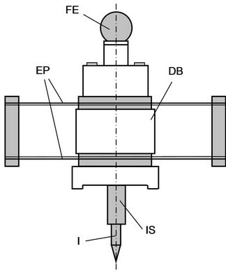
The present indentation method consists of introducing a series of spaced indents on the machined surface to be evaluated, for measuring, before and after a distension treatment, the indent coordinates using a UMM [11]. Then, different components of residual strain and stress can be obtained from these coordinates. In this work we used a special design indenter device that attaches to the main header of the measuring machine (GSIP MU-314), allowing greater accuracy in both the generation and the optical location of each indent. Figure 3(a) shows a front view of the device. The body of the device is made up of a system of thin elastic plates that enables to regulate the indentation load. This device is attached to an electronic sensor, which allows calibrating the depth of the indent
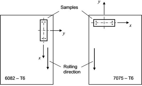
Figure 1. Rolling direction in samples.
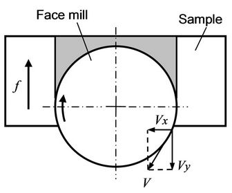
Figure 2. Upper view of the tool-sample system.
 (a)
(a)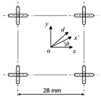 (b)
(b)
Figure 3. (a) Front view of the indentation device: (FE) fixation sphere, (DB) device body, (EP) elastic plates, (I) indentator, (IS) indentator support; (b) Distribution of elongated indents.
with high accuracy. By using this mechanical device it is possible to introduce elongated indents, which reduce the uncertainty associated with the repositioning of the samples after the distension treatment [15]. Figure 3(b) shows a distribution of elongated indents.

Table 3. Tool geometry and cutting conditions.
Although local residual stress fields are introduced by indentation, the errors generated by those fields can be minimized by a proper separation of the evaluated indents. In our case, the nominal distance between each indent pair was 28 mm, as shown in Figure 3(b). The indent coordinates were optically measured using a precision microscope, which is a primary accessory of a UMM. Figure 4 shows this accessory, from which it is possible to carry out the basic functions of magnification and referencing. Each indent position is strictly defined with respect to the optical axis of the microscope. For establishing the exact position of coincidence for reading the coordinates in auxiliary microscopes [16], the very high precision stage shown in Figure 4—on which the milled sample is mounted—must be carefully moved in predetermined directions. The staging plane contains two mutually perpendicular displacement axes, which can be considered to represent a system of orthogonal Cartesian axes. It is worth noting that any selected point on the observed surface can be brought into the reference position of the optical system, provided it is contained within the displacement ranges of the precision stage. In our particular case (MMU GSIP MU-314), the displacement ranges are 400 mm (x-axis) and 100 mm (y-axis). These ranges exceed the maximum nominal distances measured in the milled surfaces, which were 56 mm (x-axis) and 28 mm (y-axis).
It is important to mention that the coordinates of the indents were measured, before and after the distension treatment, within a temperature range of 20˚C ± 0.2˚C, with a variation rate less than 0.01˚C/min. With regard to the distension treatment, this was carried out for a period of 80 minutes at a temperature of 300˚C.
5. Determination of Residual Stress Components
By using the method of indent coordinate measurement it is possible to evaluate the stress state at any point of the milled surface. Taking into account a previous study [15], two significant points were chosen for this work. Figure 5 shows these points (A and B), which are located in the centroids of the climb and conventional cutting zones.
For each of these centroids it is possible to determine normal components of the residual strain in three directions. Two of these (corresponding to εx and εy) are perpendicular and in turn parallel to the sides of a square defined by indents, as shown in Figure 3(b). The remaining direction (associated to εd) corresponds to the
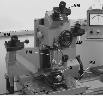
Figure 4. Picture of the used measuring machine: (PM) precision microscope, (S) sample, (PS) precision stage, (AM) auxiliary microscope.
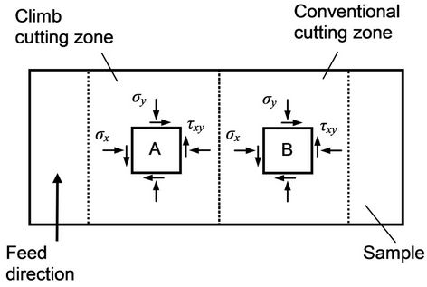
Figure 5. Centroids corresponding to the climb and conventional cutting zones.
bisector of the other directions. Such normal components of the residual strain can be expressed as
 (1)
(1)
where lx and  are the mean values of the horizontal sides of the square defined by indents and, ly and
  are the mean values of the vertical sides, in both cases before and after the distension treatment, respectively. In turn, ld and
  correspond to the positive slope diagonal of the aforesaid square, also before and after the distension, respectively. Then, from the normal components it is possible to obtain the tangential component [19]
 (2)
(2)
Assuming that the generated surface is under a plane stress state and the evaluated material is linearly elastic, homogeneous and isotropic, the residual stress components σx, σy and τxy can be obtained [19]. Finally, the normal and tangential components associated with an arbitrary direction θ (see Figure 3(b)) can be found through
 (3)
(3)
The errors associated with the deformation and stress components were obtained from the absolute error corresponding to the distances between indents. First, the latter was evaluated taking into account both nominal and statistical measurement errors. The obtained range was ±0.2 μm for a nominal distance of 28 mm [15]. Then, by using the probable absolute error equation [20], the ranges obtained for the aforementioned components of the residual deformation and stress were ±0.001% and ±0.9 MPa, respectively.
6. Results and Discussion
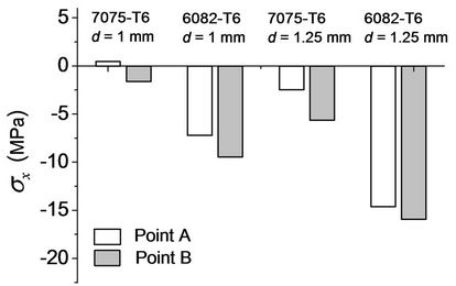
In Figure 6 it can be seen that independently of the evaluated material, the centroid and the process parameter combination, the residual stress components σx and σy are predominantly compressive. This is because, in the case of face milling, an extensive tensile plastic deformation is produced behind the secondary cutting edge. Then the deformation zone is unloaded, which leads to a state of compressive stress. Although Rao and Shin [13] also reported compressive residual stresses in samples of 7075-T6 alloy milled at high speed, the evaluation was limited to only one stress component.
Figure 6(a) shows the normal component σx. It is important to mention that x direction is normal to the feed direction. This figure shows that the more compressive values correspond to the centroid of the conventional cutting zone (point B). Also, it is possible to observe that in the material 6082-T6 the stress levels are more compressive, and that in both materials the stress levels decrease when depth of cut is increased. With regard to Figure 6(b), the behaviour of the component σy is similar to the component σx. However, when both components are compared in detail it can be noted that for alloy 6082-T6, σx > σy and for alloy 7075-T6, σy > σx.
In each milled sample, the small level differences between stresses associated with the climb and conventional cutting may obey to the influence of the relative orientation between Vy and f (see Figure 2) on the generation of local plastic deformation [15]. Regarding the more compressive levels achieved in the alloy 6082-T6,
 (a)
(a)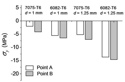 (b)
(b)
Figure 6. Components (a) σx and (b) σy of the residual stress (cutting speed: V = 1000 m/min, feed rate: f = 0.2 mm/rev).
these may respond to thermal reasons because the cutting forces are higher for the material 7075-T6. The differences could be a result of the different fractions of thermal energy from the primary deformation zone to the machined surface, which is always higher for the case of material 6082-T6, mainly due to its higher thermal conductivity [15].
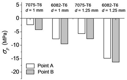
The normal components σp and σq, which correspond to the principal directions are shown in Figure 7. It is noteworthy that on these directions the normal component σx´ reaches its maximum and minimum values [19]. Furthermore, these directions are orthogonal. Figure 7(a) describes the behaviour of σp, which is the more compressive principal component. This behaviour is similar to that of the component σy, showing higher agreement in the case of material 7075-T6. Figure 7(b) describes the behaviour of σq, which is the less compressive principal component. This behaviour is close to that of the normal component σx, also showing higher agreement in the case of material 7075-T6.
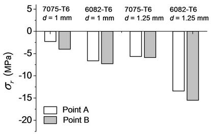
Figure 8 shows the levels that reach the normal components σr and σt, which are associated with the radial and tangential directions, respectively. These directions, which are orthogonal and in turn different for each centroid, are shown in Figure 9. Although Figure 8 shows similar behaviours for σr and σt, the levels of σr are closer
 (a)
(a)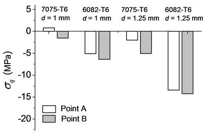 (b)
(b)
Figure 7. Components (a) σp and (b) σq of the residual stress (cutting speed: V = 1000 m/min, feed rate: f = 0.2 mm/rev).
 (a)
(a)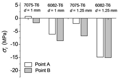 (b)
(b)
Figure 8. Components (a) σr and (b) σt of the residual stress (cutting speed: V = 1000 m/min, feed rate: f = 0.2 mm/rev).
to those of σy, σp (7075-T6) and σq (6082-T6). Additionally, the levels of σt are very similar to those of σx, σp (6082-T6) and σq (7075-T6).
The similarity between the components σr and σy was expected due to the angular difference between their directions is only 26.4˚ (see Figure 9). The same occurs between σt and σx because the angular difference is also 26.4˚. Regarding the principal components σp (7075-T6) and σq (6082-T6), their similarity to σr and σy would indicate that the directions relating to these principal components would be close to the radial and feed directions. Furthermore, the similarity of σp (6082-T6) and σq (7075-T6) with σt and σx would indicate that the directions of these principal components would be close to both the tangential direction and the normal to the feed direction (axis x). Figure 9 shows the directions associated with the more compressive principal component σp. These directions were obtained by evaluating both materials and centroids for the process parameter combination with depth of cut d = 1 mm. In both centroids, the directions corresponding to the material 6082-T6 are situated between the tangential direction and the normal to feed direction. However, for material 7075-T6, such directions are among the tangential and feed directions. Because the latter matches the original rolling direction of material 7075-T6, and the normal to the feed direction equals the original rolling direction of material 6082-T6 (see Figure 1), the obtained results may indicate that these rolling directions would be exerting the greatest influence in relation to the location of the principal directions. As expected, the results also show that the final location of these principal directions would also respond to the strong influence of cutting tangential direction. In consequence, the directions associated with the more compressive principal component σp could be found rotating a certain angle from the rolling direction to the tangential direction, which is satisfied in both materials and centroids. Finally, because in material 7075-T6 the angle between the rolling and tangential directions is greater than in the case of material 6082-T6, it is possible to infer that the main influence would correspond to the rolling direction prior to machining because it is closer than the cutting tangential direction to the mentioned directions associated with the more compressive principal component.
7. Conclusion
The indentation method used in this work allowed us to conduct a comprehensive analysis of residual stress components as well as of principal directions in centroids of different cutting zones and materials. The depth of cut was varied to evaluate the changes of the aforesaid components. Although the values reached by these compo-
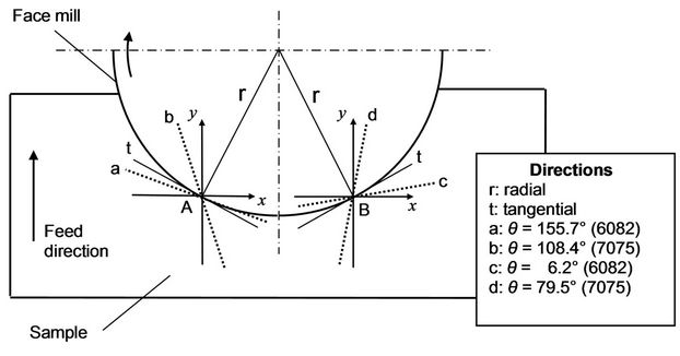
Figure 9. Directions corresponding to the component σp in the centroids A and B (cutting speed: V = 1000 m/min, feed rate: f = 0.2 mm/rev, depth of cut: d = 1 mm).
nents are very small, the technique allows detecting the slight differences generated by changing the depth of cut, the cutting zone or the material. Those components are predominantly compressive due to the extensive tensile plastic deformation generated behind the cutting edge by the face milling. The different stress levels between the evaluated materials could correspond to the different fractions of heat energy diverted to the machined surface, which is always higher for the alloy 6082-T6, mainly because of its higher thermal conductivity. Regarding the more compressive principal stresses, the rolling direction may exert the greatest influence because the principal directions, on which local plastic stretching generated by milling is maximized, are very close to aforementioned rolling direction.
8. Acknowledgements
The authors wish to express their sincere thanks to Eduardo Cravero and Silvio Acosta for their assistance during HSM test phase. This work was supported by the Departamento de Ingeniería Electromecánica and the Departamento de Ingeniería Industrial, Facultad Regional Rafaela, Universidad Tecnológica Nacional.
REFERENCES
- R. M’Saoubi, J. C. Outeiro, H. Chandrasekaran, O. W. Dillon Jr. and I. S. Jawahir, “A Review of Surface Integrity in Machining and Its Impact on Functional Performance and Life of Machined Products,” International Journal of Sustainable Manufacturing, Vol. 1, No. 1-2, 2008, pp. 203-236.
- A. M. Abrão, J. L. Silva Ribeiro and J. Paulo Davim, “Surface Integrity,” In: J. P. Davim, Ed., Machining of Hard Materials, Springer-Verlag, London, 2011, pp. 115- 141. doi:10.1007/978-1-84996-450-0_4
- F. V. Díaz, C. A. Mammana, A. P. M. Guidobono and R. E. Bolmaro, “Analysis of Residual Strain and Stress Distributions in High Speed Milled Specimens Using an Indentation Method,” International Journal of Engineering and Applied Sciences, Vol. 7, No. 1, 2011, pp. 40-46.
- P. J. Withers and H. K. Bhadeshia, “Residual Stress. Part 1—Measurement Techniques,” Materials Science and Technology, Vol. 17, No. 4, 2001, pp. 355-365. doi:10.1179/026708301101509980
- P. J. Hoffman, E. S. Hopewell, B. Janes and K. M. Sharp Jr., “Precision Machining Technology,” Delmar Cengage Learning, New York, 2011.
- E. Brinksmeier, “X-Ray Stress Measurement—A Tool for the Study and Layout of Machining Processes,” Annals of the CIRP, Vol. 33, No. 1, 1985, pp. 485-490. doi:10.1016/S0007-8506(07)61817-4
- J. Hua, R. Shivpuri, X. Cheng, V. Bedekar, Y. Matsumoto, F. Hashimoto and T. R. Watkins, “Effect of Feed rate, Workpiece Hardness and Cutting Edge on Subsurface Residual Stress in the Hard Turning of Bearing Steel Using Chamfer + Hone Cutting Edge Geometry,” Materials Science and Engineering A, Vol. 394, No. 1-2, 2005, pp. 238-248. doi:10.1016/j.msea.2004.11.011
- A. L. Mantle and D. K. Aspinwall, “Surface Integrity of a High Speed Milled Gamma Titanium Aluminide,” Journal of Materials Processing Technology, Vol. 118, No. 1-3, 2001, pp. 143-150. doi:10.1016/S0924-0136(01)00914-1
- B. R. Sridhar, G. Devananda, K. Ramachandra and R. Bhat, “Effect of Machining Parameters and Heat Treatment on the Residual Stress Distribution in Titanium Alloy IMI-834,” Journal of Materials Processing Technology, Vol. 139, 2003, pp. 628-634. doi:10.1016/S0924-0136(03)00612-5
- A. W. Warren, Y. B. Guo and M. Weaver, “The Influence of Machining Induced Residual Stress and Phase Transformation on the Measurement of Subsurface Mechanical Behaviour Using Nanoindentation,” Surface and Coatings Technology, Vol. 200, No. 11, 2005, pp. 3459-3467. doi:10.1016/j.surfcoat.2004.12.028
- J. E. Wyatt and J. T. Berry, “A New Technique for the Determination of Superficial Residual Stresses Associated with Machining and Other Manufacturing Processes,” Journal of Materials Processing Technology, Vol. 171, No. 1, 2006, pp. 132-140. doi:10.1016/j.jmatprotec.2005.06.067
- K. H. Fuh and C. Wu, “A Residual Stress Model for the Milling of Aluminium Alloy (2014-T6),” Journal of Materials Processing Technology, Vol. 51, No. 1-4, 1995, pp. 87-105. doi:10.1016/0924-0136(94)01355-5
- B. Rao and Y. C. Shin, “Analysis on High-Speed FaceMilling of 7075-T6 Aluminum Using Carbide and Diamond Cutters,” International Journal of Machine Tools and Manufacture, Vol. 41, No. 12, 2001, pp. 1763-1781. doi:10.1016/S0890-6955(01)00033-5
- B. Denkena and L. De Leon, “Milling Induced Residual Stresses in Structural Parts out of Forged Aluminium Alloys,” International Journal of Machining and Machinability of Materials, Vol. 4, No. 4, 2008, pp. 335-344. doi:10.1504/IJMMM.2008.023717
- F. V. Díaz, R. E. Bolmaro, A. P. M. Guidobono and E. F. Girini, “Determination of Residual Stresses in High Speed Milled Aluminium Alloys Using a Method of Indent Pairs,” Experimental Mechanics, Vol. 50, No. 2, 2010, pp. 205-215. doi:10.1007/s11340-009-9288-8
- F. V. Díaz and C. A. Mammana, “Study of Residual Stresses in Conventional and High-Speed Milling,” In: L. A. Filipovic, Ed., Milling: Operations, Applications and Industrial Effects, Nova Science Publishers, Inc., New York, 2012, pp. 127-155.
- C. A. Mammana, F. V. Díaz, A. P. M. Guidobono and R. E. Bolmaro, “Study of Residual Stress Tensors in HighSpeed Milled Specimens of Aluminium Alloys Using a Method of Indent Pairs,” Research Journal of Applied Sciences, Engineering and Technology, Vol. 2, No. 8, 2010, pp. 749-756.
- B. Chamberlain, “Maquinability of Aluminum Alloys,” In: Metals Handbook—Properties and Selection: Nonferrous Alloys and Pure Metals, 9th Edition, ASM International Handbook Committee, New York, 1979, Vol. 2, pp 187- 190.
- J. M. Gere, “Mechanics of Materials,” Brooks/Cole, Pacific Grove, 2001.
- P. R. Bevington and D. K. Robinson, “Data Reduction and Error Analysis for the Physical Sciences,” McGrawHill, New York, 2002.
NOTES
*Corresponding author.

