Journal of Power and Energy Engineering
Vol.06 No.02(2018), Article ID:82536,15 pages
10.4236/jpee.2018.62005
Portable Multi-Inputs Renewable Energy System for Small Scale Remote Application
Ibrahim Al-Bahadly
School of Engineering and Advanced Technology, Massey University, Palmerston North, New Zealand

Copyright © 2018 by author and Scientific Research Publishing Inc.
This work is licensed under the Creative Commons Attribution International License (CC BY 4.0).
http://creativecommons.org/licenses/by/4.0/


Received: January 15, 2018; Accepted: February 11, 2018; Published: February 14, 2018
ABSTRACT
This paper presents a potable renewable energy system. The portable renewable energy power unit is designed from a need. The need is for first response teams in remote natural disaster situations to have a reliable source of energy to power a small vaccine refrigerator or water purification system and a basic satellite communication system. It is important that such a need is explored as a practical solution has the potential to save the lives of people in remote areas, who would otherwise suffer from a lack of humanitarian aid. Currently diesel generators are the primary source of electricity generation for disaster responders and in most situations work very well and provide a sufficient amount of electricity to meet the power needs. However, in remote areas road infrastructure is often damaged. In this type of situation getting a constant supply of diesel to the area is an expensive or impractical operation. This is where the portable renewable energy power unit bridges the gap and allows a more practical solution to be implemented. The specific aim of the work is to design a compact, stand-alone, product that can be easily transported by people across uneven terrain. It can generate power from wind, solar and hydro energy sources. In this work a new non-isolated multiport DC-DC converter topology for a hybrid energy system in low power applications is proposed. The new topology assimilates multiple renewable energy sources and power up multiple loads with different output levels. A complete Solid works model and FEA analysis, on required components, is completed. The scope of the work encompasses both the electrical and mechanical design of the system.
Keywords:
Renewable Energy, Wind turbine, Solar Energy, Small Scale Application, Multi-Ports Converter

1. Introduction
Currently diesel generators are the primary source of electricity generation for disaster responders and in most situations work very well and provide a sufficient amount of electricity to meet the power needs. However, in remote areas road infrastructure is often damaged. In this type of situation getting a constant supply of diesel to the area is an expensive or impractical operation. This is where the portable renewable energy power unit bridges the gap and allows a more practical solution to be implemented. This introduction section provides a background overview of the problems and ideas surrounding the research work.
1.1. Background
Energy storage and power generation are some of the largest influences that have driven both the industrial and agricultural sectors in the developed world to what it is today [1] . In addition, a large majority of the world today is powered by finite, unsustainable resources such as fossil fuels [2] . With growing economies and growing populations of people, renewable energy generation, such as solar, wind, and hydro generation is quickly growing as a means of producing electricity for people. Natural Disasters, such as tsunamis, earthquakes and cyclones etc. are uncontrollable events that affect people’s lives with little or no warning. Such events can wipe out homes and destroy power infrastructure, potentially leaving large amounts of people without power, water and sanitary items [3] . Over 50% of New Zealand’s aid for natural disasters goes to the Pacific area. This includes island nations such as the Cook Islands, Fiji, Niue, Samoa, Solomon Islands, Tokelau, Tonga, Vanuatu and others [4] . The pacific region is one of the most prone regions in the world for natural disasters to occur. 3.4 million people in the pacific islands have been directly affected by natural disasters and there have been 1700 reported deaths since 1950 (excluding Papua New Guinea) [5] . Furthermore, New Zealand is within this prone pacific region and experiences natural disasters, which creates demand in cities, towns and remote communities for disaster relief. There are about 100 formal disaster relief organizations worldwide. When a disaster strikes an area, 95% of the work that these organizations do is to address critical needs such as water, food and medical attention. Once these needs are addressed, shelter is the next priority [3] . In order to meet these initial needs for people, in areas that have lost power, having access to a reliable power resource is essential to provide the aid that is needed [6] . Transporting a power generator into a disaster zone has its issues, as often there is restricted access as road infrastructure can be damaged. Moreover, diesel power generators have the continued issue of the transport of diesel into the area; they are also very heavy, make a lot of noise and contribute negatively to preventing greenhouse gas emissions into the atmosphere. Analyzing the trends, this presents a need for a mobile power generation unit, powered by abundant renewable resources such as solar, wind and hydro in order to provide reliable power to aid disaster relief applications. A disadvantage of an individual renewable energy en source in the form of solar radiation or wind is its unreliability. There is not always direct sunshine and likewise, there is not always wind. Also, certain areas are not within close proximity of a flowing river. Furthermore, different environments provide different weather patterns. However, integrating renewable energy sources effectively into one system ensures the reliability of being able to produce power [6] . In addition, energy storage, such as batteries, will enhance the adaptability and reliability of a renewable energy system by being able to cover the fluctuations in the load of the applications being used [7] . As lowering greenhouse gas emissions is a sub-focus for mobile, off-grid, green power systems, it is important that the greenhouse emissions and sustainability of the energy storage systems are considered also as they could be in place for long periods of time [5] [7] .
1.2. Renewable Energy
There are few mobile, hybrid renewable energy systems for disaster relief on the market. Most of the systems currently on the market are singular systems usually consisting of solar generation and the hybrid systems that do exist have very inefficient methods of optimizing wind power capture. Adding energy generation sources has the potential to improve reliability of producing power in any environment. Furthermore, current systems usually need to be towed on a trailer. This makes it difficult to access areas where road infrastructure is damaged and makes it difficult for such systems because of size and weight to be transported into remote areas by air.
From reviewing the literature, it was found that there are two different types of hybrid systems in terms of the choice of energy generation that is currently being developed. The first systems are wind, solar hybrid systems and the second is wind, solar and diesel hybrid systems. The wind, solar, diesel generation hybrids still have the issue of needing access to diesel supply and still emit greenhouse gasses, however, these issues are reduced due to the backup of the solar and wind resources. A third concept that arose within the literature was described as “an ad-hoc self-organized micro-grid based on moveable and renewable energy sources and fully distributed co-ordination between intelligent power routing nodes” [7] . The purpose of this concept is for remote communities and natural disaster victims to be able to rapidly establish a small grid of electricity sharing with little infrastructural development. There is still a lot of research to be done in this area and no working prototype of the proposed system was discovered.
One article was about a product designed by a group of university students called the Mobile Elemental Power Plant (MEPP). This product is a wind, solar hybrid trailer system designed for the use of disaster relief and remote areas [8] .
The system consists of two 240 watt solar panels and a 600 watt wind turbine that is fixed to a telescoping mast system that can raise the turbine 10 metres in the air to gain access of less turbulent, faster flowing air [9] . The whole system is mounted on a trailer for mobility of the system with a vehicle. One issue with having the mobility of the system constrained to a vehicle is that if road infrastructure was destroyed by a disaster it would be difficult to get the system into the area of need. It was further recommended in the article that research be done into the integration of micro-hydro generation to further increase the power reliability and flexibility of the system. Furthermore, a smaller, more mobile version of the MEPP is proposed to increase system agility and reduce cost.
1.3. Energy Storage
One issue related to renewable energy is its variability in its supply of electricity generation. Batteries can be integrated into a system to generate a more constant supply of power to users [4] . Chemical, kinetic or potential energy are all forms in which the electricity produced by the renewable resources can be stored in. The following is a list of storage appliances that can be used to store electricity [9] :
- Batteries,
- Flow batteries,
- Fuel cells,
- Fly wheels,
- Superconducting magnetic energy storage (SMES),
- Super capacitors,
- Compressed air energy storage,
- Pumped hydro.
Compressed air energy storage and pumped hydro are not sufficient for a movable micro-generation due to their size and weight. They are also very costly, therefore more appropriate for large scale energy systems. Super capacitors and SMES have high-power characteristics and their efficiencies are very good compared to other energy storage systems. They can also be drained and recharge numerous times without the capacity of energy storage being lost [10] . SMES and super capacitors are still being developed before they become readily available to purchase on the market at a viable price, therefore they are not reviewed further in this article. According to [4] , flywheels, fuel cells and flow batteries are seen to be more suitable for small renewable energy systems. Flywheel energy storage has high-power and short-cycle characteristics. Energy is lost through friction in the system. Hydrogen/fuel cell technology is environmentally friendly as it uses air and hydrogen to store electricity however, it is not readily available at a viable price to be used for further research. Flow batteries have high-power, low self-discharge but low efficiency characteristics [4] .
1.4. Power Electronics Converter
DC-DC converters are most common and are widely used in renewable energy systems to provide a controlled and regulated supply from an uncontrolled and unregulated renewable energy source [11] . In this work a new non-isolated multiport DC-DC converter topology for a hybrid energy system in low power applications is proposed. The new topology assimilates multiple renewable energy sources and power up multiple loads with different output levels. This new topology has ability to cope with different voltage level requirements and can integrate several energy sources to satisfy the variable load demands. The sources can be utilized independently or simultaneously. Surplus energy can also be stored and made available in case of absence of renewable energy sources. The advantages of the proposed topology over the topologies in the cited literature are:
・ It can accommodate multiple sources at the input.
・ Input sources can be employed independently and concurrently.
・ It can power up multiple loads with different voltage levels.
・ In addition to provide regulated output to the load, this converter can harvest maximum power from the input sources.
・ Surplus energy can be stored in the battery and made available in the absence of renewable energy sources.
2. Proposed System Design
The final solution as shown in Figure 1 is a modular renewable energy system. This means that the wind turbine, Hydro turbine, solar panels and power storage unit are each housed in their own separate unit. This provides many benefits for first response teams going into remote areas:
• A modular setup provides maximum adaptability when packing the system into confined spaces, such as a helicopter or truck, as it can be configured in many different ways to fit in with other supplies and resources. Figure 2 shows image of the solid works final models, consisting of the wind turbine unit, solar module unit, hydro turbine unit and power storage unit. Figure 3 shows flow diagram of the interaction of each module and the supply direction of electricity from each power source, to the selected appliances.

Figure 1. CAD model of the MEPP.

Figure 2. Image of the solid works final models.
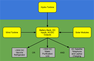
Figure 3. Flow diagram of the interaction of each module.
• The modular design makes human transportation of the system easier as the weight of carrying each wheeled unit can be split between each team member. If the system was integrated as one large unit, the logistics of carrying the unit becomes a lot more difficult as multiple people would have to handle the unit at one time.
• The product is also a lot more adaptable as a modular system in terms of the weather conditions for each circumstance. It is not always necessary that all modules are taken where aid is needed. For example if the weather forecast for an effected remote area predicts a lot of sunshine but little wind and the area is not near a stream or river then it is practical to take only the solar and power storage unit as a power generating resource. In contrast, if the weather predicts rain, with little wind, but the affected area is near a constant flowing stream or river then it may be practical to just take the hydro and power storage unit. As demonstrated this provides a large amount of system adaptability and ensures no unnecessary weight and space is added to the aid supplies.
3. Storage Unit
The new power system is designed to supply electricity to first responders to power their vital equipment. Furthermore the unit provides power redundancy when electricity cannot be produced from the renewable power sources (such as at night). The power generation sources run 12 V DC into the power unit through sockets in the side of the unit. The inputs then run into an Ampair 300 W regulator which regulates the current into the battery. There are two regulators as each regulator can only handle a maximum of two inputs. The battery is a 13.2 V, 100 Ah Lithium Ion Phosphate deep cycle battery, to provide up to 3 hours of redundancy for the system each day. From the battery there are two outputs, one AC and one DC. The AC output runs through a 200 W pure sine wave inverter and the DC output runs directly to a DC socket. In addition a 6 W cooling fan can be turned on, to cool the battery when necessary and all of the external components have rubber caps to seal them off from water or dust. Figure 4 shows the storage unit design with the lid is open and the case has been made transparent for the purpose of being able to display all of the components that make up the complete.
4. Solar Module
The solar array module is designed to capture the suns energy using photovoltaics and convert that energy into electricity, to be sent to the power storage unit. Three 55 W solar panels are connected in parallel to create a 12 V, 165 W solar array. A retractable 12 gauge cable that extends up to 6 metres enables the connection between the solar array and the power storage unit. The unit also has the capability to connect with an additional module to increase the power output in an area that receives a small amount of day light hours. An added solar array connects in parallel with the existing array in order to keep the 12 V output to the power storage unit. The solar arrays angle can be adjusted in order to face perpendicular to the sun at all times of the day, ultimately increasing the arrays power output capacity. The panels fold away into a tough high density polyethylene case which protects the panels from damage when transporting and storing and also protects them from adverse weather when not in use. The soft rubber caster wheels and retractable handle allow ease of human transportation across

Figure 4. Storage unit design.
rough surfaces such as gravel, grass or dirt roads.
Monocrystalline, Polycrystalline and thin film solar panels were considered for the solar array module. The most important factor for choosing the type of solar panel to use was the energy efficiency, as this system requires a high power output from a small, lightweight unit. While slightly more expensive, monocrystalline solar panels have the highest efficiency rates and were therefore chosen to be used on this design [9] . Figure 5 shows image of the front side of the solar array module, consisting of three 55 W solar panels connected in parallel.
5. Wind Turbine Model
The wind module is designed to convert wind energy into electrical energy using a 300 W horizontal axis Am pair wind turbine. The turbine is elevated into the air, to a maximum of 6 meters in order to get into faster, more laminar flowing air. The 12 m long 12 gauge power cord runs from the wind turbine, down the inside of the telescopic tube and out the bottom of the mast holder. The cord has an excess of 6 metres to run to the power storage unit. While the turbine system is a large structure when set up, it can be packed up into a compact casing for transportation and storage. The handle and soft rubber wheels allow the case to be transported easily by a person across semi-rough terrain. Figure 6 in the left

Figure 5. Image of the front side of the solar array module.

Figure 6. The wind turbine out of its case before and after elevation.
is the wind turbine out of its case before elevation, and in the right is the wind turbine at its maximum 6 m elevation, without its guy wires. While Figure 7 shows the wind turbine disassembled and packed into its case.
The wind turbine module went through a range of design changes before arriving at the final design. Initially, like the other module designs, the stand for the turbine mast was integrated into the case. In this instance it was more practical to have the mast and stand separate from the case, due to the cases shape and size. A range of stand variations were investigated in the concept development stage, the final design was chosen due to its simplicity in the number of parts it uses which helps with reducing the weight of the product.
In order to have the turbine reach a setup height of 6 meters the mast material needs to be stiff, strong and lightweight. The two options that were considered for the mast material were aluminum and carbon fiber. As the wind turbine is supported near the top of the mast by guy wires the mast only needs to support a downward force of 1000 N (wind turbine), therefore, it can be assumed the strength of both the aluminum and carbon fiber (using 2 mm wall thickness) tube is of sufficient strength to support the wind turbine. Although slightly more expensive the carbon fiber tubing is 25% lighter than the aluminum and also has a greater stiffness and strength. Therefore carbon fiber tubing was chosen for the product and the weight benefits outweigh the slight increase in price from extruded aluminum.
6. Hydro Turbine Unit
The hydro turbine is designed to be placed into a stream or river and convert the energy from the moving water into electricity from the use of a turbine. As seen in Figure 8 the hydro turbine is housed inside the plastic casing in its transport state, with the soft rubber caster wheels on the underside of the unit allowing the module to be pulled across semi rough terrain by its retractable pull handle. When the module is setup for electricity generation, the heavy duty latches are

Figure 7. Wind turbine disassembled and packed into its case.

Figure 8. Hydro turbine unit in its transportation setup. The case has been made transparent for the purpose of seeing the components within the casing.
undone and the base of the module is flipped 180 degrees. The hydro turbine is then on the outside of the module and the wheels are housed inside the watertight unit as shown in Figure 9. The unit is used as buoyancy for the hydro turbine when it is put into a river or stream, in order to prevent the turbine hitting the riverbed, see Figure 10. A 4 metres carbon fibre telescopic pole used to hold the module out from the riverbank. The pole is held perpendicular to the water flow in tension by a spectra line. Both the pole and the guy line are fixed by 400 mm stainless steel pegs and also have the option to be tied to a fixed object when pegging is not practical. The carbon fibre pole is also housed within the casing when the unit is in its transport state. The 10 metres long 12 gauge power cord runs from the turbine, into the tube and out through the peg. The cord then has an excess of 6 metres to run into the power storage unit.
7. Multi-Inputs Converter Circuit
7.1. Architecture of New Topology
The multiport DC-DC buck converter is shown in Figure 11. The converter interfaces two input sources represented by voltage sources & , a storage element port represented by and an output load port represented by . A single inductor with inductance “L” draws current from both the sources individually and simultaneously. “R” is the load resistance. The converter has five controllable switches and . These switches are responsible for the control of power flow from source to load through their duty cycles and respectively. Switches and are responsible to extract maximum power from the input renewable energy sources. Two Diodes and conduct complementary to the switches and . Diodes are reverse biased during the “ON” state of the switches and and are in the state of conduction during the “OFF” time of switches and . Switches and are
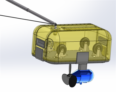
Figure 9. Image of hydro turbine setup for electricity generation.

Figure 10. Image showing the function of the hydro turbine in a flowing river.

Figure 11. Dual input-dual output DC-DC buck converter.
responsible for the control of battery charging and discharging process respectively and the switch regulates the output voltage to a reference value.
7.2. Modes of Operation
In order to analyse the proposed converter, certain assumptions are made, i.e.
・ All the switches are ideal forward conducting reverse blocking.
・ All the losses are neglected.
・ .
・ Output capacitor “C”, is large enough to smooth the output voltage “ ”.
・ It is assumed that the all the connected renewable energy sources are providing DC voltage corresponding to their maximum power point.
The new converter used dual input-single output mode for this application.
This mode of operation is applicable when a single voltage source in not able to satisfy the load demand and needs to be complemented by the second source and if the second voltage source is also not available, the energy stored in the battery can be utilized. This mode is further divided into two sub-modes. Energy transfer action from source to load depends on the control strategy adopted to generate the gate drive signals (Gs) to turn ON the switches and/or . There are numerous different arrangements to turn ON/ OFF the control switches in different switching states ( ), however, six main switching schemes are defined here and shown in Figure 12.
• The switches turned ON and OFF at the same time (Figure 12(a)).
• The switches turned ON at the same time but turn OFF time is different turns OFF first (Figure 12(b)).
• The switches turned ON at the same time but turn OFF time is different turns OFF first (Figure 12(c)).
• The switches are turned ON at different time ( first) and turned OFF at the same time (Figure 12(d)).
• Switch turns ON and after an interval of time switch turns ON. Switch turns OFF first and switch turns OFF later (Figure 12(e)).
• Switch turned ON for a period and then it is turned OFF. Whereas switch is turned on when is turned OFF (Figure 12(f)).
8. Estimated Cost for the New System
The financial information that was considered in this work was the total material/component cost of the final product concept. The cost analysis is a very conservative estimate of costs as a lot of the cost estimates could only be based off the retail value of the components. For example the costs estimated for the solar panels, hydro turbine, and wind turbine are all considered using their retail cost. If a relationship is built with the suppliers and units are purchased in larger quantities, the cost of the components could be reduced significantly. The following are the conservative product part costings, in New Zealand dollars, for the system.
 (a)
(a)
 (b)
(b)
 (c)
(c)
 (d)
(d)
 (e)
(e)
 (f)
(f)
Figure 12. Switching schemes for dual input-single output mode.
・ Power Unit $2269.
・ Solar Unit $1587.
・ Wind Unit $3300.
・ Hydro Unit $2583.
・ Total System Cost $9739.
Each module of the system will be sold separately, allowing customers to adapt their own system to the conditions that most align with the common area that they work within.
9. Conclusions
The portable power generation system is a practical design that fulfils the need for first response teams in remote natural disaster areas, to have a reliable source of energy, to power a small vaccine refrigerator or water purification system and a basic satellite communication system. The system design uses innovative features and materials in order to achieve a product that meets the design specifications of the application.
In this work a new non-isolated multiport DC-DC converter topology for a hybrid energy system in low power applications was presented. The new topology assimilates multiple renewable energy sources and power up multiple loads with different output levels. This new topology has ability to cope with different voltage level requirements and can integrate several energy sources to satisfy the variable load demands. The sources can be utilized independently or simultaneously. Surplus energy can also be stored and made available in case of absence of renewable energy sources.
The system fills a niche in the market for a self-sustaining power unit that can be successfully transported by foot or by air into affected remote disaster locations. Because the system is the only product of its kind, there is a reasonable opportunity for the adoption, by non-profit aid organizations who are involved in disaster relief, as natural disasters are always going to exist and are increasing with global warming. With the increase in renewable energy technologies, the long term success of such a product is promising.
Acknowledgements
The author wishes to thank the students and the workshop-technical staff at Massey University-School of Engineering and Advanced Technology for their help and support in this work.
Cite this paper
Al-Bahadly, I. (2018) Portable Multi-Inputs Renewable Energy System for Small Scale Remote Application. Journal of Power and Energy Engineering, 6, 59-73. https://doi.org/10.4236/jpee.2018.62005
References
- 1. Ambia, M.N., Islam, Md.K., Shoeb, Md.A., Maruf, Md.N.I., and Mohsin, A.S.M. (2010) An Analysis & Design on Micro Generation of a Domestic Solar-Wind Hybrid Energy System for Rural & Remote Areas—Perspective Bangladesh. 2010 2nd International Conference on Mechanical and Electronics Engineering (ICMEE), Kyoto, 1-3 August 2010, 107-110.
- 2. Mcculley, J.K. (2013) Mobile Elemental Power Plant (MEPP). 2013 1st IEEE Conference on Technologies for Sustainability (SusTech), Portland, 1-2 August 2013, 109-113. https://doi.org/10.1109/SusTech.2013.6617306
- 3. Young, W. and Reinarts, R. (2007). Solar 2007: Renewable Energy Disaster Relief Fund Gives a Helping Hand. Florida Solar Energy Center, Cleveland, OH, 1-6. http://www.fsec.ucf.edu/en/publications/pdf/FSEC-PF-431-08.pdf
- 4. McGregor, A. (2014) UNANZ News. University of Victoria, Wellington.
- 5. Department of Conservation (2006) Review of Camping Opportunities in New Zealand. Report to the Minister of Conservation. Department of Conservation, Wellington.
- 6. Kaabeche, A. and Ibtiouen, R. (2014) Techno-Economic Optimization of Hybrid Photovoltaic/Wind/Diesel/Battery Generation in a Stand-Alone Power System. Solar Energy, 103, 171-182. https://doi.org/10.1016/j.solener.2014.02.017
- 7. McManus, M.C. (2012) Environmental Consequences of the Use of Batteries in Low Carbon Systems: The Impact of Battery Production. Applied Energy, 93, 288-295. https://doi.org/10.1016/j.apenergy.2011.12.062
- 8. Victoria University of Wellington (1999) New Zealand Defence Spending. University of Victoria, Wellington.
- 9. Maehlum, M.A. (2017) Which Solar Panel Type Is Best? Mono-, Polycrystalline or Thin Film? http://energyinformative.org/best-solar-panel-monocrystalline-polycrystalline-thin-film/
- 10. Dunstan, K. and Thomson, N. (2006) Demographic Aspects of New Zealand’s Ageing Population. Stats New Zealand, Wellington, 1-44.
- 11. Rehman, Z., Al-Bahadly, I. and Mukhopadhyay, S. (2015) Multiinput DC-DC Converters in Renewable Energy Applications—An Overview. Renewable & Sustainable Energy Reviews, 41, 521-539. https://doi.org/10.1016/j.rser.2014.08.033