World Journal of Engineering and Technology
Vol.05 No.04(2017), Article ID:79735,12 pages
10.4236/wjet.2017.54051
Collision Analysis of the Unconventional Double Hull of a Ship
Adrian Presura, Ionel Chirica
University Dunarea de Jos of Galati, Galati, Romania

Copyright © 2017 by authors and Scientific Research Publishing Inc.
This work is licensed under the Creative Commons Attribution International License (CC BY 4.0).
http://creativecommons.org/licenses/by/4.0/


Received: September 21, 2017; Accepted: October 16, 2017; Published: October 20, 2017
ABSTRACT
Following to the great accidents the interest in preventing environmental pollution and the safety of people and means of maritime transport have increased. The idea of developing new, unconventional structures, imposed by the new requirements of Shipbuilding Rules related to safety and pollution is analyzed in the paper. The behavior of the unconventional double hull of a ship structure concept, named ARC, loaded to transversal impact is treated. In the paper the finite-element analysis is used because is important to provide the structural designer that no stress concentrations exist in a certain design. The results obtained for energy absorption and general ship hull behavior encouraged the authors to introduce in shipbuilding the unconventional double hull of the ship structure concept.
Keywords:
Collision, Ship Double Hull, Unconventional Ship Structure, FEM Analysis

1. Introduction
Double hull of a ship is a ship hull with double layers of watertight hull surface. The inner and outer layers of the hull are on the bottom as well as the sides of the ship. The double layer construction is designated to reducing the risks of marine pollution during collision, grounding, and any other form of ship’s hull damage. After the great disasters performed by the Exxon Valdez oil spill disaster and sinking of Erika off the coast of France in December 1999, The International Maritime Organisation (IMO) introduced the regulation 13 F of Annex 1 of MARPOL [1] , which effectively require double hulls for new built oil tankers of 5000 dead weight tonnage and above.
Structures of ballast spaces in double hull tankers are more susceptible to hull fractures and minor failures as a result of stress concentration, fatigue, or construction defects.
In the paper, extensive finite-element stress analyses in the case of transversal impact have been done on unconventional double hull of a ship structure concept. The analyses are important to provide the structural designer that no stress concentrations exist in a certain design.
In [2] a study on unidirectional longitudinal framing systems, to obtain improved productibility, maintainability, and resistance to casualties is performed. Study results are applied to the design of commercial product and crude oil tankers and naval combatants. Interim results of analytical, experimental, and design studies are presented, with corresponding tentative conclusions. The investigations related to structural integrity have focused on resistance to grounding. The authors have found that the advance double hull absorbs nominally more energy than a conventionally framed hull.
In [3] a study to investigate the environmental consequences of the involvement of oil tankers in collision is presented, by using probabilistic approaches. Scenarios of ship-ship collision are selected to create a representative sample of the most possible ones. The environmental consequences are then estimated by calculation of the amount of oil spilled in each scenario. In addition, the potential damage to the environment is presented in terms of monetary units that can be understandable to all stakeholders.
Unconventional double hull structures have been developed as a more efficient response to the requirements of collision strength, in case of a ship collision or grounding.
PNTL (Pacific Nuclear Transport Limited) [4] is a maritime transport company of nuclear fuel type products (MOX fuel) and the resulting waste. Considering the high risk level of this type of cargo a double side structure has been adopted which extends on 20% from the ship beam and which has an interior additional strengthened structure with horizontal 20 mm thick plates to improve the collision behavior. The additional structure weighs approximate 400 t of steel supplementary to the ship structure, which represents approximate 40% from the mass of the steel ship conventional structure.
In the European research project MoVe IT! [5] a “Y” type double hull structure was analyzed. The concept is based on use of “Y” type structure elements between exterior and interior shells. In contrast with classical double hull the “Y” concept replaces the orthogonal stringers and the transverse web frames with the structure. The “Y” shape cell as the flanges directioned to the outer shell. The geometry of the “Y” profile is described by the hight “h” of the leg, value “e” of the web, inclining angle “α” of the flanges, thickness “t”, spacing “L” and the total width “H” of the double hull structure. Similarly, by analogy with “Y” structures, the “λ” type double hull structure was analyzed.
Additionally, in [6] double hull with steel-polystyrene-steel sandwich (MoVe IT!, 2014). The concept consists of a double hull with XPS foam blocks at interior. The studies have concerned grounding and ship-ship collision and encouraging conclusions have been performed.
2. Key Study and Hypotheses
2.1. Description of Key Study
The analysed ship is a tanker for inland waterways having the following characteristics:
Length overall: 99.90 m
Breadth: 9.45 m
Depth: 4.75 m
Scantling draught: 3.20 m
Block coeff. CB: 0.9
Frame space: 625 mm
Web frane space: 1875 mm
Only a piece of ship hull from the midship, has been analysed, extending on one cargo hold length and including a corrugated transverse bulkhead.
Conventional analyzed structure is provided with double side of 0,8m width and double bottom of 0.7 m height in center line and 0.9 m at double side, ensuring practically for cargo area an ratio volume of cargo tanks/total volume of 70%.
Deck, bottom and double bottom, side and double side structures are in longitudinal framing system, otherwise are provided simple frames on the side at every 625 mm and web frames on all structures at every 1875 mm. In Figure 1 is illustrated an overview of the structure.

Figure 1. 3D model of structure.
In order to estimate the capacity of impact energy absorption, in collision case, a finite element analysis was performed in plastic deformation with a dynamic loading.
The unconventional solution of double hull is based on the idea of strengthen the inner side with transversal structural elements of arc shape. The name of this solution is “ARC”. In the same time, light elements have been used to compensate the weight of the supplementary elements added to the conventional double hull structure. In Figure 2 are illustrated the “ARC” structure additional elements.
The “ARC” structure can be a solution to modify existing structures, but can also be used to re-design new structures.
2.2. Rules Requirements and Analysis Hypothesis
Finite element calculations of ship structures have to meet requirements imposed by the rules of the ship classification societies [7] .
All structural elements have to be modeled with net thickness (without corrosion addition etc.), in consequence the strength and rigidity will be reproduced according to this thickness.
The model extension on longitudinal way has to take into account that the results from the analyzed area are not influenced by the boundary conditions. In the case of the center line symmetry the structure model can be done only on half of the ship.
Mechanical characteristics of the material used for the structure are according to steel S235, from Det Norske Veritas RP-C208 [8] :
− Young’s modulus, E = 2.1 × 10⁵ MPa
− Yield stress RY = 236.2 MPa
− tangent modulus 1105 MPa
− Poisson’s ratio 0.3

Figure 2. Web frame (left) and simple frame (right) of “ARC” structure.
Additionally, the ultimate criteria according to strain εk = 0.171, was used. This criteria is obtained from [9] , such as:
(1)
where
εg = 0.08
εe = 0.65
t = 7 mm is the average thickness of the elements
le = 50 mm is the average length of the elements.
According TO BV Rules, 2016 [10] and ADN, 2017 [7] the following boundary conditions have been used:
− all three displacements fixed at fore end of the structure model,
− symmetry conditions in transversal plane,
− symmetry conditions in center line.
The friction between the bow and the side was considered with constant friction coefficient μ = 0.3. The friction coefficient has been estimated according to European Agreement concerning the International Carriage of Dangerous goods by Inland Waterways [7] :
(2)
where:
FD = 0.1
FS = 0.3
DC = 0.01
is relative friction speed.
The loading of the model was made by considering an initial kinetic energy to the bow model defined by through:
− initial speed 4 m/s on transverse direction, direction Oy,
− bow model weight is of 750 t.
The ship bow indenter is the bow of a classical inland ship, suggested by ADN, 2017 [7] , which is considered as a rigid, having the relative positions illustrated in Figure 3.

Figure 3. The relative position ship hull structure vs. ship bow indenter.
2.3. Appreciation Criteria
The following criteria have been taken into account for unconventional double hull structures analysis:
− the behavior until end of the impact (total internal energy, the length of total penetration),
− the behavior until the collapse of the tank bulkhead (total internal energy, the length of total penetration),
− structure weight (idea to obtain a light structure),
− the efficiency of the structure (rate total intenal energy/weight).
3. Unconventional Double Hull Structure Analysis
For the plastic-dynamic analysis by using FEM, the module ANSYS-Explicit Dynamics [11] has been used.
According to ADN requirements, [7] , the criterion for assessing the strength of a ship's structure at impact with another ship is given by the energy absorbed by the structure until the cargo tanks break.
In the following chapters the numerical simulation results are presented.
3.1. General Deformation
In Figure 4 the permanent deformation of the structure is illustrated. The penetration of the bow of the ship-indenter is observed.
3.2. The Failure of the Double Side
Figure 5 shows the state at time t = 0.69 s in which the first elements of the tank wall were yielded and the right situation at time t = 0.73 s at the end of the impact.
By analyzing the equivalent stress map at various intermediate moments, it is noted that the area of stress concentrators generated by the contact between the outer shell and the inner side was taken over by the added stiffener elements. At the same time, it is noticed that vertical failure of bulkhead tanks have not been


Figure 4. Final deformation of the structure.


Figure 5. The release of the double side at t = 0.69 s.
initiated, and the inner side failure has occurred in a much narrower area and only at the fore area of the deck (Figure 6).
3.3. Internal Energy of the Structural Elements
In order to assess the level of participation of the stiffeners in the total deformation of the structure during the impact, the internal energy map was analyzed at the end of the calculation at time t = 0.73 s.
From Figure 7, where the stiffeners deformations are presented, it is noted that the added structural elements generally have a high level of deformation energy.
From the figures can be more accurate estimated the participation of each structural element to the deformation process during collision.


Figure 6. The failure of the tank bulkhead.


Figure 7. Internal energy in stiffeners after failure.
3.4. Local Deformations
Analyzing the map of the deformations of the unconventional structure we found the following: a deeper deformation of the deck due to arched elements, as it is seen in Figure 8 and reduction of bottom and double bottom bending (Figure 9) in comparison with conventional structure.
In Figure 10 the variations of kinetic energy and internal energy versus time of the structure are illustrated. As it is seen, the maximum internal energy value is reached at time t = 0.73 s.
Figure 11 shows the movement of the bow-indenter model in the transversal direction versus time. A strong deceleration is observed in the first part of the collision, up to t = 0.42 s, followed by a reduced braking in the second part.

Figure 8. Deck deformation.

Figure 9. Bottom and double bottom bending.
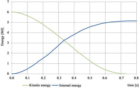
Figure 10. Kinetic energy and internal energy versus time.

Figure 11. Time variation of the bow-indenter displacement.
4. Conclusions
Following to the FEM analysis, the results obtained to the end of the impact (the moment of double side failure) are: total internal energy is 5.633 MJ, maximum displacement is equal to −1.820 m and ratio internal energy/structure mass equal to 0.446 MJ/t.
By comparison with the conventional structure it is observed that the unconventional structure shows a faster decrease of the kinetic energy throughout the phenomenon compared to the conventional structure. The unconventional structure consumes total kinetic energy at a final time t = 0.8 s, that is 20% earlier than the conventional structure.
On the other hand, the weight of the analyzed unconventional structure model is increasing by 6.2% regarding to the conventional structure, which means an increase of 18 t of the entire structure of the vessel, which translates into a 20 mm increase in the draft of the ship.
To build this structure it is possible to use accessible materials (customary naval steel) and to use usual assembly technology, that means welding,
The “ARC” structure complies with the 2017 requirement for the inspection of compartments adjacent to the cargo tanks, the added structural elements do not impede access and movement through the double and double bottom spaces.
Using of unconventional structure analyzed in the paper involves modernization in the following directions:
− the addition of the “arch” cross-sectional elements inside of the double-sided panel, of a thickness of 6.5 mm
− Relief of deck transverses structure, floors, shoulder and side girders.
Benefits of using ARC structure are obtained by increased internal energy (46.6% compared to the conventional structure), simple technology (basically the “arc” elements are made of common steel and the usual shipbuilding technology).
Of course for certain cases the using of ARC structure involves disadvantages: in the case of viscous cargo such as oil, asphalt etc., the “arc” elements used to the cargo tanks can create functional problems (complication of the heating system, accumulation of substances transported around structural elements, tanks washing process can be difficult). Also, ARC structure cannot be applied to bulk or container type vessels.
Acknowledgements
The authors would like to thank SHIP DESIGN GROUP Ltd. for their help in providing data and support to this research study. Some parts of this work are included as a chapter in the doctoral thesis “Stress States that Occur in Ship Unconventional Double Hull Structures”, made by Adrian Presura.
Cite this paper
Presura, A. and Chirica, I. (2017) Collision Analysis of the Unconventional Double Hull of a Ship. World Journal of Engineering and Technology, 5, 601-612. https://doi.org/10.4236/wjet.2017.54051
References
- 1. MARPOL 2006 - International Convention for the Prevention of Pollution from Ships - International Maritime Organization 2006.
- 2. Melton, W., Beach, J., Taylor, D., Gagorik, J., Roseman, D. and Sikora, J. (1994) Advanced Double Hull Research and Development for Naval and Commercial Ship Application. SNAME Transactions, 102, 295-323.
- 3. Kim, Y.S., et al. (2015) Environmental Consequences Associated with Collisions Involving Double Hull Oil Tanker. Ships and Offshore Structures, 10, 479-487.
- 4. PNTL - Double Hull. http://www.pntl.co.uk
- 5. MOVEIT! - Modernisation of Vessels for Inland Waterway Freight Traffic. http://www.moveit-fp7.eu/
- 6. MOVEIT! - Modernisation of Vessels for Inland Waterway Freight Traffic - Work Package WP5 Structures & Weight, Task 5.3 Crashworthiness (TNO, SMILE FEM, University Galati, Ship Design Group, SWEREA Sicomp), 2014.
- 7. ADN, 2017 - European Agreement Concerning the International Carriage of Dangerous goods by Inland Waterways - United Nations 2016.
- 8. DNV Rules, 2015 - Rules for Classification of Ships - Edition January 2015.
- 9. Peschmann, J. (2000) Berechnung der Energieabsorption der Stahlstruktur von Schiffen. [Calculation of the Energy Absorption of the Steel Structure of Ships]. TU Hamburg-Harburg.
- 10. BV Rules, 2016 (NR467) - Bureau Veritas - Rules for the Classifiction of Steel Ships - Edition July 2016.
- 11. ANSYS Release 17 January 2016 - ANSYS Explicit Dynamics Analysis Guide.