Open Journal of Safety Science and Technology
Vol.05 No.02(2015), Article ID:57161,7 pages
10.4236/ojsst.2015.52007
Microcontroller Based Home Security System with GSM Technology
Raqibull Hasan, Mohammad Monirujjaman Khan, Asaduzzaman Ashek, Israt Jahan Rumpa
Department of Electrical and Electronic Engineering, Primeasia University, Dhaka, Bangladesh
Email: monirkhan.qmul@gmail.com
Copyright © 2015 by authors and Scientific Research Publishing Inc.
This work is licensed under the Creative Commons Attribution International License (CC BY).
http://creativecommons.org/licenses/by/4.0/


Received 5 February 2015; accepted 11 June 2015; published 15 June 2015
ABSTRACT
In this paper, design and implement of a microcontroller based home security system with GSM technology have been presented and analyzed. Two microcontrollers with other peripheral devices which include Light Emitting Diode (LED), Liquid Crystal Display (LCD), Buzzer and Global System for Mobile Communication (GSM) Module are responsible for reliable operation of the proposed security system. In addition, a mobile phone is interfaced with microcontroller through a Bluetooth device in order to control the system. Moreover, a manual keypad is another way to lock or unlock the system. A Compiler Code Vision AVR is used to design a program that controls the system along with maintaining all security functions. The designed program is applied in Proteus Software for simulation. At last, the results of practical circuit show the proper functions and also verify the reliable security within reasonable cost.
Keywords:
Home, Securıty, System, Control, Microcontroller, Bluetooth, GSM

1. Introduction
Home automation is a process for improving the quality of resident’s life by facilitating a flexible, comfortable and secure environment [1] . Home security system is the most prominent feature for home automation. Traditional techniques of alarm based security have gained much popularity in past decades. Nowadays, embedded system is designed to provide security due to tremendous improvement in microcontroller unit and widespread applications of GSM technology. In literatures, researchers suggested a number of security systems based on new technologies like GSM, GPRS (General Packet Radio Service), Internet, USN (Ubiquitous Sensors Network) and implemented through FPGA (Field Programmable Gate Arrays), ASICs (Application Specific Integrated Circuit), DSP (Digital Signal Processing), and MCU (Microcontroller Unit) [2] . In [3] [4] , home automation system has been explained using FPGA, GSM, Internet and Speech Recognition. In this system, the home gateway is internet which requires personal computer (PC). However, it is difficult to manage PC and keep it ON all the time which also consumes more power. The system presented in [5] is an internet-based intelligent system for home power management aiming to reduce energy consumption. This system also uses internet cloud as a home gateway having the same limitations as described earlier. A java equipped mobile based home automation system is described in [6] . Although the research proposes an embedded home server but it still requires internet connectivity for GPRS. In [7] , authors proposed a zigbee based home network configuration which controlled all home appliances through zigbee-infrared combination and zigbee power adapter. Lee et al. in [8] proposed a wireless network protocol providing a bidirectional communication channel between a gateway and the control device, highlighting the significance of wireless sensors network in controlling home appliances. In [9] , PIC18F452 microcontroller based home security system has been designed without GSM technology. In this paper, ATMEGA16 microcontroller based home security system with GSM technology has been described. In addition, Bluetooth application has been used to control the system. Consequently, the proposed system provides reliable security within reasonable cost and also removes the circuit complexity.
In this work, firstly proposed system will be described in section 2 which includes software design process and implementation of practical circuit. Moreover, Section 3 will present the results along with discussing the functional sequence of practical circuit. Finally, section 4 will summarize the whole research.
2. Proposed System
General block diagram of the proposed microcontroller based home security system has been shown in Figure 1. It consists of three sections. Those are input, controller and output sections. At first the controller section remains at waiting state for receiving a signal from input section which includes Bluetooth, 4 × 4 Keypad, Pressure sensors and a mobile phone. In input section, a mobile phone through a Bluetooth device has been used for interfacing with microcontroller to lock or unlock the door of the system. Consequently, a manual keypad performs the similar function without communication with Bluetooth device. On the other hand, pressure sensors have been placed both at door and window to protect the system.
If anyone tries to unlock the system without authority, then those sensors will activate and controller will receive a suitable pulse. According to the pulse of input devices, the controller section takes decision and activates the output section which includes LCD display, GSM Module, Servo Motor, LED and Buzzer. However, the ac-
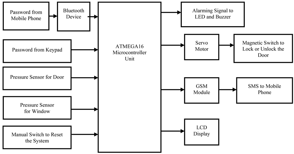
Figure 1. General block diagram of proposed home security system.
tivation of output device depends on the activity of input section that indicates user unlock the system either authoritative or without authoritative way. For authoritative way, controller sends a pulse signal to the servo motor that is also connected with a magnetic switch placed with a door. After 90 degree rotation of servo motor activates the magnetic switch which is used to lock or unlock the system. At the same time, a message is displayed at LCD. Conversely, at without authoritative way controller sends signal to the LED, Buzzer and GSM Module simultaneously. LED has been placed surrounding the home which indicates something wrong events that have occurred within the system. Consequently a Buzzer produces sound signal and GSM module throws a message towards the owner’s mobile phone. Those activities are easily aware both the owner and security guard. As a result they will detect the mal operation within the system. At last a reset switch is used to regain the whole system at normal condition.
The proposed system includes two parts such as: software and hardware. At software part, a program has been designed in Code Vision AVR Software according to the functional sequence of block diagram. In accordance to software instruction a suitable circuit diagram has been designated for hardware implementation.
2.1. Software Design
The program flow chart of the proposed home security system has been shown in Figure 2 which explains the
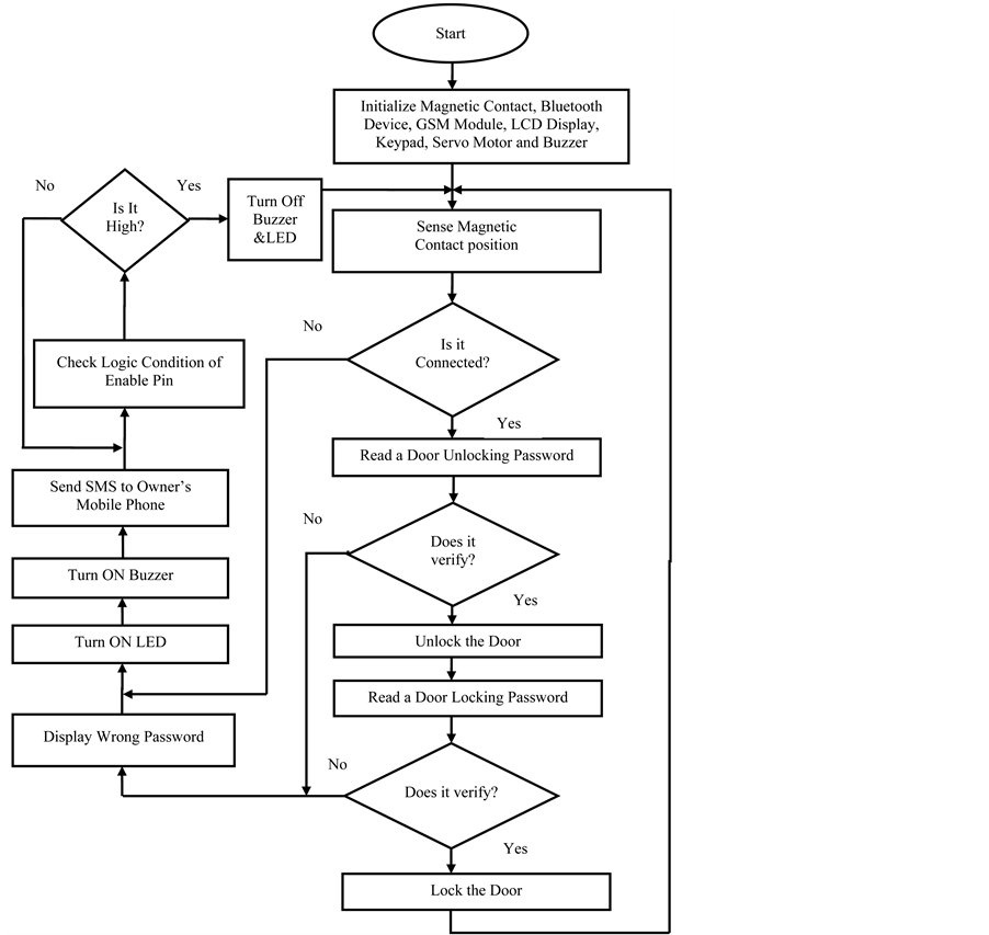
Figure 2. Program flow chart of the proposed home security system.
whole software design procedures. Software Code Vision AVR is used as a compiler for designing the program in C-Language. The proper instructions perform the desired function sequentially according to the flow chart. At first, the program initializes all peripheral devices (Magnetic Contact, Bluetooth Device, GSM Module, LCD Display, Keypad, Servo Motor and Buzzer). This is the precondition for interfacing between microcontroller and peripheral devices. Then the program examines the magnetic contact’s position either it is connected or separated. If it is connected with door or window, then the program will give the authority to enter a password that will lock the door. Otherwise program instructions have been mentioned for mal-operation resulting it sends signal to the LED, Buzzer and GSM Module for their individual function sequentially. On the contrary, after receiving a password program verifies the password with the door unlocking password. If the result is affirmative, the program will give the authority to unlock the door. Otherwise mal-operation indicates in LCD by displaying an error message and also the previous functions remain unchanged. However, program remains at waiting state for receiving a door locking password after getting the permission to access the system. Similarly program verifies the password resulting it locks the door. Otherwise it sustains the mal-operation until reset pin is high.
However, the instructions in program flow chart have been represented in Figure 2 which maintains the following procedure for the proper operation of proposed home security system.
1) Start;
2) Initialize Magnetic Contact, Bluetooth, GSM module, LCD display, Keypad, Servo Motor and Buzzer;
3) Sense the magnetic switch position;
4) If the magnetic switch is connected, the system will remain at waiting state for receiving a password. Otherwise, the system will turn on the alarming signal and send SMS to the owner’s mobile;
5) Receive a password from keypad due to unlock the system;
6) Verify the password with the unlocking password which is mentioned in program. If the input password is exactly equal to the system password, a pulse signal will send to the servo motor which will pressurize the door resulting the system will be unlocked. Otherwise, LCD display will show wrong password and the system will follow the similar procedure which is mentioned in step 4 for the false condition, and the system will jump to step 7.
7) Receive a password from keypad due to lock the system. After opening the door, the system will remain at waiting state for receiving a number which is designated for locking the door.
8) Verify the password with the locking password which is mentioned in program. If the input password is exactly equal to the system password for closing the door, the system will be locked and return to step 3. Otherwise, the system will operate at false mode and follow the similar procedure mentioning in step 5.
9) Check the logic condition of enable pin. If it remains at low state, the system will sustain the mal-operation and remain at waiting state until it will obtain high logic condition. On the contrary, the system will start again from step 2 for the high logic condition of enable pin.
2.2. Hardware Design
The implementation of practical circuit has been designated using Proteus Software as shown in Figure 3. Moreover, the circuit is also simulated using this software before practical implementation. The result of simulation ensures that the circuit works at proper way. The practical implementation of simulated circuit has been presented in Figure 4. In this circuit diagram two microcontrollers are the main components which are used for controlling other devices (Magnetic Contact, Bluetooth Device, GSM Module, LCD Display, Keypad, Servo Motor and Buzzer). Among the controlling devices, Magnetic Contact is used as a sensor for determining the present status of the system. This device will operate when the position of magnetic contacts are separated due to pressure from external environment. Bluetooth technology is a networking protocol that allows two or more devices to connect with each other through a Personal Area Network (PAN). In this part, Bluetooth device is used as a medium for the communication between microcontroller and mobile phone. A Servo Motor consists of three major parts: a motor, control board, and potentiometer (variable resistor) connected to the output shaft. The motor utilizes a set of gears to rotate the potentiometer and the output shaft at the same time. The potentiometer controls the angle of the servo motor and allows the control circuitry to monitor the current angle of the servo motor. If the control circuit detects that the angle is not correct, it will turn the servo motor to the correct direction until the angle is correct. In this system, the servo motor is used to control an angular motion between 0 and 90 degrees. Moreover, GSM is a standard developed by the European Telecommunications Standards Institute

Figure 3. Schematic diagram of the proposed home security system.
(ETSI) to describe protocols for second generation (2G) digital cellular networks used by mobile phones. So, GSM Module makes a strong wireless communication network between owner and security system.
However, the system receives signal from input devices (Magnetic Contact, Bluetooth Device, Keypad) and sends signal to the output devices (LCD Display, Servo Motor, LED and Buzzer) in order to maintain security.
3. Results
In this section, firstly Figure 5 & Figure 6 describe the overall procedures in order to lock or unlock the system using Keypad or Mobile Phone. Then the result from mal-operation is also presented in Figure 7.
Figure 5(a) shows a practical implementation of home security system which is receiving a password from physical environment to unlock the door. This function is accomplished by interfacing with keypad and microcontroller. Moreover, the password is displayed at LCD and the system remains at waiting state until password is conformed from user end.
Figure 5(b) shows that the system has been unlocked by the rotation of servo motor and separation of magnetic contacts after verifying the password. At the same time, a conformation message “DOOR OPEN” is displayed at LCD. This indicates someone is accessing the system in proper way. However, the system again returns at initial mode for receiving another password in order to lock the system. This password is also displayed at LCD until the password is verified from controller section.
In Figure 5(c), the system has become locked after the verification of door locking password. To perform this

Figure 4. Hardware setup for home security system.
 (a)
(a)
 (b) (c)
Figure 5. Interfacing between Keypad and Microcontroller resulting the system (a) receives password, (b) open and (c) close the door.
function, microcontroller sends a signal to the servo motor and magnetic contacts so that servo motor rotates at reverse order resulting it pressurizes the door along with connecting the magnetic contacts. Moreover, the system also ensures the functions by displaying a conformation message “DOOR CLOSED” at LCD. This message also indicates that the system has been locked without any mal-operation.
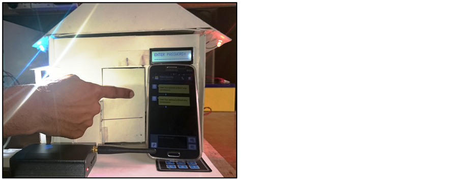
In Figure 6, the android application has been implemented through a Bluetooth device in order to control the system. In this work, an android mobile phone is used for accessing the system without help of Keypad. At first, mobile phone sends a signal to the Bluetooth device through a wireless medium. Then the transmitting signal is received by microcontroller from Bluetooth device which is directly connected with microcontroller. Using mobile keypad if anyone enters a wrong password, the system will activate the security mode. On the contrary, after getting an appropriate password system ensured the proper function by displaying a conformation message at LCD. Password system from mobile phone has been accomplished by designing mobile apps for android application.
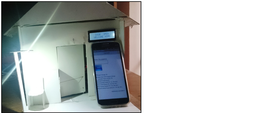
Figure 6. Implementation of Android application.
 (b) (c)
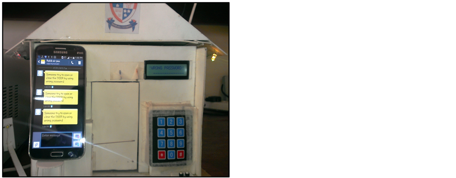
Figure 7. Mal operation introduced by (a) wrong password and (b) breaking door.
Figure 7(a) shows the practical implementation of mal-operation which has been occurred by pressing wrong password. As a result the system activates all the security system. This includes an alarming message to owner mobile phone, turn on the Buzzer and LED. The system sustains the hazardous condition until the whole system is become reset.
In Figure 7(b), another mal-operation is introduced by breaking the door without authentication. In this case, microcontroller activates GSM Module, LED and Buzzer. Consequently, the system follows the similar procedure described in previous wrong condition in order to maintain security. Moreover, the system performs the similar security functions in order to protect windows.
4. Conclusion
This paper presents design and implementation of a smart home security system based on microcontroller along with GSM for user friendly application. The system is intelligent enough to monitor the secure environment. In addition, the user is informed about the security breach through GSM network that provides a special opportunity whenever the user stays at far away from home. However, Android application is the most stunning feature in order to control the system through a Bluetooth device. Moreover, the system provides the reliable operation within reasonable cost and removes the system complexity. In this work, traditional burglar alarm mode, LED lights and LCD are the promising features used to ensure reliability. The whole system is implemented on a practical home security system which requires considerable effort to install it. Consequently, the system is also applicable for commercial purposes due to versatile ways of security and controllability.
References
- Rana, G.M.S.M., Khan, A.A.M., Hoque, M.N. and Mitul, A.F. (2013) Design and Implementation of a GSM Based Remote Home Security and Appliance Control System. Proceedings of the 2nd International Conference on Advances in Electrical Engineering, Dhaka, 19-21 December 2013, 291-295.
- Ahmad, A.W., Jan, N., Iqbal, S. and Lee, C. (2011) Implementation of ZigBee―GSM Based Home Security Monitoring and Remote Control System. IEEE 54th International Midwest Symposium on Circuits and Systems, Seoul, 7-10 August 2011, 1-4. http://dx.doi.org/10.1109/mwscas.2011.6026611
- El-Medany, W.M. and El-Sabry, M.R. (2008) GSM-Based Remote Sensing and Control System using FPGA. Proceedings of International Conference on Computer and Communication Engineering, Kuala Lumpur, 13-15 May 2008, 1093-1097.
- Yuksekkaya, B., Kayalar, A.A., Tosun, M.B., Ozcan, M.K. and Alkar, A.Z. (2006) A GSM, Internet and Speech Controlled Wireless Interactive Home Automation System. IEEE Transactions on Consumer Electronics, 52, 837-843. http://dx.doi.org/10.1109/TCE.2006.1706478
- Golzar, M.G. and Tajozzakerin, H.R. (2010) A New Intelligent Remote Control System for Home Automation and Reduce Energy Consumption. 4th Asia International Conference on Mathematical/Analytical Modelling and Computer Simulation, Kota Kinabalu, 26-28 May 2010, 174-180.
- Van Der Werff, M., Gui, X. and Xu, W.L. (2005) A Mobile-Based Home Automation System. Proceedings of the 2nd International Conference on Mobile Technology, Applications and Systems, Guangzhou, 15-17 November 2005, 1-5.
- Hwang, I.-K., Lee, D.-S. and Baek, J.-W. (2009) Home Network Configuring Scheme for All Electric Appliances using ZigBee-Based Integrated Remote Controller. IEEE Transactions on Consumer Electronics, 55, 1300-1307. http://dx.doi.org/10.1109/TCE.2009.5277992
- Lee, H.-B., Park, J.-L., Park, S.-W., Chung, T.-Y. and Moon, J.-H. (2010) Interactive Remote Control of Legacy Home Appliances through a Virtually Wired Sensor Network. IEEE Transactions on Consumer Electronics, 56, 2241-2248. http://dx.doi.org/10.1109/TCE.2010.5681096
- Islam, M.S. (2014) Home Security System Based on PIC18F452 Microcontroller. Proceedings of 2014 IEEE International Conference on Electro/Information Technology, Milwaukee, 5-7 June 2014, 202-205. http://dx.doi.org/10.1109/EIT.2014.6871762