Open Journal of Geology
Vol. 2 No. 3 (2012) , Article ID: 21387 , 7 pages DOI:10.4236/ojg.2012.23016
Impact of Underground Mining on Shaft Lining and Aquifer in Eastern China
Department of Earth Resources Engineering, Faculty of Engineering, Kyushu University, Fukuoka, Japan
Email: yuqing_ky@mine.kyushu-u.ac.jp
Received March 27, 2012; revised April 28, 2012; accepted May 11, 2012
Keywords: shaft lining; impact; underground mining; aquifer; numerical simulation
ABSTRACT
Serious shaft lining ruptures have often occurred in the eastern part of China since 1987 due to the complicated geological conditions. This paper tries to find out the relationship between mechanisms of shaft lining rupture and the underground mining process. The analysis is based on the existence typical engineering and geological conditions in eastern China; the impact of underground mining on the shaft lining and aquifer layer is analyzed by using numerical method. The impact factors such as different depths, thicknesses, mining widths of coal seam and different distances to the shaft are used in the analysis. The mining area under the aquifer which near the shaft lining has a significant impact on the shaft lining due to mining process, and increases the risk of occurrence of shaft lining rupture.
1. Introduction
Serious shaft lining ruptures have often occurred in the eastern part of China and this problem has been one of the major subjects in Chinese coal mine industry for past twenty years. All these sites that shaft lining rupture occurred are in similar geological conditions. All these shafts pass through deep alluvium of Quaternary strata which the composition of the bottom aquifer is complex [1].
According to the statistical data of the shaft lining rupture in alluvium, the elapsed time after drivaging and location of rupture has its own rules. Generally, the type of shaft lining ruptures is divided into three phases [2]: 1) Rupture during the freezing shaft sinking: horizontal cracks caused by temperature variation is initiated and propagated; 2) Frozen wall melting: horizontal and inclined cracks caused by temperature variation are initiated and propagated; 3) Surface subsidence after several years: horizontal and inclined cracks caused by surface subsidence are propagated, especially, this phenomena is occurred near the boundary between aquifer and bedrock.
The shaft lining rupture happening after several years running is the most common situation in the eastern part of China, such as Datun, Xuzhou, Huaibei, Yanzhou, Yingxia, Hebi, Dongrong, etc., since 1987 [3-5]. When shaft lining rupture occurs, the inner shaft lining delaminates and spalls, longitudinal steel bows inward, transverse cracks form and intersect in the horizontal direction along circle, seepage occurs or even sand gushes, and mostly seriously, concrete blocks fall out and break the equipment in shaft. In addition, the shaft bends up; cage guides, drainpipes and pressure ventilation pipes are in longitudinal bending, and in serious cases the cage is stuck due to torsional deformation.
According to several surveys on coal mines, before the shaft lining rupture happening, the groundwater leakage has been observed in the mining area from roof, the groundwater level decline is happening at the same time in the aquifer [6-9]. The current researches are mostly focused on the causes, mechanisms and solutions for these kinds of geotechnical issues and they have been the major topics in recent 20 years. In this research, the model of strata layers is built and used for numerical simulation, and the impact of coal mining in the deeper coal seam before aquifer drawdown on shaft lining is examined.
2. Analysis Model
FLAC3D is a three-dimensional explicit finite-difference program for engineering mechanics computation and simulating the behavior of three-dimensional structures built of soil, rock or other materials that undergo plastic flow when their yield limits are reached.
The basic model used in the analysis is shown in Figures 1 and 2. This model represents the typical engineering and geological conditions in eastern China especially Baodian coal mine which happened the shaft lining rupture in 1995. The net diameter of the main shaft in
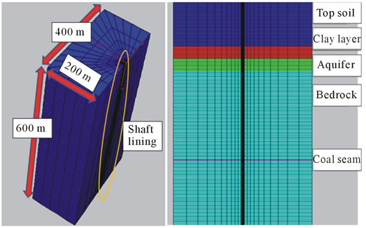
Figure 1. Analysis model.
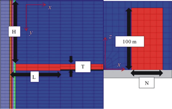
Figure 2. Mining area model.
this mine is 6.5 m and the thickness of the shaft lining is 1.0 m constructed by C28 concrete. The thickness of alluvium is 148.69 m and it contains 3 aquifers. The bottom aquifer is important to the mine and the water level is affected by mining, so in this model, only the bottom aquifer is left for simulation.
According to the engineering geological data and shaft construction data of coal mine, the required mechanical parameters for numerical simulation are shown in Table 1.
As the process of soil deformation and shaft lining stress change is very complex, the following assumptions are made:
• Shaft lining, soil and loss areas are treated as the symmetrical distribution, belong to the space axialsymmetry.
• Concrete shaft lining, the surrounding soil and aquifer are homogeneous, isotropic. No interface between the surrounding soil and shaft lining, that means no sliding in the interface.
Then the boundary conditions are set as follows: a free top surface, two horizontal fixed slides and a vertical fixed the lower surface.
As the coal seam is under the deep bottom aquifer, the different depth, thickness, mining width of coal seam and different distance to the shaft were simulated as the impact factors of the shaft lining and the aquifer (as shown in Table 2).
3. Analysis Results and Discussion
3.1. Failure Initiation Due to Mining Process
The shear strain change is chosen to reveal the impact of the mining process, as the rock compression failure mainly belongs to the shear failure [10]. Figure 3 shows the shear strain distribution around the mining area and the aquifer during mining. The high strain area is in yellow colour and the low strain area is in blue. From this figure, the both ends of the mining area and the aquifer layer have the high strain. In addition, the shear strain in the rock layer between the mining area and the aquifer exceeds 2.0 × 10⁻³. And except the part shown in blue, there is a risk of failure occurs, especially the area between mining area and aquifer. Therefore, the leakage occurs at the impermeability rock layer can be concluded by the fissure developing in the rock which the failure happened during the mining process. According to the above analysis, during the underground mining in 250 m depth, the bedrock under aquifer begins to get loose and then some fissure develops, as a result the aquifer drainage occurs.
Figures 4 and 5 show the distribution of shear strain in different mining depth. The deeper of the mining area, the distance to the aquifer is greater, then the impact on the aquifer is gradually reduced. The impact on the aquifer becomes disappear while mining in 400 m depth, and the shear strain near the mining area tends to become higher. For this reason, if the mining depth is deeper than 400 m, it becomes much more important to consider the

Table 1. Mechanical parameters of soil and shaft lining.
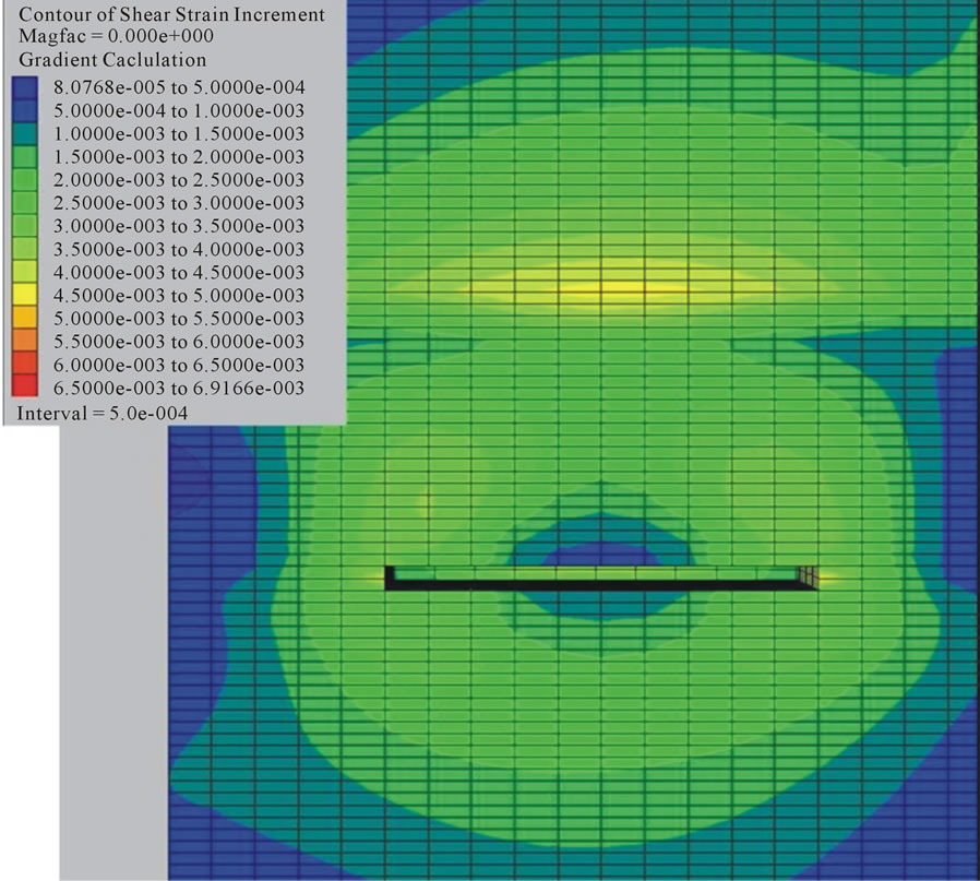
Figure 3. Shear strain distribution during mining (50 m to the shaft and 250 m mining depth, 6 m thickness coal seam).
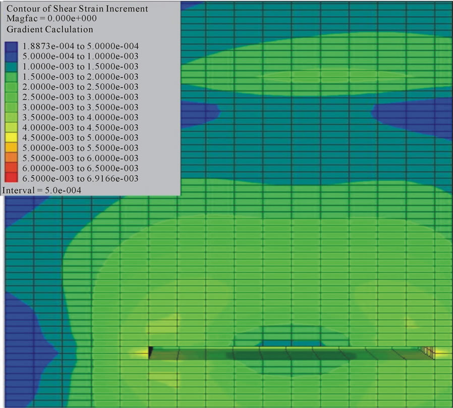
Figure 4. Shear strain distribution during mining (50 m to the shaft and 300 m mining depth, 6 m thickness coal seam).
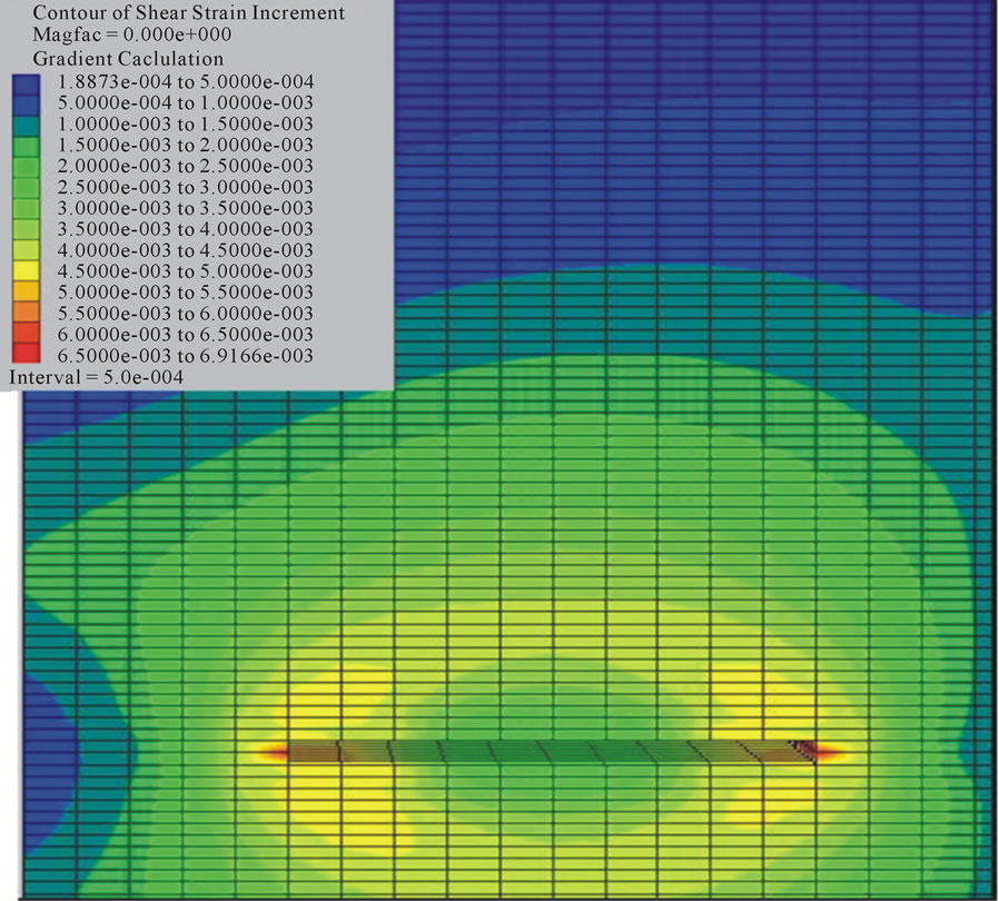
Figure 5. Shear strain distribution during mining (50 m to the shaft and 400 m mining depth, 6 m thickness coal seam).
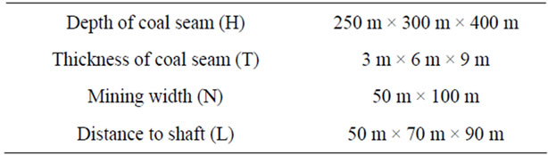
Table 2. Factors for analysis.
safety of the surrounding area compare with the impact on the aquifer.
3.2. Impact Due to Mining Distance to Shaft
The stress in shaft lining is the most concerned issue, so the impact to the shaft lining is revealed by stress change. Figure 6 shows the impact on the surrounding areas and the shaft lining by different distance of mining area to the shaft. The lines in the figure are the values of maximum principal stress in the surrounding area, aquifer and shaft lining. As the distance between mining area and shaft becomes greater, the maximum principal stress in shaft lining becomes smaller, the mining impact on the shaft lining becomes smaller and that can reduce the concentration of the maximum stress.
3.3. Impact Due to Mining Depth
The mining depth also has the impact to the stress in the

Figure 6. Impact due to distance to shaft (250 m mining depth).
shaft lining, though Figure 7 shows the maximum principal stress change due to different mining depths. As the mining area is deeper and the overburden increases, the deformation of surrounding area is greater and the stress concentration in mining area and shaft lining tends to rise as the depth increases. Also the maximum principal stress in the mining area is higher than in the shaft lining. From the above analysis, the risk of shaft lining rupture is smaller than the risk of mining area collapse. So the coal pillar and artificial support need to be remained in
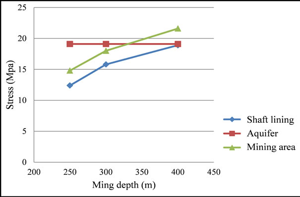
Figure 7. Impact due to mining depth (50 m to shaft).
the mining area considering the collapse risks.
3.4. Impact Due to Mining Width
The change of mining width leads to the deformation of the ground layers; the displacement of the ground layers is used to show the impact. Figures 8 and 9 show the influence of 50 m and 100 m mining width. As the mining width increases, the deformation of surrounding mining area increases which it also gives an impact on the deformation of the shaft lining. As shown in Figure 10, when the mining width is 50 m, the maximum principal stress concentration occurs in the surrounding area, and when the mining width is 100 m, the maximum stress occurs in the shaft lining.
Therefore, due to the deformation of the mining area, there is a significant stress concentration occurs in shaft lining. Particularly, a great stress concentration has occurred around the mining area and the impact range of 50 m mining width and 100 m mining width has a large difference. From above analysis, the mining width has a significant impact on the shaft lining, and the failure in shaft lining is much more severe than in the mining area.
3.5. Impact Due to Coal Seam Thickness
Three thicknesses of coal seam are set as 3 m, 6 m and 9 m for examining the impact. And the stress change in the shaft lining, aquifer and mining area is used to reveal the impact of the coal seam thickness.
Figure 11 shows the maximum principal stress in the mining area, aquifer and shaft lining. From the figure, the stress in aquifer has no obvious change. However, the stress in mining area has a significant increase with the increase of the coal seam thickness. Furthermore, the stress in mining area has outstripped the stress in shaft lining. That means the thickness change of coal seam has
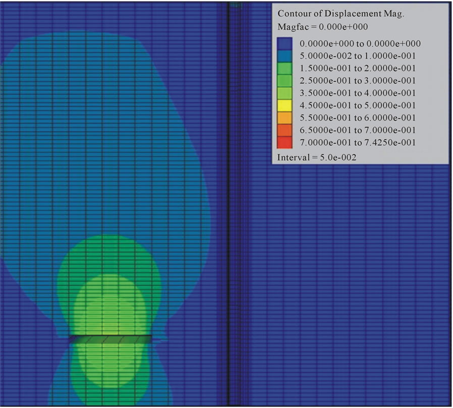
Figure 8. Vertical displacement distributions under 50 m mining width (50 m to the shaft and 400 m mining depth, 6 m thickness coal seam).
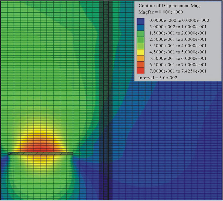
Figure 9. Vertical displacement distributions under 100 m mining width (50 m to the shaft and 400 m mining depth, 6 m thickness coal seam).
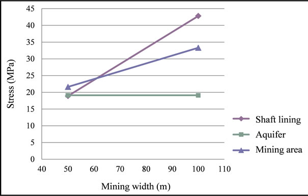
Figure 10. Impact due to mining depth due to mining width (50 m to the shaft and 400 m mining depth, 6 m thickness coal seam).
an impact on the mining area, but not obvious in the shaft lining and aquifer.
4. Conclusions
In this study, the impact of the underground mining on the shaft lining and aquifer is analyzed by numerical simulation. The main aim is to find out the relationship between mechanisms of shaft lining rupture and the underground mining process. The impact factors such as
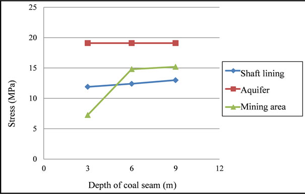
Figure 11. Impact due to coal seam thickness (50 m to shaft and 250 m mining depth).
different depth, thickness, mining width of coal seam and different distance to the shaft are used in the analysis. From a series of numerical simulations, the impact of different factors can be cleared as follows:
• The underground mining process can lead to the initiation of the failure in the soil and rock layers. If the mining location is near some certain range of the aquifer, the aquifer drainage will occur due to the fissure in aquifer connection to fissures in the bedrock. This situation should be avoided in the mining process by changing the mining location or using supporting structure.
• The impact of the mining distance to the shaft lining is obvious, if the mining location is closed to the shaft lining, the greater stress concentration will happen in shaft lining and increase the risk of occurrence of shaft lining rupture.
• When the mining location is near the shaft ling in a certain range, the increase of the mining depth also can increase the risk of occurrence of shaft lining rupture. More seriously, the possibility of mining area collapse is raised due to the increase of mining depth.
• The mining width has a significant impact on the shaft lining, the stress in shaft lining increase fast due to the increase of mining width. Before the increase of the mining width, the support structure should be prepared to protect the mining area in case the stress transfers to shaft lining.
• The thickness change of coal seam has an impact on the mining area, but not obvious in the shaft lining and aquifer.
Therefore, when the mining area under the aquifer nears the shaft lining, there is a significant impact on the shaft lining due to mining process, and the risk of occurrence of shaft lining rupture become higher and need to be concerned.
5. Acknowledgements
Authors are grateful for financial assistance provided by the Global-Centre of Excellence in Novel Carbon Resource Science, Kyushu University.
REFERENCES
- G. Cui and X. Cheng, “Occasions of Damaging Shaft Walls in Xuhuai District,” Coal Science and Technology, Vol. 19, No. 8, 1991, pp. 46-50.
- L. Jing and H. Wang, “The Research about the Fracture Regularity of the Frozen Shaft Wall in Surface Soil,” Journal of Huainan Institute of Technology, Vol. 20, No. 1, 2000, pp. 14-20.
- M. Gu, “Failure of Shaft Caused by Special Geologic Hazards and Corresponding Prevention Measures,” Journal of Engineering Geology, Vol. 8, No. 2, 2000, pp. 197-201.
- W. Yang and H. Fu, “Theoretical Investigation on Vertical Additional Force on Shaft Lining in Special Stratum,” Journal of China University of Mining & Technology, Vol. 9, No. 2, 1999, pp. 129-135.
- G. Zhou and G. Cui, “Numerical Analysis on Interaction between Shaft Wall and Surrounding Strata after Aquifer Grouting,” Journal of China University of Mining & Technology, Vol. 27, No. 2, 1998, pp. 135-139.
- H. Liu, W. Chen and Z. Wang, “Theoretical Analysis of Shaft Lining Damage Mechanism of Yanzhou Mine,” Chinese Journal of Rock Mechanics and Engineering, Vol. 26, Supp. 1, 2007, pp. 2620-2626.
- S. Bi, X. Lou and B. Xu, “On the Mechanism of Coal Mine Shaft Damage Caused by Subsidence in Xuhuai Area, Southeast China,” Communications in Nonlinear Science & Numerical Simulation, Vol. 2, No. 2, 1997, pp. 75-80. doi:10.1016/S1007-5704(97)90043-5
- Yang W., Cui G. and Zhou G., “Fracture Mechanism of Shaft Lining under Special Strata Condition and the Technique Preventing the Shaft From Fracturing (Part One),” Journal of China University of Mining & Technology, Vol. 25, No. 4, 1997, pp. 1-4.
- G. Zhou and X. Cheng, “Study on the Stress Calculation of Shaft Lining Surrounded by Special Strata,” Journal of China University of Mining &Technology, Vol. 24, No. 4, 1995, pp. 24-30.
- M. You and A. Hua, “Fracture of Rock Specimen and Decrement of Bearing Capacity in Uniaxial Compression,” Chinese Journal of Rock Mechanics and Engineering, Vol. 17, No. 3, 1998, pp. 292-296.