Optics and Photonics Journal
Vol.2 No.3A(2012), Article ID:23303,4 pages DOI:10.4236/opj.2012.223034
The Dispersion Characteristics of a One Dimensional Plasma Photonic Crystal Having Inhomogeneous Plasma Density Profiles
Department of Physics, Banaras Hindu University, Varanasi, India
Email: prasad.surendra@gmail.com, viveks@bhu.ac.in, abhay_s@rediffmail.com
Received June 18, 2012; revised July 15, 2012; accepted July 26, 2012
Keywords: Plasma Photonic Crystal; Inhomogeneous Plasma Density; Dispersion Characteristics; Linear Plasma Density Profile; Exponentially Plasma Density Profile
ABSTRACT
The dispersion characteristics of binary 1D-PPCs having inhomogeneous plasma in the unit cell are studied. Using the transfer matrix method the required dispersion relations are obtained. Here the linear and exponential plasma density profiles are considered and compared with the homogeneous plasma having uniform density profile. It is observed that the inhomogeneity in plasma layer highly affect dispersion curves. By comparing the dispersion curves obtained in all considered cases, it is found that the widths of band gaps and phase velocities are always larger for exponential density profile than the linear uniform density profiles in the considered frequency range.
1. Introduction
Photonic crystals (PCs) are periodically structured electromagnetic media in which certain range of electromagnetic (EM) waves are not allowed to propagate through the structure. This range of frequencies is called photonic band gaps (PBGs). The periodicity of the structure and the periodic variation of dielectric constant of different materials are the essential parameters for the formation of these PBGs [1]. These PCs have achieved archival interest worldwide because for its numerous applications such as: Filters, optical switches, waveguides, cavities and design of more efficient layers, etc. [2].
Recently, plasma photonic crystals (PPCs) have attracted the attention of researchers because the properties of these PPCs are externally controllable and it possesses the characteristics of conventional PCs and plasma. The unit cell of PPCs consists of periodic arrangement of plasma and dielectric/air. The dispersion relation of binary one dimensional plasma photonic crystals 1D-PPCs by solving Maxwell equations using a method analogous to the Kronig-Penny’s problem in quantum mechanics is derived by Hojo et al. [3] and discussed the effect of plasma density, thickness of plasma layer and dielectric constant of dielectric media on the dispersion characteristics. Subsequently many research groups analyzed the dispersion and optical properties of 1D-PPCs [3-8]. The dispersion relation of binary 1D-PPCs considering the collision effect in plasma with obliquely incident EM waves is deduced by Guo Bin [6]. Also the dispersion and propagation characteristics of ternary 1D-PPCs have been studied by Prasad et al. [7,8] and they found that the ternary 1D-PPCs provide additional degree of freedom to control the dispersion and propagation characteristics compared to binary 1D-PPCs. But most of the researchers have analyzed the dispersion characteristics, modal propagation characteristics, reflection and transmission coefficients of 1D-PPCs in which a unit cell consists of homogeneous plasma and homogeneous dielectric materials and they obtained that these properties are being controlled by plasma density, thickness of plasma layers, collisions in plasma layer, dielectric constant of dielectric materials and external magnetic fields [9,10]. The PBGs of 1D-PPCs can also be improvise in desire range by considering inhomogeneous dielectric layer in the unit cell of PPCs [11,12].
Similarly, the dispersion characteristics and optical properties of PPCs can also be controlled by considering inhomogeneous plasma in the unit cell. This consideration is more practical also because homogeneous plasma having uniform density is rarely realized in the laboratory plasma [13]. The inhomogeneities in the plasma layer may occur due to spatially dependent plasma density. Therefore, in present communication the propagation of EM waves in 1D-PPCs having inhomogeneous plasma in the unit cell is considered. By using the transfer matrix method (TMM) the dispersion relations of proposed structures are obtained. The dispersion characteristics of PPCs are compared by taking exponential density profile and linear density profile with uniform (constant) density in the plasma layer. The inhomogeneous plasma with linear density profile [14] and exponentially density profile [15] have been chosen because their closeed form solutions are available in terms of special mathematical functions such as Airy and Bessel functions. The paper is organized as follow: In Section 2 formulas for the dispersion relation of the proposed structure is given. The other necessary formulas used in this paper are also presented. Section 3 is devoted to result and discussion. A conclusion is drawn in Section 4.
2. Theoretical Modeling
A plane EM waves with angular frequency ω is assumed to obliquely incident on the 1D-PPCs structure. The unit cells of considered 1D-PPCs have periodic arrangement of inhomogeneous plasma and homogeneous dielectric material. The unit cell is shown in Figure 1. The dielectric material and inhomogeneous plasma are assumed to be non-magnetic. For simplicity, collisions in inhomogeneous plasma are neglected. The plasma density varies either linearly or exponentially in space and is given by n(x). The linear plasma density profile is given as:
 (1a)
(1a)
Similarly, the exponential plasma density profile is given as:
 (1b)
(1b)
where b is the width of plasma layer, p is gradation parameter for controlling variation of density in the plasma layer and ncr is the critical density [14] . The permittivity profile for inhomogeneous plasma and dielectric media is given by:
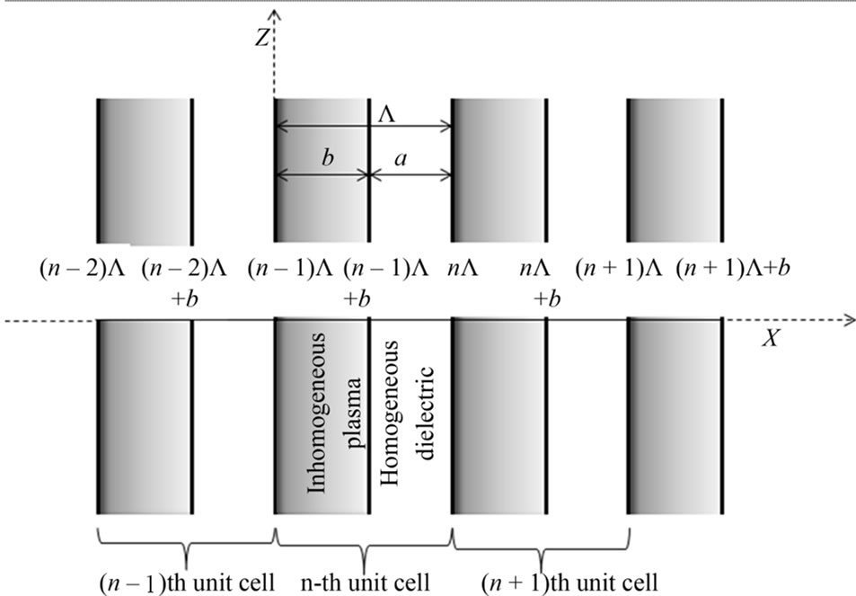
Figure 1. Schematic representation of the unit cell of binary 1D-PPCs having inhomogeneous plasma density layers with homogeneous dielectric layers.
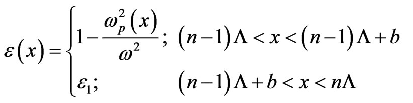 (2a)
(2a)
For linear plasma density profile, the permittivity is written as:
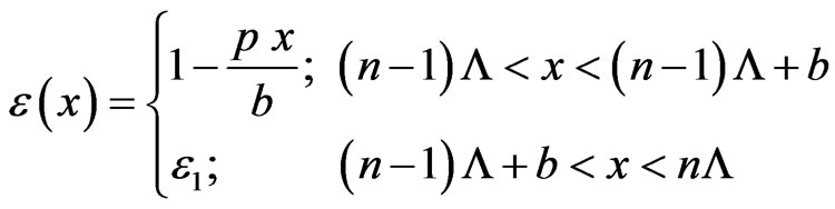 (2b)
(2b)
with condition that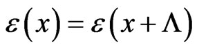 . Here ε1 is the dielectric constant of dielectric layer,
  , a and b are widths of dielectric and plasma layer respectively. The permittivity profile is linearly varying with space along x-direction. The electric field in the case of TE mode is in y-z plane. Along the z-direction there is no change in permittivity, so z-component of wave vector is conserved. The one dimensional wave equation for the spatial part of
 :
:
 (3)
(3)
Typical field solution can be expressed as  and using this in Equation (3) we can write the above equation both regions: inhomogeneous plasma layer and dielectric medium in the nth unit cell as:
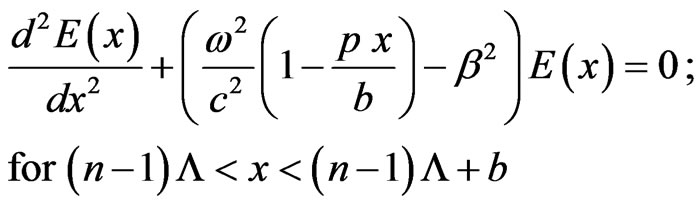 (4)
(4)
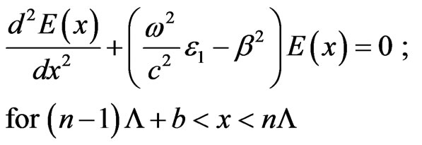 (5)
(5)
where β is the z-component of wave-vector and is given by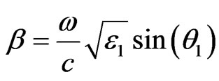 . Using Snell’s law, angle θ1 can be calculated. If θ is the angle of incidence then
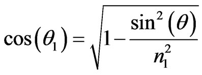 with
with . Here, it is assumed that EM waves incident from vacuum at certain angle θ.
The solutions of above equations for electric fields in the nth unit cell are given by
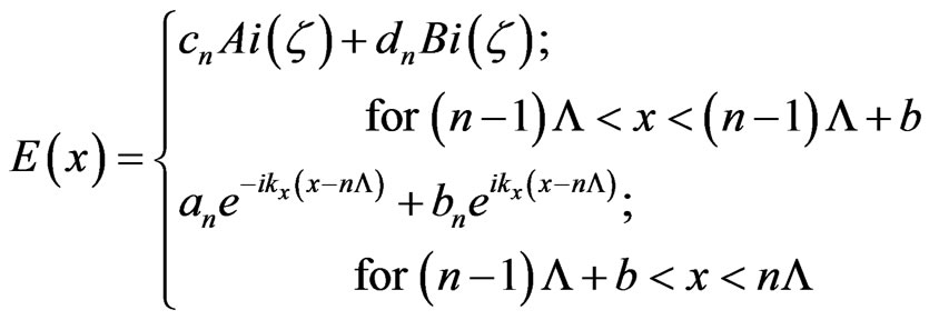 (6)
(6)
where 
and
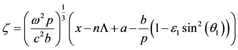 Ai and Bi are Airy functions. Now, using the continuity condition of electric field E(x) and its derivatives at boundaries
  and
and  and TMM, we obtain following matrix relation:
 (7)
(7)
where m11, m12, m21 and m22 are elements of unit translation matrix [16], which relates complex amplitudes of incident and reflected wave in  cell to corresponding amplitudes in nth cell. According to Floquet Theorem, wave propagating in a periodic medium is of form
 , where
  is periodic with period L which is expressed as:
 (8)
(8)
The constant K is known as the Bloch wave number. Here the subscript of k1x is dropped for simplicity in notations and k1x is K. Now the problem at hand is to determine K and  as functions of w and b. In terms of column vector representation and using Equation (6), the periodic condition (8) for Bloch wave is simply given:
 (9)
(9)
It follows from Equations (7) and (8) that the column vector of Bloch wave satisfies the following eigen-value problem
 (10)
(10)
The phase factor eiKΛ is the eigen-value of the unit translation matrix (m11, m12, m21 and m22) and is given by:
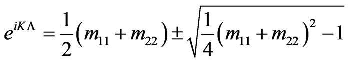 (11)
(11)
So using Equation (11), the dispersion relation for proposed structure can be written as:
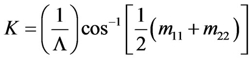 (12)
(12)
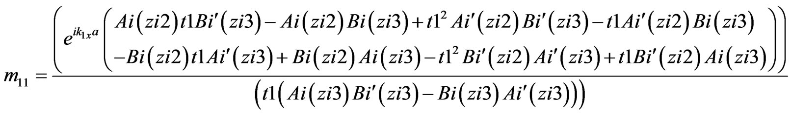
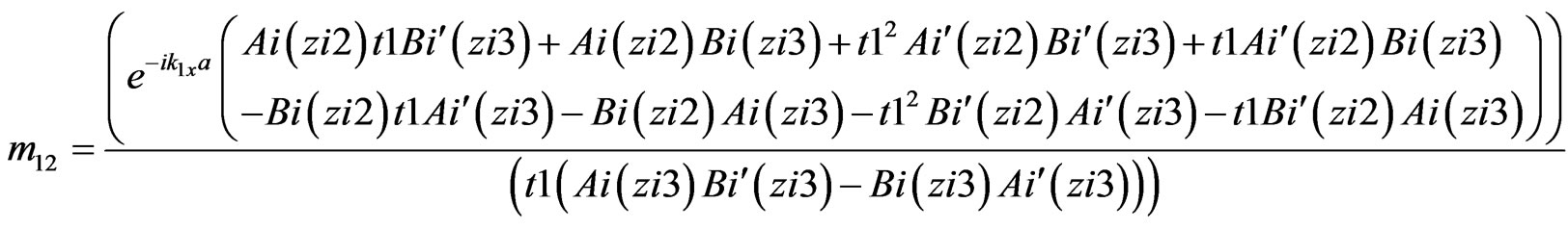
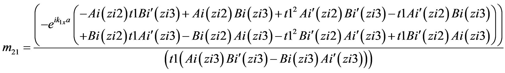
Similarly, we can also find the unit translation elements: m11, m12, m21 and m22 for exponential density profiles. The elements of unit translation elements for exponential density profile and linear density are given in the Appendix 1 and Appendix 2, respectively. In case of uniform (constant) density, the unit translation element can be easily obtained [6].
3. Results and Discussion
The Equation (12) is known as dispersion relation which will give all the information regarding PBGs of the considered (linear plasma density and exponential plasma density) profiles. The unit cell of proposed PPCs structure contains inhomogeneous plasma of width b and homogeneous dielectric of width a. Here the thickness of inhomogeneous plasma b is related with homogeneous dielectric layer width a by the relation . Here d is the ratio of thickness of two layers. The permittivity profile in inhomogeneous plasma layer is
 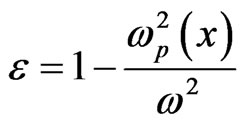 and homogeneous dielectric layer is glass with dielectric constant e1 = 2.25. In the case of homogeneous plasma layer, the plasma frequency ωp is constant and its value is
 . There are five selection parameters; incident angles θ, gradation parameter p, a, d and e1 involved in the numerical calculations.
Figure 2 are plotted to observe the effect of incident angles on the dispersion characteristics of PPCs having inhomogeneous plasma density profiles. These figures show the variation of normalized wave-vector (KL) with normalized frequency  at various angle of incidencewhere
 . For the comparison purpose, the exponential plasma density profile and linear plasma density profile are chosen in such a way that their volume average permittivity is constant at 0.5. It is clear from Figure 2(a) that the lower edge frequency of first band gap
 and second band gap
  are nearly same for exponential density (solid line) and linear density (dash line) profiles at incident angle
 . Also, the width of band gap is large for exponential plasma density profile than the linear plasma density profile. By comparing these results with the case of homogeneous plasma having uniform density profile (dotted line), it is observed that the width of band gap of uniform density profile and linear density profile is approximately equal for first band gap but differ in higher order band gaps. Figure 2 show that as the angle of incidence increases from
  to
to , the lower edge frequencies of first and second band gaps of exponential density profile (solid line) remain intact with linear density profile (dash line) and are shifted towards higher frequency. Such types of behaviors are not observed in the case of uniform density profile (dotted line). This is a remarkable result of present investigation. It is also observed that with increase in angle of incidence, the width of band gaps
 (a)
(a)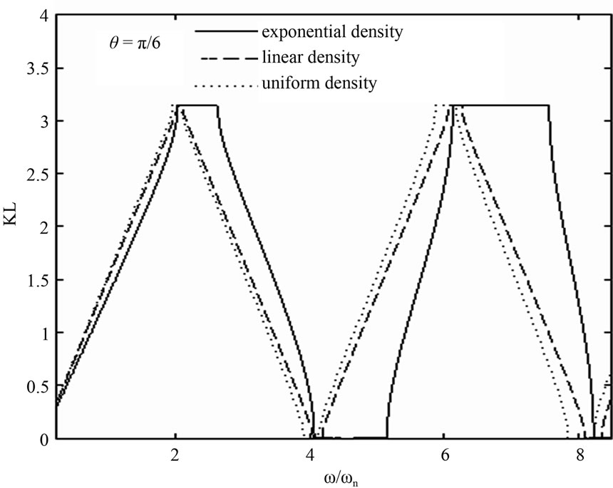 (b)
(b)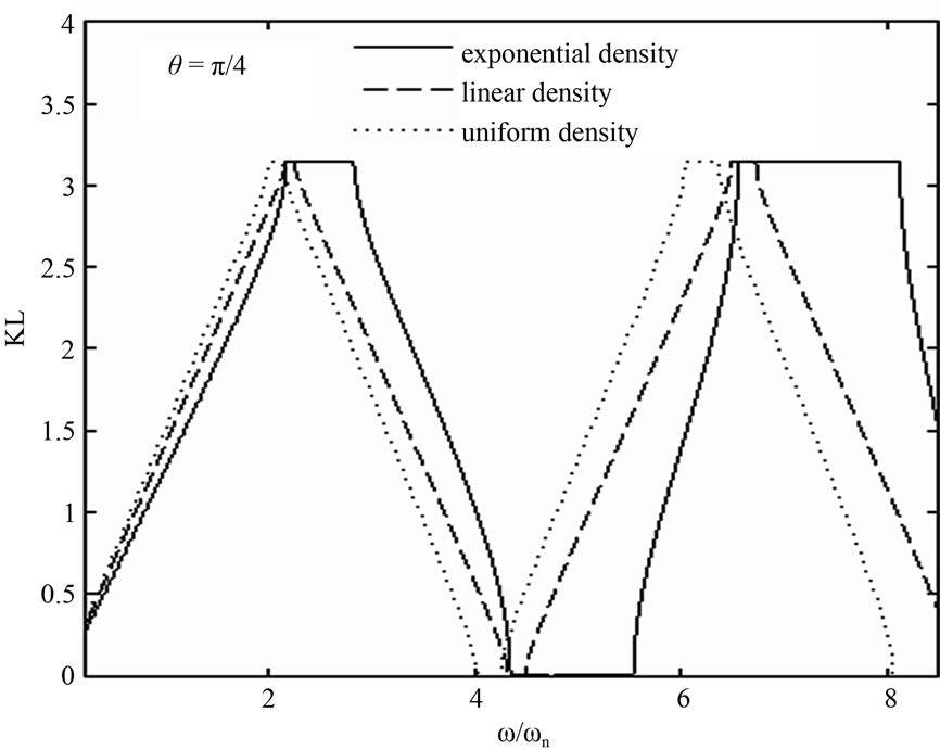 (c)
(c)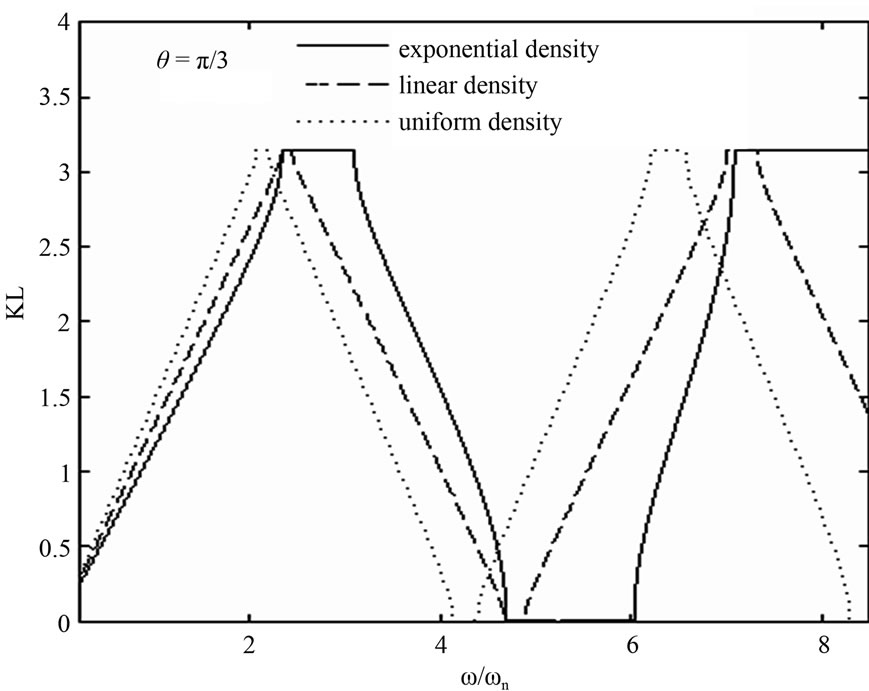 (d)
(d)
Figure 2. The variation of normalized wave-vector (KL) with normalized frequency (w/wn) for a = 5000 µm, d = 0.1, e1 = 2.25 at (a) θ = π/10; (b) θ = π/6; (c) θ = π/4 and (d) θ = π/3.
increases in all considered profiles. It is also clear from Figure 2 that the width of band gaps and phase velocities are always larger for exponential density profile than corresponding band gaps and phase velocities of the linear density profile and uniform density profile in the considered frequency range. The reason is that in the case of exponential density profile, the permittivity contrast changes rapidly than the linear density profile and uniform density, hence produces more Bragg’s reflections.
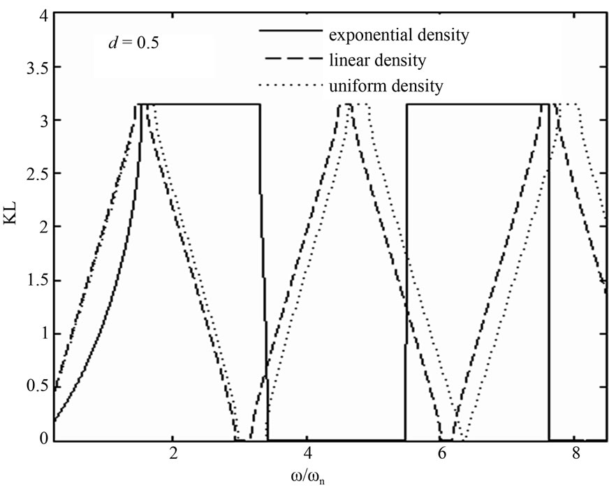
Figure 3 are plotted to analyze the effect of thickness of inhomogeneous plasma layer on the dispersion characteristics. Figure 3(a) shows that the lower edge frequency of first and higher order band gaps for exponential density profile (solid line) are different from linear density profile (dash line) at d = 0.5.
The interesting feature of this graph is that the lower edge frequency, of first band gap, of linear density profile is now intact with uniform density profile (dotted line). As the thickness of plasma layer increases from d = 0.5 to 1.0, as shown in Figures 3(a) and (b), the lower edge frequency of first band gap for linear density profile and uniform density profile remains intact and are shifted towards lower frequency. At d = 2.0 (shown in Figure 3(c)) the lower edge frequency of first band gap become different for all profiles. From the analysis of Figure 3, it is observed that as the thickness of plasma layer changes from d = 0.5 to d = 2.0, number of band gaps get increased. Also, it is found that widths of first and higher order band gaps are different for all three density profiles and larger for exponential density profile.
Figure 4 is plotted to analyze the effect volume average permittivity on the dispersion characteristics for a = 5000 µm, d = 0.1,  , ε1 = 2.25. In this case, the considered volume average permittivity is 0.8394. By comparing Figure 4 from the Figure 2(a) which is plotted at the same parameter with volume average permittivity 0.5. It is observed that as the volume average permittivity increases the widths of band gaps also increase for all profiles and the lower edge frequency of first band gap of all considered profiles remains intact but shifted towards lower frequency.
From this study, it is found that position and width of
 (a)
(a)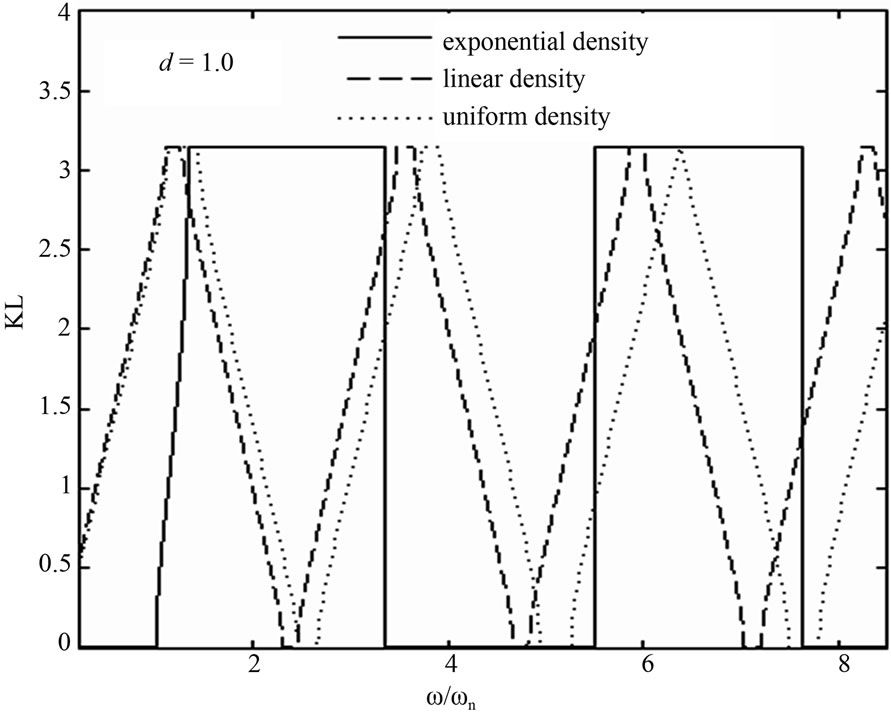 (b)
(b)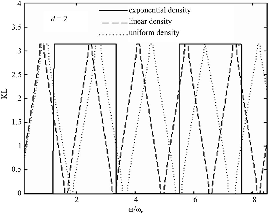 (c)
(c)
Figure 3. The variation of normalized wave-vector (KL) with normalized frequency (w/wn) for a = 5000 µm, θ = π/10, e1 = 2.25 at (a) d = 0.5; (b) d = 1.0 and (c) d = 2.0.
band gaps strongly depend on the density profile and by choosing suitable profile; one can tune the band gaps in desired frequency range.
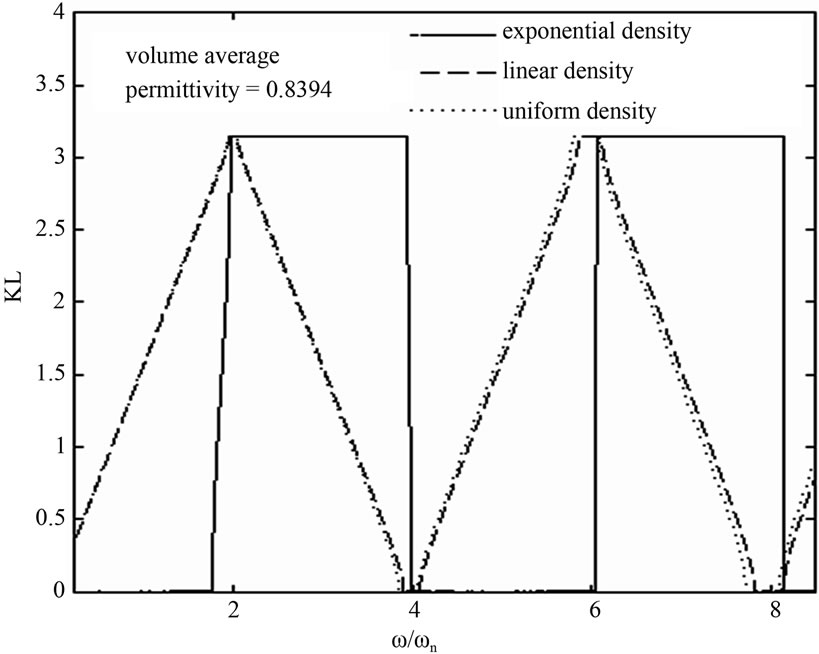
Figure 4. The variation of normalized wave-vector (KL) with normalized frequency (w/wn) for a = 5000 µm, d = 0.1, θ = π/10, e1 = 2.25 at volume average permittivity = 0.8394.
4. Conclusions
The dispersion characteristics of a plasma photonic crystal having inhomogeneous plasma density profile have been studied at the first time in our knowledge. The exponential and linear types of inhomogeneity in the plasma density profile are considered because homogeneous plasma having uniform density is rarely realized in the laboratory plasma. A comparison is also made with 1D-PPCs having homogeneous plasma with uniform density profile. It is observed that, for a constant volume average permittivity, the exponential density profile will always give larger band gaps widths than linear density profile and uniform density profile. With increase in angle of incidence, the widths of band gaps increase and at the same time band gaps are shifted towards higher frequency for all considered profiles. The number of band gaps also increases with increase of the thickness of inhomogeneous/homogeneous plasma layer. This analysis shows that with increase in the volume average permittivity, the widths of band gaps are increased and the lower edge frequency of first band gap remains intact but shifted towards lower frequency for all profiles. The important finding of this study is that the lower edge frequency of first band gap for exponential density profile and linear density profile remains intact and shifted towards higher frequency with increase in incident angle.
Finally, it is concluded that the width and position of band gaps strongly depend on the type of density profile of the plasma layer. Therefore, for correct prediction about the width and position of band gaps, the type of density profile should be ensured in PPCs.
5. Acknowledgements
The authors are grateful to Dr. B. Prasad and Dr. R. D. S. Yadava for their continuous encouragement and supports in many ways.
REFERENCES
- E. Yablonovitch, “Inhibited Spontaneous Emission in SolidState Physics and Electronics,” Physical Review Letters, Vol. 58, No. 20, 1987, pp. 2059-2063. doi:10.1103/PhysRevLett.58.2059
- G. Guida, “An Introduction to Photonic Band Gap (PBG) Materials,” Progress in Electromagnetics Research, Vol. 41, 2003, pp. 1-20. doi:10.2528/PIER02010801
- H. Hojo and A. Mase, “Dispersion Relation of Electromagnetic Waves in one-Dimensional Plasma Photonic,” Journal of Plasma and Fusion Research, Vol. 80, No. 2, 2004, pp. 89-90. doi:10.1585/jspf.80.89
- L. Shiveshwari and P. Mahto, “Photonic Band Gap Effect in One-Dimensional Plasma Dielectric Photonic Crystals,” Solid State Communications, Vol. 138, No. 3, 2006, pp. 160-164. doi:10.1016/j.ssc.2005.11.024
- S. Liu, W. Hong and N. Yuan, “Finite-Difference TimeDomain Analysis of Unmagnetized Plasma Photonic Crystals,” International Journal of Infrared and Millimeter Waves, Vol. 27, No. 3, 2006, pp. 403-423. doi:10.1007/s10762-006-9075-x
- G. Bin, “Photonic Band Gap Structures of Obliquely Incident Electromagnetic Wave Propagation in a One-Dimension Absorptive Plasma Photonic Crystal,” Physics of Plasmas, Vol. 16, No. 4, 2009, Article ID: 043508. doi:10.1063/1.3116642
- S. Prasad, V. Singh and A. K. Singh, “Modal Propagation Characteristics of EM Waves in Ternary One-Dimensional Plasma Photonic Crystals,” Optik, Vol. 121, No. 16, 2010, pp. 1520-1528. doi:10.1016/j.ijleo.2009.02.024
- S. Prasad, V. Singh and A. K. Singh, “A Comparative Study of Dispersion Relation of EM Waves in Ternary One-Dimensional Plasma Photonic Crystals Having Two Different Structures,” Optik, Vol. 122, No. 14, 2011, pp. 1279-1283. doi:10.1016/j.ijleo.2010.08.015
- L. Qi, Z. Yang, F. Lan, X. Gao and Z. Shi, “Properties of Obliquely Incident Electromagnetic Wave in One-Dimensional Magnetized Plasma Photonic Crystals,” Physics of Plasmas, Vol. 17, No. 4, 2010, Article ID: 042501. doi:10.1063/1.3360296
- L. Yang, Y. Xie, P. Yu and G. Wang, “Electromagnetic Bandgap Analysis of 1D Magnetized PPC with Oblique Incidence,” Progress in Electromagnetics Research M, Vol. 12, 2010, pp. 39-50. doi:10.2528/PIERM10012211
- S. Prasad, V. Singh and A. K. Singh, “Modeling of a Filter from One-dimensional Plasma Photonic Crystal Having Exponentially Graded Material in Submillimeter Range,” Journal of Optics Research, Vol. 12, No. 3-4, 2011.
- S. Prasad, V. Singh and A. K. Singh, “Study of Reflection Spectra of One Dimensional Plasma Photonic Crystals Having Exponentially Graded Materials,” Plasma Science and Technology, 2012, in Press.
- D. G. Swanson, “Plasma Waves,” 2nd Edition, IOP Publishing Ltd., Philadelphia, 2003.
- W. L. Kruer, “The Physics of Laser Plasma Interactions,” Addison-Wesley Publishing Company Inc., Boston, 1988.
- V. L. Ginburg, “The Properties of Electromagnetic Waves in Plasmas,” 2nd Edition, Pergamon Press, Oxford, 1964.
- P. Yeh, A. Yariv and C. S. Hong, “Electromagnetic Propagation in Periodic Stratified Media-I. General Theory,” Journal of the Optical Society of America, Vol. 67, No. 4, 1977, pp. 423-438. doi:10.1364/JOSA.67.000423
Appendix: 1
Unit Translation Matrix Elements for 1D-PPCs with Exponential Plasma Density
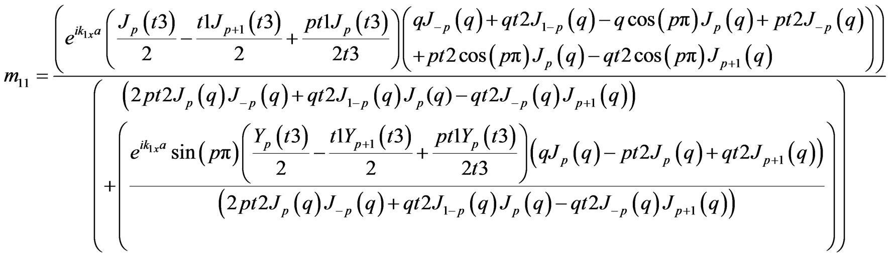
where ;
; ;
;
 ;
; ;
; ;
; 
Appendix: 2
Unit Translation Matrix Elements for 1D-PPCs with Linear Plasma Density

where ;
; ;
;
 ;
;