Optics and Photonics Journal
Vol.2 No.2(2012), Article ID:20401,8 pages DOI:10.4236/opj.2012.22014
Comparative Study of the One Dimensional Dielectric and Metallic Photonic Crystals
1Department of Physics, Faculty of Sciences, Beni-Suef University, Beni-Suef, Egypt
2YJ-STRC, The American University in Cairo, New Cairo, Egypt
3Department of Physics, The American University in Cairo, New Cairo, Egypt
Email: arafaaly@aucegypt.edu
Received February 22, 2012; revised April 2, 2012; accepted April 22, 2012
Keywords: Transmission; Metallic Photonic Crystals; Dielectric Photonic Crystals; Photonic Band Gap
ABSTRACT
The optical transmission properties of two types of photonic crystals have been analyzed by using the transfer matrix method. The first one is the dielectric photonic crystal (DPC), and the second is the metallic photonic crystal (MPC). We found the dielectric and metallic photonic crystals have different transmission spectra. The effect of the most parameters on the transmission spectra of the dielectric and metallic photonic crystals has been studied.
1. Introduction
Photonic crystals (PCs) are macroscopic media which arranged periodically with different refractive indices and their periodicities are in the range of the incident light [1]. In such structures the permittivity is a periodic function in space. In this case, the dielectric permittivity function repeats itself in one dimension (1D) the structure called one dimensional photonic crystal (1D-PC), if it repeats itself in 2D or 3D the structure called 2D or 3D PC. The one dimensional photonic crystal (Figure 1) is a multilayered media. It is worthy to mention that, the propagation of photons in the PCs is similar to the propagation of electrons in the semiconductor crystals, where the effect of the periodic dielectric function on the propagating photon in PCs is much like the effect of the periodic potential function on the propagating electron in semiconductor crystal. Consequently, a photonic band is created in PCs similar to the electronic bad gap in semiconductor crystal [2].
On the other hand, when electromagnetic waves (EM) incident on the PCs Bloch states create in the crystal, if the Bloch wave falls in the so called forbidden bands (photonic band gap) such a wave is evanescent and can’t propagate in the crystal. Thus the light energy is expected to be totally reflected, and the crystal acts as a high reflectance reflector for the incident wave. The photonic band gap of the photonic crystal makes us able to control the light even the spontaneous emission [3]. In this paper, we are going to do comparative study between the 1D-DPCs and -MPCs pointing to the general applications of each kind according to its characteristics.
2. Analysis
2.1. Dielectric Photonic Crystals (DPCs)
In the last decades dielectric photonic crystals have attracted much research interest due to their various applications for example, optical filters, waveguides, and optical fibres [4-7]. In this section, we restrict our communications on the characteristics of the 1D-DPC showing its various applications. The reflection of the EM waves through DPCs exhibit resonance reflection very much like the diffraction of x-rays by crystal lattice planes, therefore it’s called Bragg reflector.
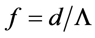
We have designed 1D-DPC composed of a low index material (Cryolite = 1.34) and a high index material (Silicon = 3.4) stacked alternatively on a glass substrate. The number of periods, lattice constant, effective refractive index, and the filling factors of the low and the high index materials are taken to be 10, 250, 2.389, 0.6, and 0.4 nm, respectively. The filling factor (f) of a material in a 1D-PC can be given by [8];
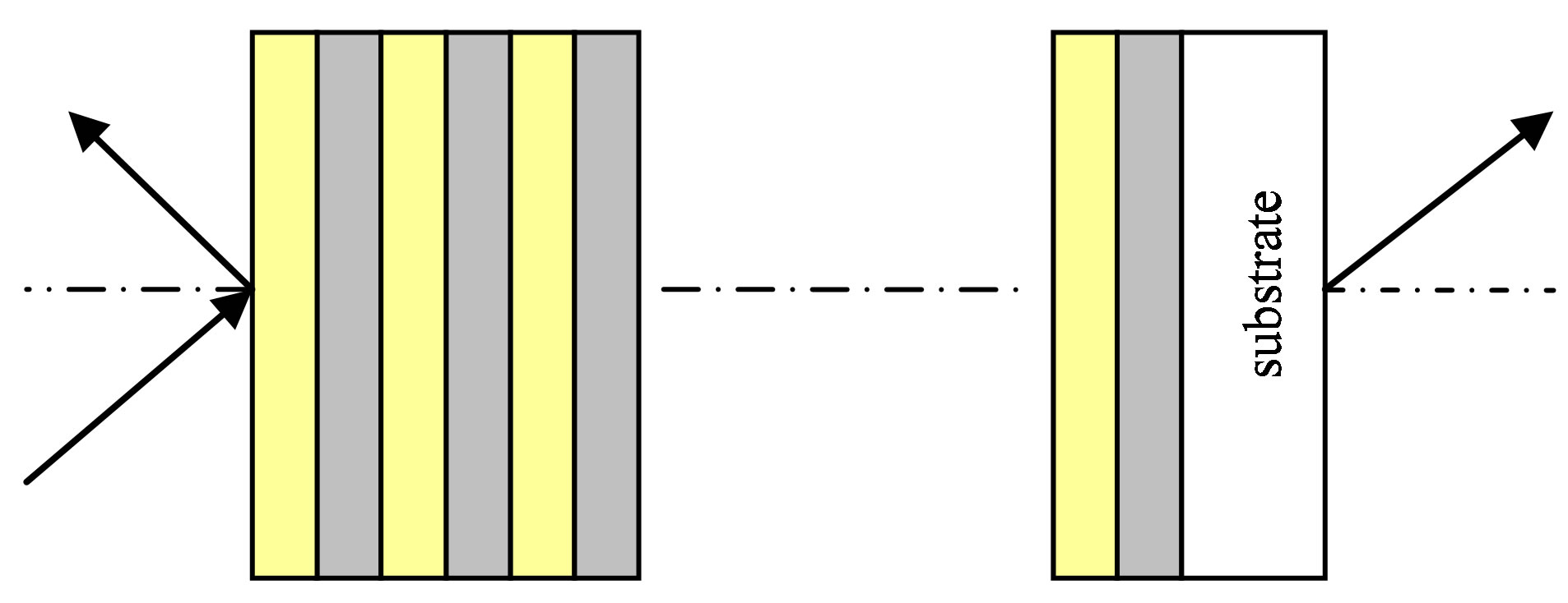
Figure 1. Schematic diagram shows a one dimensional photonic crystal.
 (1)
(1)
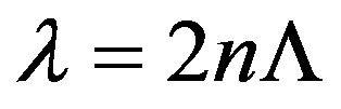
where d and  are the material layer thickness in the unit cell of the PC and the lattice constant (spatially periodic constant), respectively. The transmission spectra of the DPC are displayed in Figure 2. The figure shows that the DPC presents a transmission band for the low frequencies (long wavelengths), and the first band gap is associated with the Bragg condition [2];
 (2)
(2)
where  is the centre wavelength of the first band gap,
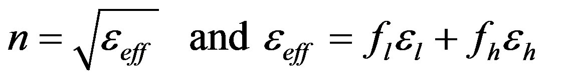
  is the lattice constant, and n is the effective refractive index. The effective refractive index can be given by [2];
 (3)
(3)
The term  represents the filling factor of the low index material multiplied by its permittivity, and the term
  represents the filling factor of the high index material multiplied by its permittivity. The centre wavelength of the first stop band determined by Bragg condition is approximately equal to 1194 nm which is consistent with the value deduced from the transfer matrix method that shown in Figure 2. The photonic band gap of the DPC can be tuneable by varying n or
 , and the band gap can be shift to longer (shorter) wavelengths with increasing (decreasing) the lattice constant or the effective index as Bragg condition predict.
It’s known that, in a specified frequency range the band gap width depends on the difference in the refractive indices of the two constituent materials ( ). So to show effect of
  we have designed DPC from Cryolite/Silicon dioxide (
 ). The transmission spectra are displayed in Figure 3, it is obvious that, when the number of periods is equal to ten,
  of Cryolite/Silicon dioxide is small not enough to open deep gap, but when the number of periods become equal to fifty, a narrow deep gap can be open. We have observed that the number of periods doesn’t effect on the position or the width of the band gap. But increasing number of periods enhances the reflectivity of the bad gap and makes the band gap edges steeper.
In Figure 3, the number of the resonance transmission peaks (RTPs) for the PC of fifty periods is larger than number of RTPs for the PC of ten periods. We have noticed that, the RTPs of the DPC is directly proportional to the number of periods, and the RTPs have become closer to each other and sharper as the wavelength decreases and vice versa.
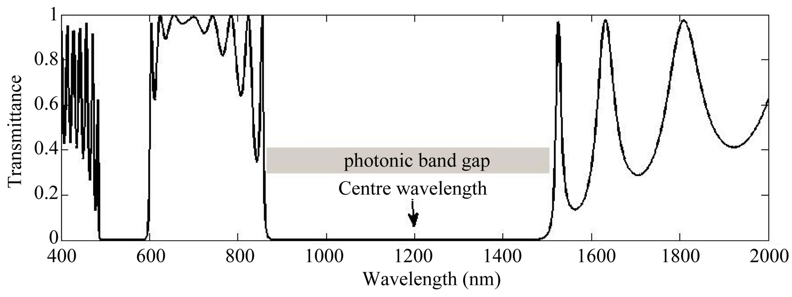
Figure 2. Calculated transmission spectra of a dielectric photonic crystal with n1 = 1.34, n2 = 3.4, d1 = 150 nm, d2 = 100 nm, number of periods = 10, and θ = 0˚.

Figure 3. Calculated transmission spectra of a dielectric PC with n1 = 1.34, n2 = 1.46, d1 = 150 nm, d2 = 100 nm, period = 10, and θ = 0˚.
On the other hand, in order to study the filling factor effect, we have designed two DPCs both composed of Cryolite/Silicon but it is differ in the filling factors of the two constituent materials. The transmission spectra of the two PCs are shown in Figure 4 by increasing the filling factor of the high index material (HIMF) red shift of the band gap occurs, this due to the increase of the effective refractive index of the dielectric stack. It is observed that, the band gap width slightly decreases with increasing the HIMF.
The incidence angle effect on the transmittance of the DPC for Sand P-polarized waves is displayed in the Figures 5 and 6, respectively. When the incidence angle of the electromagnetic waves increase blue shift of the band gaps of the Sand P-polarized waves occur. The band gap of the P-polarized wave shrinks due to Brewster effect at the interface between low and high index layers [9]. But the band gap of the S-polarized wave increases slightly. The forbidden gaps for the two polarizations not coincide due to the loss of the degeneracy. From the Figures 5 and 6, we have observed that, the P-Polarized wave more sensitive to the change of angle than S-polarized wave. 1D-DPCs structure has many applications such as filters [10], omnidirectional reflectors [11-19], polarisers [20-25], antireflection coatings, distributed Bragg reflectors for vertical-Cavity surface emitting lasers (VCSEL), and wavelength division multiplexers/demultiplexers on the basis of fibre Bragg
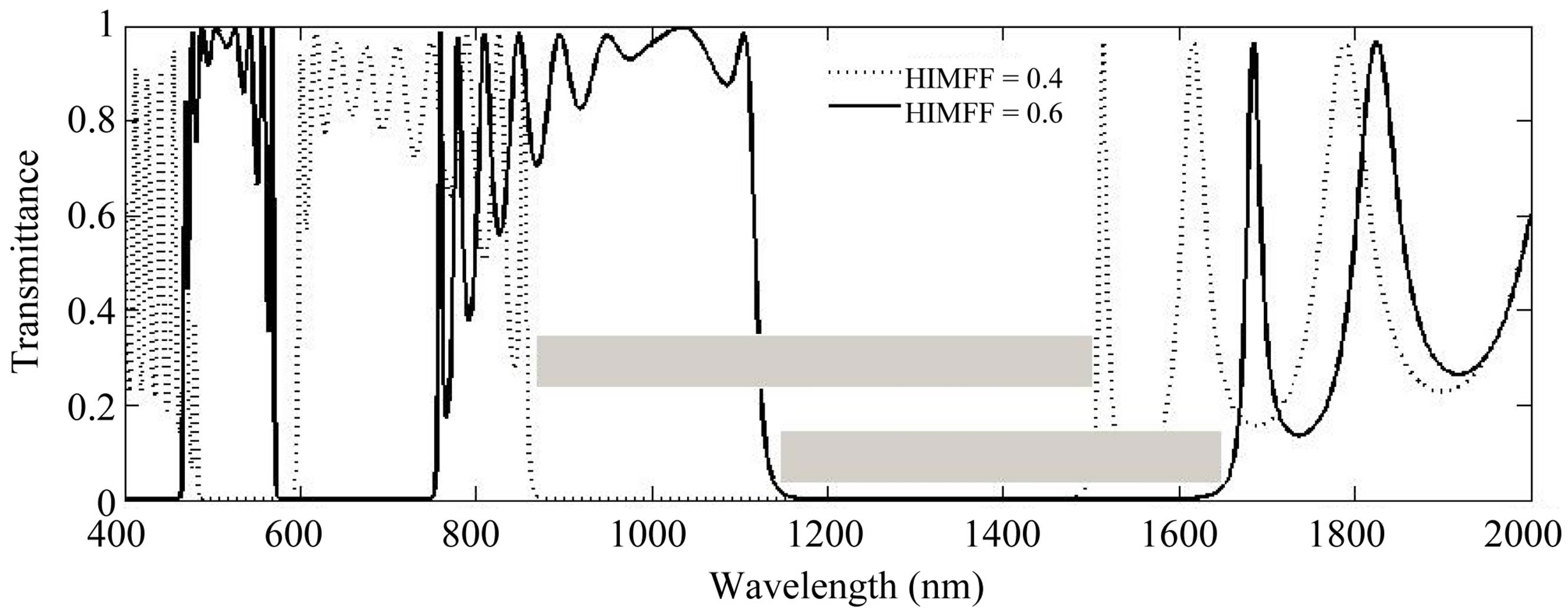
Figure 4. Calculated transmission spectra of two DPCs with n1 = 1.34, n2 =3.4, Λ = 250 nm, θ = 0˚ and different only in the filling factors of the constituent materials.

Figure 5. Calculated transmission spectra of DPC for S-polarized wave at different incident angles; the DPC with n1 = 1.34, n2 = 3.3, d1 = 150 nm, d2 = 100 nm, and number of periods = 10.

Figure 6. Calculated transmission spectra of DPC for P-polarized wave at different incident angles; the DPC with n1 = 1.34, n2 = 3.3, d1 = 150 nm, d2 = 100 nm, and number of periods = 10.
grating (FBG) [3].
2.2. Metallic Photonic Crystals (MPCs)
We have shown in the previous section that, in order to achieve photonic band gap, the system must has high contrast in the refractive index with negligible the absorption of light. These conditions have restricted the set of dielectrics that exhibit a photonic band gap. One suggestion is to use metals which have large value of dielectric permittivity rather than dielectrics. Accordingly a fewer numbers of periods would be enough to achieve photonic band gap [26,27]. We have designed 1D-MPC composed of Cryolite/Silver with 10 periods, lattice constant = 210 nm, and the filling factors of Sillver and Cryolite are 0.0476, and 0.9634, respectively. The dispersion has been taken into account by using Drude model and then we can alculate the refractive index of metals. The transmission spectra of the MPC are displayed in Figure 7. As shown in the figure, the MPC present like the DPC alternation of transmission bands and band gaps with the same progressive decrease of the transmission contrast. However for low frequency region starting from zero frequency of the spectrum, MPC exhibit plasmonic band gap. This plasmonic gap extends from 309.3 THz (970 nm) to zero frequency. This band gap not originated from the structure but from the bulk silver properties. In addition to the plasmonic band gap, the MPC exhibits structural band gap extends from 420 to 570 nm. The structural band gap follows the first transmission band that extends from 570 to 970 nm. The Plasmonic band gap is followed by a first transmission band whose centre wavelength corresponds to Bragg condition. The situation here turns out to be reversed compared to the case of the DPC, where the same exact relation corresponds to the first band gap. The value of the centre wavelength of the first transmission band determined from Bragg condition (750 nm) nearly consistent with the value deduced from the transfer matrix method shown in Figure 7. The first transmission band or the band gaps of the MPC can be tuned by varying n or  as in the DPC.
Figure 8 shows the transmission spectra of the previous designed MPC at the number of periods equal to five periods. By decreasing number of periods, no change in

Figure 7. Calculate transmission spectra of MPC composed of Cryolite/Silver with d1 = 200 nm, d2 = 10 nm, number of periods = 10, and θ = 0˚.

Figure 8. Calculated transmission spectra of MPC composed of Cryolite/Silver with d1 = 200 nm, d2 = 10 nm, θ = 0˚, and periods = 5.
the width of both structural and plasmonic gaps has been noticed, also there is no shift in the transmission spectra has been recorded. But the resonance transmission peaks became less (four), this due to the MPC behaves as ensemble of Fabry-Periot cavities coupled to one another along the propagation direction. So the MPC that composed of ten (five) periods can be regarded as nine (four) Fabry-Periot cavities.
The effect of the filling factor of the dielectric and metal on the transmittance of the MPC is displayed in Figure 9, the figure shows, when the metal filling factor (M.F) is doubled to be 0.096 keeping the lattice constant without change, the low energy edge of the first transmission band move to shorter wavelength without moving the high energy edge causing shrinking the first transmission band width and increasing the plasmonic band gap width. Moreover, the width of the structural band gap increases and the transmittance of the Ag-PC decreases. This behaviour of the MPC can be understood if we regarded the MPC as composite structure which can be described by the effective plasma frequency. The effective plasma frequency proportional to the metallic plasma frequency times the square root of the metal filling factor [28]. So with increasing the metal filling factor the effective plasma frequency increases and the transparent region (transmission band) shift to shorter wavelength. The incidence angle effect on the transmission spectra of the MPC for  and
and  polarized is displayed in the Figures 10, and 11, respectively. For
  and
and  polarized waves, an increase in the incidence angle cause a shift in the structural band gaps and the first transmission band to shorter wavelengths. However,
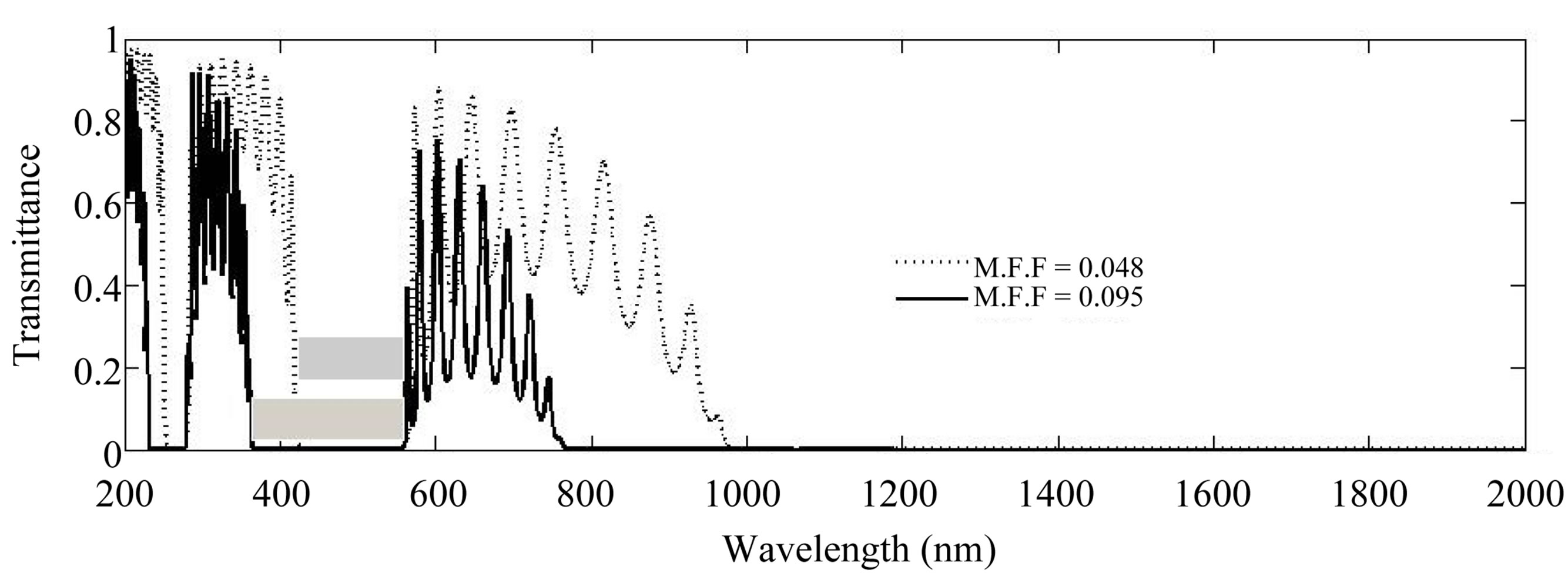
Figure 9. Calculated transmission spectra of two MPCs composed of Cryolite/Silver with periods = 10, θ = 0˚, Λ = 210 nm and different in the Silver filling factor.
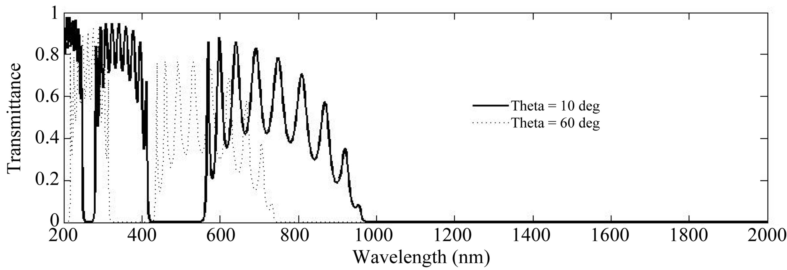
Figure 10. Calculated transmission spectra of MPC of TE waves, where the MPC composed of Cryolite/Silver with d1 = 200 nm, d2 = 10 nm, and periods = 10.

Figure 11. Calculated transmission spectra of MPC of TM waves, where the MPC composed of Cryolite/Silver with d1 = 200 nm, d2 = 10 nm, and periods = 10.
the S-polarized wave has shown blue shift larger than the P-polarized wave. In addition, the low energy edge of the first transmission band for S-polarized wave shifts from 970 to 770 nm nearly 200 nm with the angle change from 10˚ to 60˚. But for P-polarized wave the shift is nearly 50 nm. This behaviour can be understood if we regarded the MPC as a system of several Fabry-Perot cavities coupled. Each metal/dielectric/metal structure in the MPC acts as a Fabry-Perot Cavity and the finite thickness of metal layers makes the cavity modes overlaps. Away from the normal incidence, Fabry-Perot modes satisfy the condition [29];
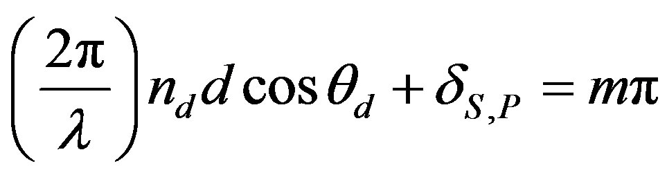 , for m = 1, 2, 3,…(4)
where  is the angle of propagation inside a dielectric layer, and
  is the induced phase shift by the reflection at the dielectric metallic interface for Sand P-polarized waves and given by [29];
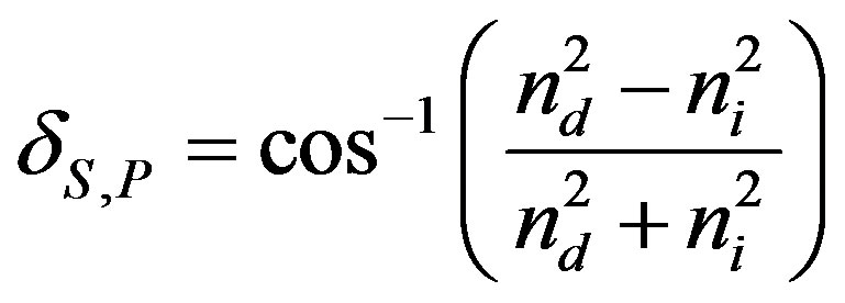 (5)
(5)
where  is the imaginary part of the metal refractive index. The induced phase shift of the Sand P-polarized waves is different, the Fabry-Perot modes for
  and P-polarized waves occur at different frequencies. Away from the normal incidence, the refractive index of the metal layers can be regarded as
  and
and
 for Sand P-polarized waves, respectively. So the effective refractive index for the S-polarized waves is smaller than that for P-polarized waves. According to Equation (5),
  is smaller than
 , and according to Equation (4), the wavelength of the FabryPerot modes for S-polarized wave is smaller than that for P-polarized wave. Therefore, the transmission band in MPCs shifts more toward the shorter wavelength region for S-polarized wave than for P-polarized wave with increasing the angle of incidence.
In order to study the effect of the Plasmon frequency and the damping coefficient of metals on the transmittance of the MPC (Figures 12 and 13), we have designed MPCs composed of different metals (silver, gold, and Aluminium). The magnitudes of Plasmon frequencies and damping coefficients are 2175/4.35 THz (Ag), 2175/6.5 THz (Au), and 3750/19.4 THz (Al). In Figure 12, the transmission spectra of the Cryolite/Agand Cryolite/Au-PCs are displayed. The resonance transmission peaks of the AU-PC occurs at the same wavelengths of the Ag-PC. The plasmonic and the structure band gaps coincide, and have the same width, this due to Ag and Au have the same Plasmon frequency. We can see in Figure 12, Ag-PC has higher resonance transmission peaks than Au-PC, this due to Ag has lower damping coefficient. In Figure 13, the transmittance of the Al-PC is compared to the Ag-PC. The transmittance of the Al-PC is very small compared to the Agor Au-PC
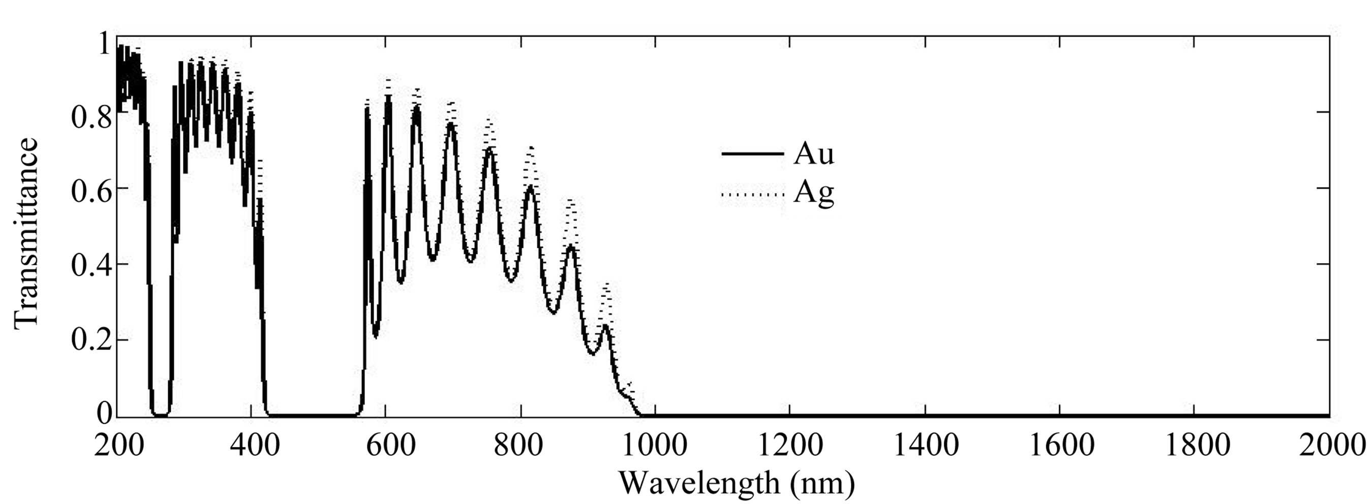
Figure 12. Calculated transmission spectra of Cryolite/Silver and Cryolite/Gold PCs with d1 = 200 nm, d2 = 10 nm, periods = 10, and θ = 0˚.
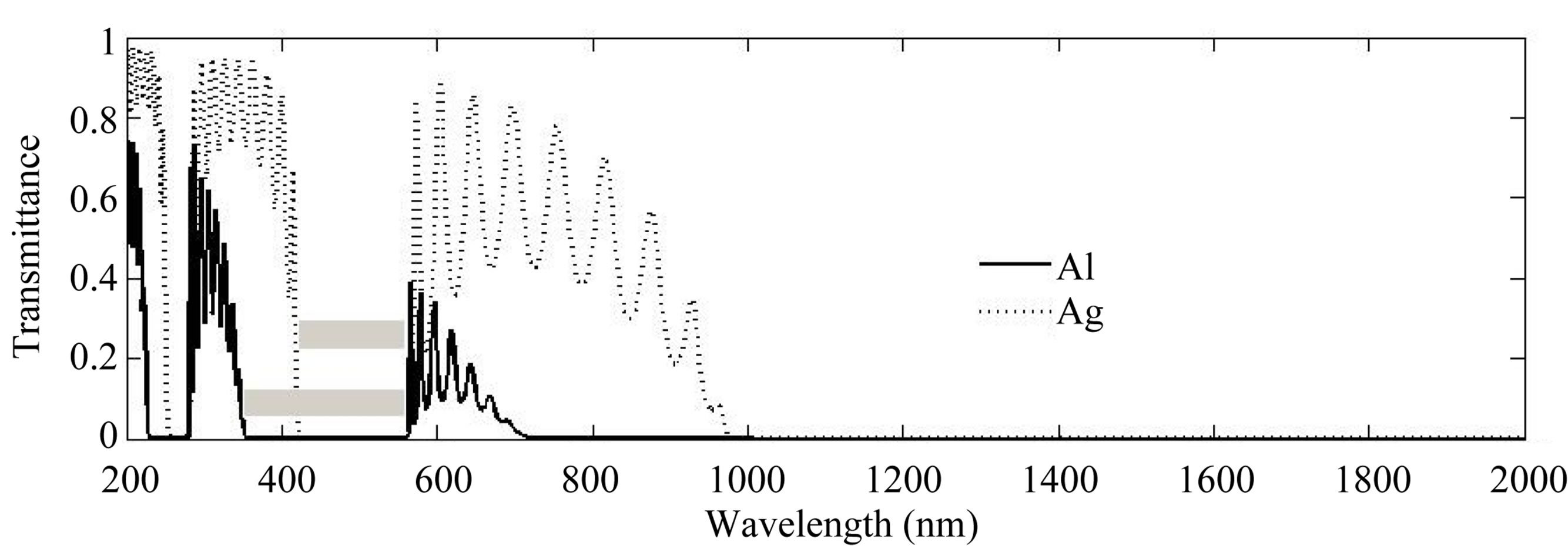
Figure 13. Calculated transmission spectra of Cryolite/Silver and Cryolite/Aluminium PCs with d1 = 200 nm, d2 =10 nm, periods = 10, and θ = 0˚.
this due to the Al has very large damping coefficient. The resonance transmission peaks of the Al-PC occur at shorter wavelengths this because Al has larger value of Plasmon frequency. Figure 13 shows the Al-PC has wider structural and plasmonic band gaps.
The 1D-MPCs can work as mirrors better than the DPCs because it needs fewer numbers of periods to give high reflectance gap. Plasmonic gap of the MPC block the longest wavelengths (microwaves and radiofrequency) and this candidate it to work as radiofrequency shield, microwave ovens doors. It also can work as UV protective.
3. Conclusion
We have designed one dimensional-dielectric and -metallic Photonic crystals showing the difference in the transmission spectra of both. The MPC has both structural and bulk metal band gaps, but the DPC has only Structural band gaps that produce from EM waves interferences. The spectra of dielectric photonic crystal begins with transmission band at lower frequencies, on contrary to the metallic photonic crystal that begins with stop band. The first band gap of the DPC and the first transmission band of the MPC occur at Bragg condition. The resonance transmission peaks of the MPC and the DPC are comparable to the number of periods. In the DPC the P-Polarized waves is more sensitive to the incident angle than the S-Polarized waves, but in the MPC the matter is turned out to be reversed. MPCs of larger damping coefficient metal have lower transmittance, and MPCs of larger Plasmon frequency metal have resonance transmission peaks at shorter wavelengths. Increase the metal filling factor of the MPC do as the Plasmon frequency of the metal increase.
REFERENCES
- A. H. Aly, “Metallic and Superconducting Photonic Crystal,” Journal of Superconductivity and Novel Magnetism, Vol. 21, No. 7, 2008, pp. 421-425.
- J.-M. Lourtioz, H. Benisty, V. Berger, J.-M. Gerard, D. Maystre and A. Tchelnokov, “Photonic Crystals: Towards Nanoscale Photonic Devices,” 2nd Edition, Springer- Verlag Berlin Heidelberg, New York, 2008.
- J. D. Joannopoulos., S. G. Johnson, J. N. Winn and R. D. Meade, “Photonic Crystals: Molding the Flow of Light,” 2nd Edition, Princeton University Press, Princeton, 2008.
- M. Scalora, M. J. Bloemer, A. S. Pethel, J. P. Dowling, C. M. Bowden and A. S. Manka, “Transparent, Metallo-Dielectric, One-Dimensional, Photonic Band-Gap Structures,” Journal of Applied Physics , Vol. 83, No. 5, 1998, p. 2377.
- Q.-H. Gong and X.-Y. Hu, “Ultrafast Photonic Crystal Optical Switching,” Frontiers of Physics in China, Vol. 1, No. 2, 2006, pp. 171-177.
- Z. Jaksic, M. Maksimovie and M. Sarajlic, “Silver-Silica Transparent Metal Structures as Bandpass Filters for the Ultraviolet Range,” Journal of Optics A: Pure and Applied Optics, Vol. 7, No.1, 2005, pp. 51-55
- S. K. Awasthi and S. P. Ojha, “Design of a Tunable Optical Filter by Using a One-Dimensional Ternary Photonic Band Gap Material,” Progress in Electromagnetics Research M, Vol. 4, 2008, pp. 117-132. doi:10.2528/PIERM08061302
- S. K. Awasthi and S. P. Ojha, “Wide-Angle Broadband Plate Polarizer with 1D Photonic Crystal,” Progress in Electromagnetics Research, Vol. 88, 2008, pp. 321-335.
- D. N. Chigrin, A. V. Lavrinenko, D. A. Yarotsky and S. V. Gaponenko, “Observation of Total Omnidirection Reflection from a One-Dimensional-Dielectric Lattice,” Applied Physics A, Vol. 68, No. 1, 1999, pp. 25-28. doi:10.1007/s003390050849
- P. K. Choudhury, P. Khastgir, S. P. Ojha, D. K. Mahapatra and O. N. Singh, “Design of an Optical Filter as a Monochromatic Selector from Atomic Emission,” Journal of the Optical Society of America A, Vol. 9, No. 6, 1992, pp. 1007-1010. doi:10.1364/JOSAA.9.001007
- J. N. Winn, S. Fan, C. Chen, J. Michel, J. D. Joannopoulos and E. L .Thomas, “A Dielectric Omnidirectional Reflector,” Science, Vol. 282, No. 5394, 1998, pp. 1679-1682.
- O. Zandi, Z. Atlasbaf and K. Fabororaghi, “Flat Multilayer Dielectric Reflector Antennas,” Progress in Electromagnetics Research, Vol. 72, 2007, pp. 1-19. doi:10.2528/PIER07022604
- M. Aissaoui, J. Zaghdoudi, M. Kanzari and B. Rezig, “Optical Properties of the Quasi-Periodic One-Dimensional Generalized Multilayer Fibnoacci Structures,” Progress in Electromagnetics Research, Vol. 59, 2006, pp. 69-83. doi:10.2528/PIER05091701
- T. Maka, D. N. Chaigrin, S. G. Romanov and C. M. S. Torres, “Three Dimensional Photonic Crystals in the Visible Regime,” Progress in Electromagnetics Research, Vol. 41, 2003, pp. 307-335. doi:10.2528/PIER0201089e
- C.-J. Wu, “Transmission and Reflection in a Period Superconductor/Dielectric Film Multilayer Structure,” Journal of Electromagnetic Waves and Applications, Vol. 19, No. 15, 2005, pp. 1991-1996. doi:10.1163/156939305775570468
- L.-P. Zhao, X. Zhao, B. Wu, T. Su, W. Xue and C.-H. Liang, “Novel Design of Dual—Mode Bandpass Filter Using Rectangle Structure,” Progress in Electromagnetics Research B, Vol. 3, 2008, pp. 131-141. doi:10.2528/PIERB07121003
- J. A. M. Rojas, J. Alpuente, J. Pineiro and R. SanchezMontero, “Regorous Full Vertical Analysis of Electromagnetic Wave Propagation in 1D,” Progress in Electromagnetics Research, Vol. 63, 2006, pp. 89-105. doi:10.2528/PIER06042501
- Q.-R. Zheng, Y.-Q. Fu and N.-C. Yuan, “Characteristics of Planar PBG Structures with Cover Layer,” Journal of Electromagnetic Waves and Applications, Vol. 120, No, 11, 2006, pp. 1439-1453. doi:10.1163/156939306779274264
- M. Deopua, C. K. Ullal, B. Temelkuran and Y. Fink, “Dielectric Omnidirectional-Visible Reflector,” Optics Letters, Vol. 26, No. 15, 2001, pp. 1197-1199.
- M. Thomsen and Z. L. Wu, “Polarizing and Reflective Coatings Based on Half-Wave Layer Pairs,” Applied Optics, Vol. 36, No. 1, 1997, pp. 307-313. doi:10.1364/AO.36.000307
- J. C. Monga, “Multilayer Thin-Film Polarisers with Reduced Electric-Field Intensity,” Journal of Modern Optics, Vol. 36, No. 6, 1989, pp. 769-784. doi:10.1080/09500348914550841
- S. M. MacNeille, “Beam Splitter,” US Patent No. 2403731, 1946.
- J. Mouchart, J. Begel and E. Duda, “Modified MacNeille Cube Polarizer for a Wide Angular Field,” Applied Optics, Vol. 28, No. 14, 1989, pp. 2847-2853. doi:10.1364/AO.28.002847
- L. Li and J. A. Dobrowolski, “Visible Broadband, Wide- Angle, Thin-Film Multilayer Polarizing Beam Splitter,” Applied Optics, Vol. 35, No. 13, 1996, pp. 2221-2225. doi:10.1364/AO.35.002221
- L. Li, and J. A. Dobrowolski, “Hig-Performance ThinFilm Polarizing Beam Splitter Operating at Angles Greater than the Critical Angle,” Applied Optics, Vol. 39, No. 16, 2000, pp. 2754-2771 doi:10.1364/AO.39.002754
- A. H. Aly, S.-W. Ryu, H.-T. Hsu and C.-J. Wu, “THz Transmittance in One-Dimenssional Superconducting Nanomaterial-Dielectric Superlattice,” Materials Chemistry Physics, Vol. 113, No. 16, 2009, pp. 382-384.
- M. M. Sigalas, C. T. Chan, K. M. Ho and C. M. Soukoulis, “Mettalic Photonic Band Gap Materials,” Physical Review B, Vol. 52, No. 16, 1995, pp. 11744-11751.
- J. Manzanares-Martinez, “Analytical Expression for the Effective Plasma Frequency in One Dimentional Metallic-Dielectric Photonic Crystal,” Progress in Electromagnetic Research M, Vol. 13, 2010, pp. 189-202.
- Y.-K. Choi, Y.-K. Ha, J.-E. Kim, H. Y. Park and K. Kim, “Antireflection Film in One-Dimensional Metallo-Dielectric Photonic Crystals,” Optics Communications, Vol. 230, No. 4-6, 2004, pp. 239-243.